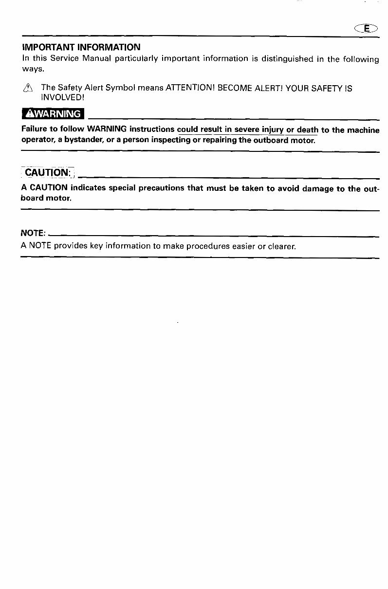
IMPORTANT INFORMATION In this ServiceManual particularly important information isdistinguished inthe following ways. The Safety Alert Symbol means ATTENTION! BECOME ALERT! YOUR SAFETY IS INVOLVED! Ir!¥AV_,_ -"t Lq IIL_ [4 Failure to follow WARNING instructions could result in severe injury or death to the machine operator, a bystander, or a person inspecting or repairing the outboard motor. CAUT!0N: i A CAUTION indicates special precautions that must be taken to avoid damage to the out- board motor. NOTE: A NOTE provides key information to make procedures easier or clearer.
CED INFORMATIONS IMPORTANTES Les informations plus particuli_rement importantes pr6sent6es dans ce manuel de service sont mises en 6vidence de la fagon sui- vante. _5 Ce symbole signale un danger: ATTENTION DANGER ! SOYEZ ATTENTIF ! VOTRE SECURITE EST EN JEU ! Le respect des eonsignes AVERTISSEMENT est imp6ratif, faute de quoi le eondueteur, toute personne se troovant h proximit6 ou le personnel eharg6 de I'entretien du moteur hors-bord risquerait d'etre gri_vement voire mortellement bles- s_. ATTENTION: ATTENTION indique les consignes qui doivent gtre respect6es afin d'6viter d'endommager le moteur hors-bord. N.B.: N.B. donne des informations importantes qui facilitent et expliquent les diff6rentes op6rations.
WICHTIGER HINWEIS _' In diesem Kundendiensthandbuch werden wichtige Hinweise folgendermar_en hervorgehoben. Das Achtungsschild bedeutet: ACHTUNG! AUFGEPASST! ES GEHT UM IHRE SICHERHEIT! Ein Nichtbefolgen der Warnhinweise kann ernsthafte Verletzungen und sogar den Tod zur Folge haben. Dies gilt ffir Be- diener, Zuschauer und am Motor arbeitende Techniker gleichermaE, en. i ACHTUNGi DUnter dieser gberschrift ergehen Hinweise auf Vorsichtsmal_nahmen zum Schutze des Motors. HINWEIS: Hier geht es um nQtzliche Tips und Hinweise.
® INFORMACION IMPORTANTE En este manual de servicio, la informaci6n especialmentc importante se distingue de las siguientes maneras. El sfmbolo de seguridad significa iATENCION! iPERMANEZCA ALERTA! iSU SEGURIDAD ESTA EN JUEGO! La no observancia de las instrucciones contenidas en un AVISO puede provoear graves lesiones o ineluso la muerte del operador del motor fuera borda, de las personas que se encuentren a su alrededor o de la persona que inspeccione o repare el motor fuera borda. PRECAUCION: Una PRECAUCION indica cuidados especiales que deben tomarse para evitar dafiar el motor fuera borda. NOTA: Una NOTA ofrece informaci6n clave para facilitar o aclarar los procedimientos.
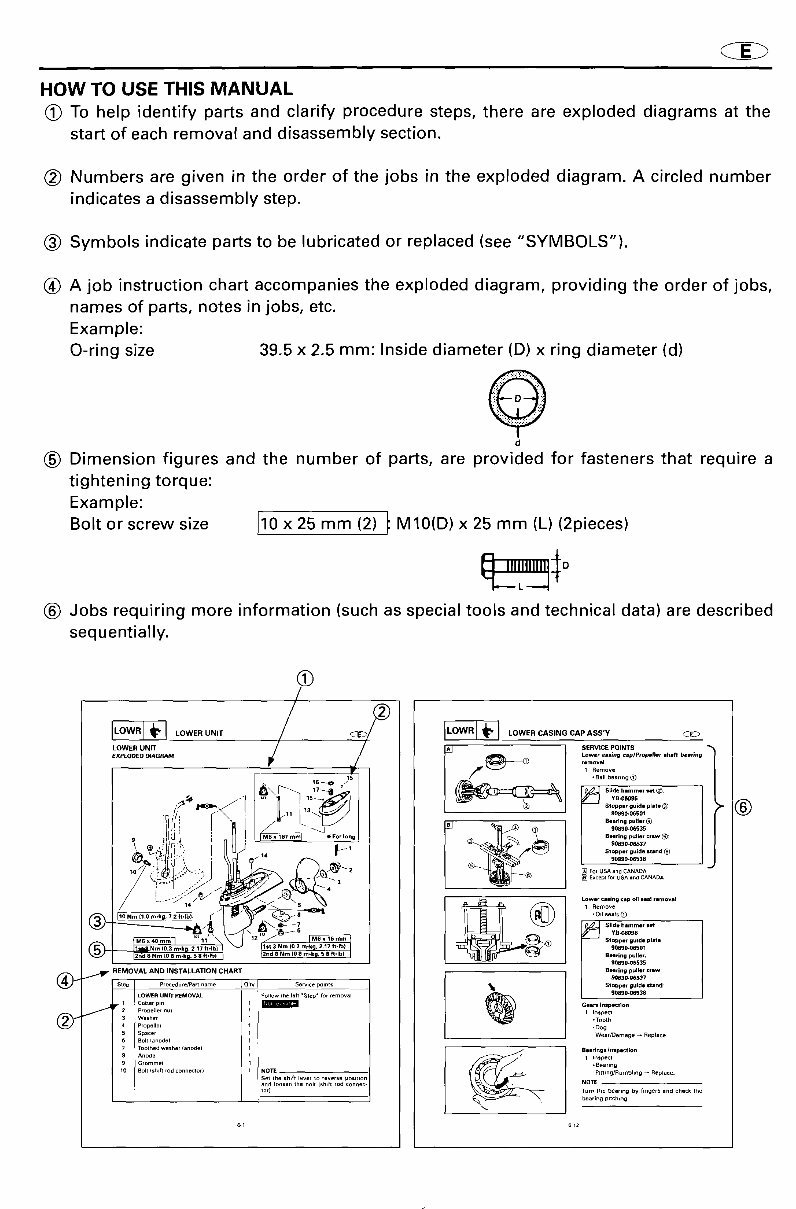
HOW TO USE THIS MANUAL (_ To help identify parts and clarify procedure steps, there are exploded diagrams atthe start of each removal and disassembly section. (_ Numbers are given in the order of the jobs in the exploded diagram. A circled number indicates a disassembly step. (_ Symbols indicate parts to be lubricated or replaced (see "SYMBOLS"). (_) A job instruction chart accompanies the exploded diagram, providing the order of jobs, names of parts, notes in jobs, etc. Example: O-ring size 39.5 x 2.5 mm: Inside diameter (D) x ring diameter (d) d (_) Dimension figures and the number of parts, are provided for fasteners that require a tightening torque: Example: Bolt or screw size 10 x 25 mm (2) t M10(D) x 25 mm (L) (2pieces) (_) Jobs requiring more information {such as special tools and technical data) are described sequentially. 'OWr-- 'OWE. V.,T // 'OW .OWE. CA,,. CAPA..y EXPLODED_AGRAM Lower cesJng_plPropelJer gha_ beefing removal 1 Remove 15 -Ball bearing1_ S........ ide plate0) _' (_ '1', r' /11 90890.06501 Stopper guide stand_.) F [] ForUSA aadCANADA L ,' ... _,-' ..J [] Excep_ for USAandCANADA (_ i_m'k" ........ )_' _ 12 i;f_3st Nm (3 ri_.k .O _6_;_ '_ ............. .... 9Q890.06501 12rid8 Nm (g a re.kg.58ft.lb) _2nd8 Nm (08 m'kU. 5 8 fi'lb) I Bearing puller. 90sg0_ss3s REMOVAL AND INSTALLATION CHART Bearing puller crew _0agc,oa537 LOWERUNIT REMOVAL ¢ollew theleh 'Step' for removal 9_890'0_38 r 1 Cotter pin / GII_ inspection 2 pr°peUer nUT 1InspeCl 3 Washer *Tooth .Dog 4 propeller 1 5 Spacer 1 Wear_)emage _ Replace 6 Bolt lanode) 1 7 Tootheawasher (anodei 1 _ Bearings Inlpection 8 Anode 1 _ 1 Inspect 9 Grommet 1 .Bearing 10 editIShlftrodconne_or) 1 NOTE pitting/Rumbling _ Replace. Set the shift lever to reverse poal_lOn and loosenthe bolt tsh,ft rod connec- NOI_ tor) Turn the bearing by fingers and checkIhe . beari_g pitching _1 612
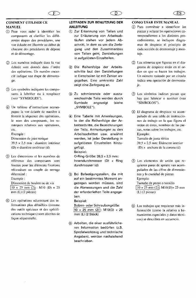
CED <2iX) ClX) COMMENT UTILISER CE LEITFADEN ZUR BENUTZUNG DER COMO USAR ESTE MANUAL MANUEL ANLEITUNG (_) Para contribuir a identificar las (_ Pour vous aider b. identifier les (_) Zur Erkennung yon Teilen und piezas y aclarar las operaciones co- composants et clarifier les diff,- zur Erl_uterung yon Arbeitsab- rrespondientes a los distintos pro- rentes _tapes desprocedures, one I_ufen stehen vor jedem Ab- cedimientos, seincluyen diagra- rue 6clatOeest illustr_e au d_but de schnitt, in dem es um die Zerle- mas de despiece al principio de chacune des proc_Sdures de dOpose gung und den Zusammenbau cada secci6n de desmontaje y mon- et de d{Smontage, yon Teilen geht, Darstellungen taje. in aufgelOsten Einzelteilen. (_) Les numOros indiqu_s dansla rue (_) Los nfmeros quefiguran en el dia- {Sclat_Sesont donmSs dans l'ordre (_) Die Reihenfolge der Arbeits- grama de despiece estfin en el or- des operations. Un numOro encer- schritte laut den Darstellungen den en que se hacen los trabajos. cl_ indique une {Stape de d_monta- in Einzelteilen ist mit Zahlen an- Un nfimero rodeado pot un cfrculo ge. gegeben. Eine umkreiste Zahl indicauna operaci6nde desmonta- zeigt eine Zerlegung an. je. (_) Les symboles indiquent les compo- sams h lubrifier ou h remplacer (_) Zu sehmierende oder auszu- (_) Los sfmbolos indican piezas que (voir"SYMBOLES"). wechselnde Teile werden durch hay que lubricar o sustituir (yea Symbole angezeigt (siehe "SIMBOLOS"). (_) Un tableau d'instructions accom- ,,SYMBOLE"). pagne la rue ficlatdede mani_reh Q E1diagramade despieceva acom- fournir la s_Squence des operations. (_) Eine Tabelle mit Anweisungen, pafiado de una tabla de instruccio- le nora des composants, les re- in der die Reihenfolge der Ar- nes de trabajo en la que figura el marques relatives aux op6rations, beitssehritte, die Bezeichnungen orden de _Sstos, nombres de las pie- etc. der Teile, Anmerkungen zu den zas, notas sobre los trabajos, etc. Exemple: Arbeitsschritten usw. erw/ihnt Ejemplo: Dimension de joint torique werden, ist jeder Darstellung in Tamafio de junta t6rica 39,5 x 2,5 nlm: diam_tre int_rieur aufgelOsten Einzelteilen hinzu- 39,5 x 2,5 mm: Dk4metro interior (D)x diam_treextdrieur(d) geffigt. (D)x anchurade lacorona(d) Beispiel: (_ Les dimensions et les numfiros de O-Ring-Gr6Be: 39,5 x 2,5 mm: rOf_rence des composants sont Innendurchmesser (D) x Ring (_) Los elementos de uni6n que re- fournis pour les d_ments fixations durchmesser (d) quieren pares de apriete van acom- n_cessitantun couple de serrage pafiadosde las cifrasde dimensio- d_termim5: (_) Bei Befestigungsteilen, die mit nes y la cantidad de piezas. Exemple: auf ein bestimmtes Moment an- Ejemplo: Dimension de boulon ou de vis gezogen werden mfissen, sind Tamafio de perno o tornillo [10 x 25 mm (2)J: M10 (D) x 25 die Abmessungen und die Zahl [10 x 25 mm (2)J:M10(D)x25 mm mm(L) (2 pi_ces) der erforderlichen Teile angege- (L) (2 piezas) ben. (_) Les operations ndcessitant des in- Beispieh formations plus d_taillOes (comme Bolzen- oder Sehraubengr6_e: (_ Los trabajos que requieran m_.s in- des outils spOciaux et des sp_cifi- [10 x 25 mm (2)J: MIO(D) x 25 formaci6n (como la relativa a he- cations techniques) sont d_crites de mm (L) (2 StOck) rramientas especiales y datos t_cni- fagon sdquentielle, cos) se describen en secuencia. (_) Arbeiten, die einer ausfOhrliche- ren Information bedQrfen (z.B. Spezialwerkzeug und technische Angaben), werden nachstehend beschrieben.
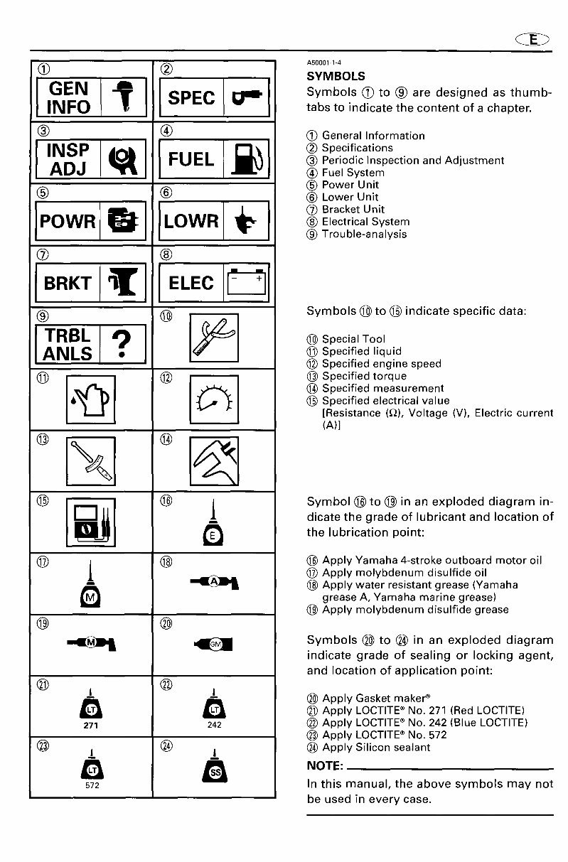
_ A_000114 SYMBOLS IGEN-_, [INFO SPEC [ _[_'l Symbols (_to (_ are designed as thumb- tabs to indicate the content of a chapter. (_) (_ (_ General Information i..s, s eci i atio s ADJ ® Periodic Inspection and Adjustment _) Fuel System (_) Power Unit (_ (_ _ Lower Unit POWR ®Electrical System Trouble-analysis ® ® (_ ® Symbols @ to O indicate specificdata: i....?1 (_) Specified liquid ANLS ® Specified engine speed _ (_ Specified torque (_) (_) (_)Specified measurement i_ (_ Specifiedelectrical value [Resistance (_), Voltage (V), Electric current (A)] ® [_! ® Symbol ® to ® in an exploded diagram in- I dicate the grade of lubricant and location of the lubrication point: (_) / (_) (_ Apply Yamaha4-stroke outboard motor oil t @ Apply molybdenum disulfide oil _ (_) Apply water resistant grease (Yamaha grease A, Yamaha marine grease) (_) Apply molybdenum disulfide grease ® ® _ Symbols® to (_)in an exploded diagram indicate grade of sealing or locking agent, and location of application point: ® ® 1_ ,_ (_) Apply Gasket maker ® (_) Apply LOCTITE ®No. 271 (Red LOCTITE) 271 242 _ Apply LOCTITE®No. 242 (Blue LOCTITE) (_) Apply LOCTITE ® No. 572 (_) (_ _ Apply Silicon sealant 572 In this manual, the above symbols may not be used in every case.
For your car repair needs, we offer the Yamaha OEM Service Manual for 1999-2009 4hp_F4_4-stroke models, manual number LIT-18616-01-79, spanning 154 pages. This comprehensive manual is recommended by Yamaha tech pubs for all models of the specified years.
General Information
Periodic Inspection and Adjustments
Fuel System
Power Unit
Lower Unit
Electrical System
Bracket Unit
Specifications
Troubleshooting
Many subsections of the above sections
The manual includes detailed wiring and circuit diagrams, illustrations, photos, exploded views, step-by-step instructions, diagnostics, and more. It is available in a file format compatible with all versions of Windows and Mac, and is in English. Adobe Reader is required for access.
This manual is invaluable for both professional mechanics and DIY enthusiasts, offering savings on dealer labor costs and providing essential guidance for maintenance tasks. Don't miss out on this essential resource for your car repair needs.