


40C
50C
SERVICE MANUAL
63B-28197-1F-11 LIT-18616-02-65
*LIT186160265*

E
NOTICE
This manual has been prepared by Yamaha primarily for use by Yamaha dealers and their
trained mechanics when performing maintenance procedures and repairs to Yamaha equip-
ment. It has been written to suit the needs of persons who have a basic understanding of the
mechanical and electrical concepts and procedures inherent in the work, for without such
knowledge attempted repairs or service to the equipment could render it unsafe or unfit for
use.
Because Yamaha has a policy of continuously improving its products, models may differ in
detail from the descriptions and illustrations given in this publication. Use only the latest edi-
tion of this manual. Authorized Yamaha dealers are notified periodically of modifications and
significant changes in specifications and procedures, and these are incorporated in succes-
sive editions of this manual.
40C, 50C
SERVICE MANUAL
©2003 by Yamaha Motor Corporation, USA
1st Edition, July 2003
All rights reserved.
Any reprinting or unauthorized use
without the written permission of
Yamaha Motor Corporation, USA
is expressly prohibited.
Printed in USA
LIT-18616-02-65
E
HOW TO USE THIS MANUAL
MANUAL FORMAT
All of the procedures in this manual are organized in a sequential, step-by-step format. The
information has been complied to provide the mechanic with an easy to read, handy refer-
ence that contains comprehensive explanations of all disassembly, repair, assembly, and
inspection operations.
In this revised format, the condition of a faulty component will precede an arrow symbol and
the course of action required will follow the symbol, e.g.,
● Bearings
Pitting/Damage → Replace.
To assist you to find your way about this manual, the Section Title and Major Heading is
given at the head of every page.
An Index to contents is provided on the first page of each Section.
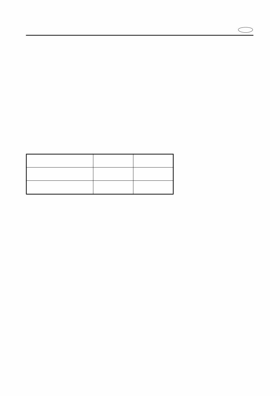
MODEL INDICATION
Multiple models are shown in this manual. These indications are noted as follows.
THE ILLUSTRATIONS
Some illustrations in this manual may differ from the model you have. This is because a pro-
cedure described may relate to several models, though only one may be illustrated. (The
name of model described will be mentioned in the description).
REFERENCES
These have been kept to a minimum; however, when you are referred to another section of
the manual, you are told the page number to go to.
Model name 40VETO 50HETO
USA and
CANADA name
40TR 50TR
Indication 40VETO 50HETO
E
WARNINGS, CAUTIONS AND NOTES
Attention is drawn to the various Warnings, Cautions and Notes which distinguish important
information in this manual in the following ways.
The Safety Alert Symbol means ATTENTION! BECOME ALERT! YOUR SAFETY IS
INVOLVED!
WARNING
Failure to follow WARNING instructions could result in severe injury or death to the machine
operator, a bystander, or a person inspecting or repairing the outboard motor.
CAUTION:
A CAUTION indicates special precautions that must be taken to avoid damage to the out-
board motor.
NOTE:
A NOTE provides key information to make procedures easier or clearer.
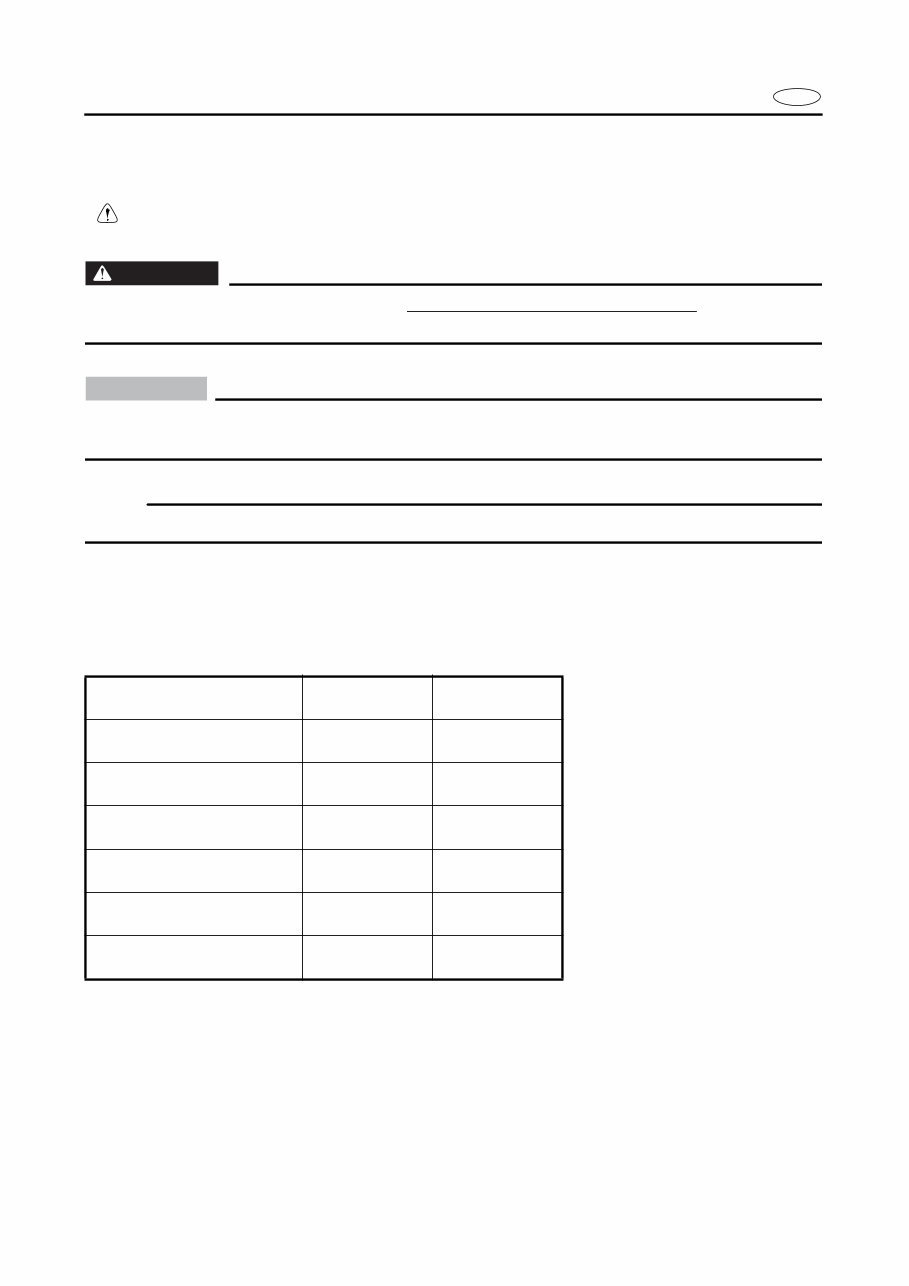
SPECIFICATIONS
These are given in bold type at each procedure. It is not necessary to leave the section deal-
ing with the procedure in order to look up the specifications.
It is important to note the differences ispecifications of models. When a procedure relates to
more than one model, the main differences in specifications will be shown in a following table.
Model name 40VETO 50HETO
Starting system Electric Electric
Control system Remote Remote
Trim/Tilt system PTT PTT
Lubrication system Oil injection Oil injection
Warning indicator lamp 3 —
Enrichment system Prime Start Prime Start
E
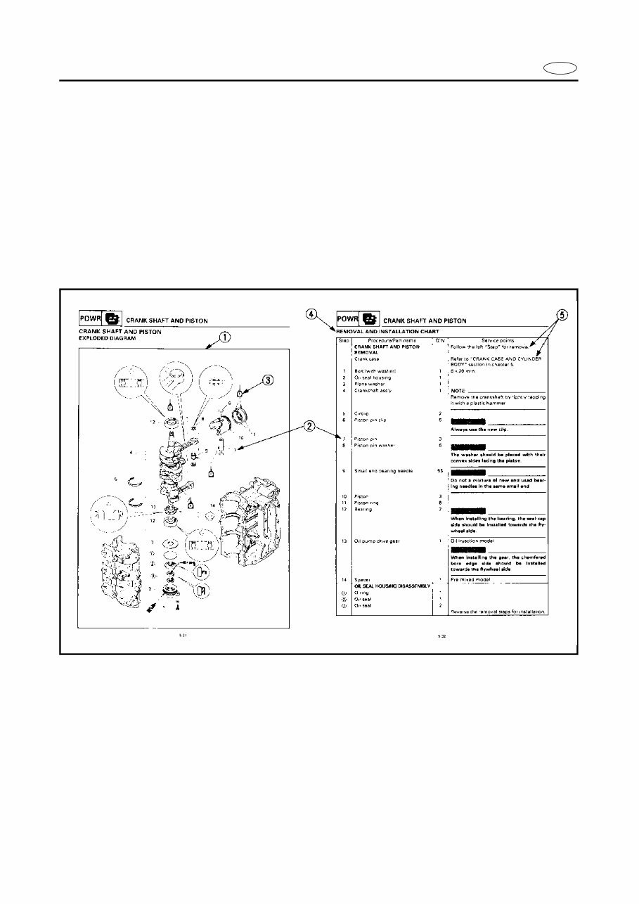
HOW TO READ DESCRIPTIONS
1. A disassembly installation job mainly consists of the exploded diagram 1.
2. The numerical figures represented by the number 2 indicates the order of the job steps.
3. The symbols represented by the number 3 indicates the contents and notes of the job.
For the meanings of the symbols, refer to the next page(s).
4. The REMOVAL AND INSTALLATION CHART 4 is attached to the exploded diagram and
explains the job steps, part names, notes for the jobs, etc.
5. The SERVICE POINTS, other than the exploded diagram, explains in detail the items diffi-
cult to explain in the exploded diagram or REMOVAL AND INSTALLATION CHART, the
Service points requiring the detailed description 5 , etc.
E
A50001-1-4
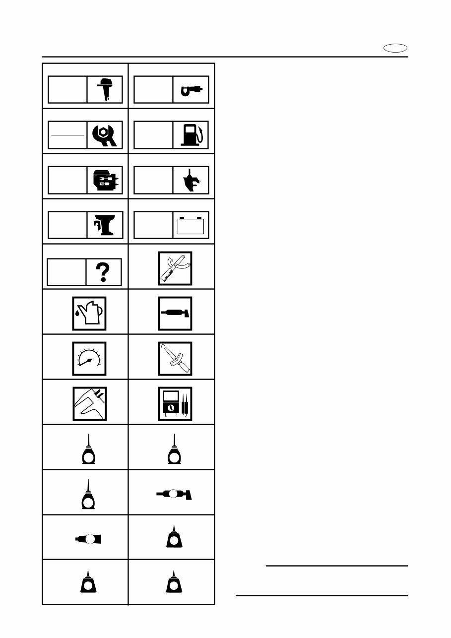
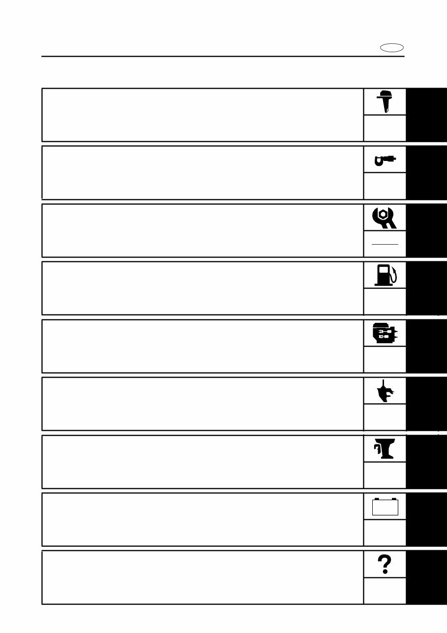
SYMBOLS
Symbols 1 to 9 are designed as thumb-
tabs to indicate the content of a chapter.
1 General Information
2 Specifications
3 Periodic Inspection and Adjustment
4 Fuel System
5 Power Unit
6 Lower Unit
7 Bracket Unit
8 Electrical System
9 Trouble-analysis
Symbols 0 to F indicate specific data:
0 Special tool
A Specified liquid
B Specified grease
C Specified engine speed
D Specified torque
E Specified measurement
F Specified electrical value
[Resistance (Ω), Voltage (V), Electric current
(A)]
Symbol G to J in an exploded diagram
indicate grade of lubricant and location of
lubrication point:
G Apply Yamaha 2-stroke outboard motor oil
H Apply Yamaha gear-case lubricant
I Apply molybdenum disulfide oil
J Apply water resistant grease (Yamaha
grease A, Yamaha marine grease)
Symbols K to N in an exploded diagram
indicate grade of sealing or locking agent,
and location of application point:
K Apply Gasket maker
®
L Apply LOCTITE
®
No. 271 (Red LOCTITE)
M Apply LOCTITE
®
No. 242 (Blue LOCTITE)
N Apply LOCTITE
®
No. 572
NOTE:
In this manual, the above symbols may not
be used in every case.
1 2
3 4
5 6
7 8
9 0
A B
C D
E F
G H
I J
K L
M N
GEN
INFO
SPEC
INSP
ADJ
FUEL
POWR LOWR
BRKT
– +
ELEC
TRBL
ANLS
T
R
.
.
E G
M
A
GM
271
LT
242
LT
572
LT
E
INDEX
GENERAL INFORMATION
1
SPECIFICATIONS
2
SPEC
PERIODIC INSPECTION AND
ADJUSTMENT
3
FUEL SYSTEM
4
FUEL
POWER UNIT
5
POWR
LOWER UNIT
6
LOWER
BRACKET UNIT
7
BRKT
ELECTRICAL SYSTEM
8
ELEC
TROUBLE-ANALYSIS
9
GEN
INFO
INSP
ADJ
– +
TRBL
ANLS
A30000-0
E
1
2
3
4
5
6
7
8
9
GEN
INFO
CHAPTER 1
GENERAL INFORMATION
IDENTIFICATION............................................................................................. 1-1
SERIAL NUMBER ..................................................................................... 1-1
STARTING SERIAL NUMBERS ............................................................... 1-1
SAFETY WHILE WORKING ............................................................................ 1-2
FIRE PREVENTION ................................................................................... 1-2
VENTILATION........................................................................................... 1-2
SELF-PROTECTION .................................................................................. 1-2
OILS, GREASES AND SEALING FLUIDS ................................................ 1-2
GOOD WORKING PRACTICES ................................................................ 1-3
DISASSEMBLY AND ASSEMBLY ........................................................... 1-4
SPECIAL TOOLS ............................................................................................. 1-5
MEASURING ............................................................................................ 1-6
REMOVAL AND INSTALLATION ............................................................ 1-8
1-1
GEN
INFO
E
IDENTIFICATION
A60000-1*
IDENTIFICATION
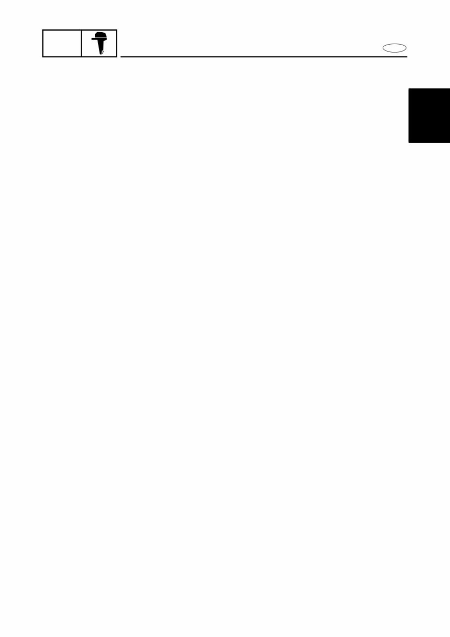
SERIAL NUMBER
The serial number of the outboard motor is
stamped on a plate attached to the port side
of the clamp bracket.
NOTE:
As an antitheft measure, a special label on
which the outboard motor serial number is
stamped is bonded to the portside of the
clamp bracket. The label is specially treated
so that peeling it off causes cracks across
the serial number.
1 Model name
2 Approved model code
3 Transom height
4 Serial number
STARTING SERIAL NUMBERS
The starting serial number blocks are as fol-
lows:
Model
Approved
model code
Starting
serial No.
40TR 6H4 L: 1005165 ~
50TR 6H5 L: 1004305 ~
1-2
GEN
INFO
E
SAFETY WHILE WORKING
SAFETY WHILE WORKING
The procedures given in this manual are
those recommended by Yamaha to be fol-
lowed by Yamaha dealers and their
mechanics.
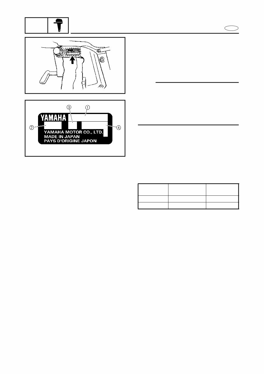
FIRE PREVENTION
Gasoline (petrol) is highly flammable.
Petroleum vapor is explosive if ignited.
Do not smoke while handling, and keep it
away from heat, sparks, and open flames.
VENTILATION
Petroleum vapor is heavier than air and is
deadly if inhaled in large quantities. Engine
exhaust gases are harmful to breathe.
When test-running an engine indoors,
maintain good ventilation.
SELF-PROTECTION
Protect your eyes with suitable safety
glasses or safety goggles when using com-
pressed air, when grinding or when doing
any operation which may cause particles to
fly off. Protect hands and feet by wearing
safety gloves or protective shoes if appro-
priate to the work you are doing.
OILS, GREASES AND SEALING
FLUIDS
Use only genuine Yamaha oils, greases and
sealing fluids or those recommended by
Yamaha.
You're Reading a Preview
What's Included?
Fast Download Speeds
Online & Offline Access
Access PDF Contents & Bookmarks
Full Search Facility
Print one or all pages of your manual
$31.99
Yamaha Outboard 40C 50C 40TLRD 50TLRD* Factory Service / Repair/ Workshop Manual !
Viewed 63 Times Today

What's Included?
Fast Download Speeds
Online & Offline Access
Access PDF Contents & Bookmarks
Full Search Facility
Print one or all pages of your manual
$31.99

Secure transaction
What's Included?
Fast Download Speeds
Online & Offline Access
Access PDF Contents & Bookmarks
Full Search Facility
Print one or all pages of your manual
This workshop manual provides maintenance and repair procedures for the Yamaha Outboard 40C 50C 40TLRD 50TLRD models. It is a valuable resource for both professional mechanics and DIY enthusiasts, offering step-by-step instructions and detailed diagrams for efficient completion of all repair procedures.
The manual covers the following models:
- Yamaha 40VETO 50HETO
- Yamaha 40TR 50TR
Service Repair Manual Covers:
- General Information
- Specifications
- Periodic Check And Adjustment
- Fuel System
- Power Unit
- Lower Unit
- Bracket Unit
- Electrical System
- Trouble Analysis
This manual is available for instant access without any shipping costs. It is compatible with all versions of Windows & Mac and can be viewed using Adobe Reader & Win. The language of the manual is English, and all pages are printable for convenience.


