

1990-1997 Yamaha 40hp 2-Stroke Outboard Service & Repair Manual
What's Included?
Fast Download Speeds
Online & Offline Access
Access PDF Contents & Bookmarks
Full Search Facility
Print one or all pages of your manual

1990 - 1997
OUTBOARD
SERVICE MANUAL
Model : C40ELRP, C40ELRQ, C40ELRR,
C40ELRS, C40ELRT, C40ELRU, C40ELRV,
C40MLHQ, C40MLHR, C40MLHS,
C40MLHT, C40MLHU, C40MLHV,
C40MSHQ, C40MSHR, C40MSHS,
C40MSHT, C40PLRU, C40PLRV, CV40ELD
6R6281972011 *6R6281972011*
AIO000-O*
CV40
SERVICE MANUAL
© 1989 Yamaha Motor Co., Ltd.
1st Edition, December 1989
All rights reserved.
No part of this publication may be
reproduced or transmitted in any form
or by any means including photocopying
and recording without the written
permission of the copyright holder.
Such written permission must also be
obtained before any part of this
publication is stored in a retrieval
system of any nature.
Printed in Japan
PIN 8R6-28197.20.11
A20000-0
NOTICE
This manualhas been prepared by theYamahaMotor Company primarily for use by Yamahadeal-
ersand their trained mechanics when performing maintenance proceduresand repairs to
Yamaha equipment.Ithas been written to suit theneeds of persons who have a basic under-
standing of the mechanical and electrical conceptsand proceduresinherent in the work, for without
such knowledge attempted repairsor serviceto theequipment could render it unsafeor unfit for use.
Because the Yamaha Motor Company Ltd hasa policy ofcontinuously improving its products,
models may differ in detail from the descriptions and illustrations given in this publication. Use
only the latest edition of this manual.Authorised Yamahadealersare notified periodically of modifi-
cations and significant changes in specifications and procedures, and these are incorporated in
successive editions of this manual.

A30000-0
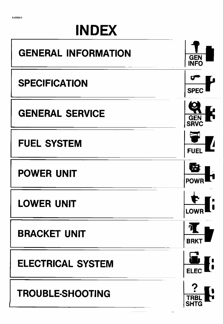
INDEX
GENERAL INFORMATION -ir
GEN
INFO
g..
SPECIFICATION SC-E'C _'J
GENERAL SERVICE _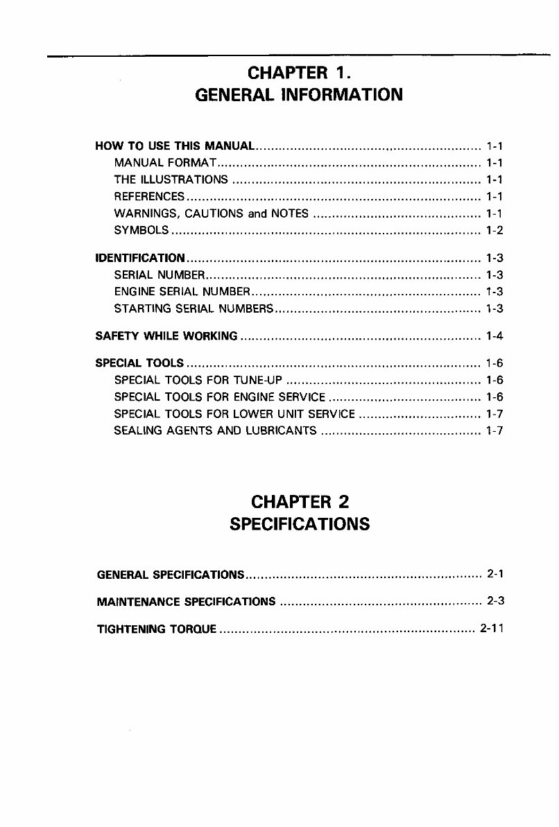
CHAPTER 1.
GENERAL INFORMATION
HOWTO USE THIS MANUAL ........................................................... 1-1
MANUAL FORMAT ..................................................................... 1-1
THE ILLUSTRATIONS ................................................................. 1-1
REFERENCES............................................................................. 1-1
WARNINGS, CAUTIONS and NOTES ............................................ 1-1
SYMBOLS ................................................................................. 1-2
IDENTIFICATION ............................................................................. 1-3
SERIAL NUMBER ........................................................................ 1-3
ENGINE SERIAL NUMBER ............................................................ 1-3
STARTING SERIAL NUMBERS ...................................................... 1-3
SAFETY WHILE WORKING ............................................................... 1-4
SPECIAL TOOLS ............................................................................. 1-6
SPECIAL TOOLS FOR TUNE-UP ................................................... 1-6
SPECIAL TOOLS FOR ENGINE SERVICE ........................................ 1-6
SPECIAL TOOLS FOR LOWER UNIT SERVICE ................................ 1-7
SEALING AGENTS ANDLUBRICANTS .......................................... 1-7
CHAPTER 2
SPECIFICATIONS
GENERAL SPECIFICATIONS .............................................................. 2-1
MAINTENANCE SPECIFICATIONS ..................................................... 2-3
TIGHTENING TORQUE ................................................................... 2-1 1

CHAPTER 3
GENERAL SERVICE
PREDELIVERY SERVICE ............................................................................... 3-1
CONTENTS ............................................................................................... 3-1
ELECTRIC WIRING ..................................................................................3-2
FUELLINE ................................................................................................ 3-3
GEAROILLEVEL .....................................................................................3-4
OPERATION OFCONTROLS AND MOVING PARTS .......................... 3-4
FUEL LEAKAGE ....................................................................................... 3-5
WATER LEAKAGE ...................................................................................3-5
EXHAUST LEAKAGE ............................................................................... 3-5
ENGINEAND LOWER UNIT NOISE ...................................................... 3-5
IDLE-SPEED.............................................................................................. 3-5
IGNITION TIMING ........................................ ' ........... '. ................................ 3-5
MOTOR EXTERIOR .................................................................................. 3-5
INSTRUCTING THE NEW OWNER ........................................................ 3-5
PERIODIC SERVICE ...................................................................................... 3-6
MAINTENANCE SCHEDULE ................................................................... 3-6
ANODE ...................................................................................................... 3-6
BATFERY................................................................................................... 3-7
CARBURETOR ...................i ...................................................................... 3-8
CARBURETOR LINK ADJUSTMENT ...................................................... 3-8
CHOKE SOLENOID .................................................................................. 3-8
CYLINDER HEADBOLTS, ENGINE MOUNTINGBOLTS, AND
FLYWHEELNUT ...................................................................................... 3-9
FUEL FILTER ............................................................................................ 3-9
FUEL TANK AND FUEL LINE ................................................................ 3-9
GEAROIL................................................................................................... 3-9
IDLE-SPEED.............................................................................................. 3-9
IGNITION TIMING ADJUSTMENT ........................................................ 3-10
PROPELLER ............................................................................................ 3-14
SPARK PLUG.......................................................................................... 3-15
START-IN-GEAR PROTECTION ADJUSTMENT .................................. 3-15
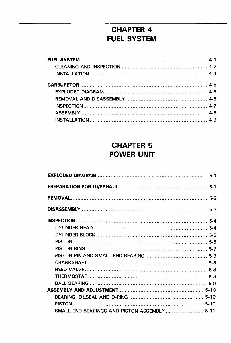
CHAPTER 4
FUEL SYSTEM
FUEL SYSTEM ................................................................................ 4-1
CLEANING AND INSPECTION ...................................................... 4-2
INSTALLATION .......................................................................... 4-4
CARBURETOR ................................................................................ 4-5
EXPLODED DIAGRAM ................................................................. 4-5
REMOVAL AND DISASSEMBLY ................................................... 4-6
INSPECTION .............................................................................. 4-7
ASSEMBLY ............................................................................... 4-8
INSTALLATION .......................................................................... 4-9
CHAPTER 5
POWER UNIT
EXPLODED DIAGRAM ..................................................................... 5-1
PREPARATION FOR OVERHAUL ........................................................ 5-1
REMOVAL ...................................................................................... 5-2
DISASSEMBLY ............................................................................... 5-3
INSPECTION ................................................................................... 5-4
CYLINDER HEAD .................. ; ..................................................... 5-4
CYLINDER BLOCK ...................................................................... 5-5
PISTON ..................................................................................... 5-6
PISTON RING ............................................................................ 5-7
PISTON PIN AND SMALL END BEARING ....................................... 5-8
CRANKSHAFT ........................................................................... 5-8
REED VALVE ............................................................................. 5-8
THERMOSTAT ........................................................................... 5-9
BALL BEARING .......................................................................... 5-9
ASSEMBLY AND ADJUSTMENT ..................................................... 5-10
BEARING, OILSEAL AND O-RING ............................................... 5-10
PISTON ................................................................................... 5-10
SMALL END BEARINGS AND PISTON ASSEMBLY ........................ 5-1 1
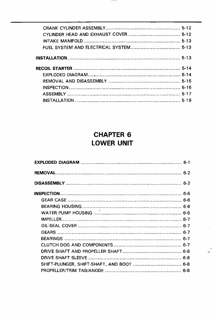
CRANK CYLINDER ASSEMBLY ................................................... 5-12
CYLINDER HEAD AND EXHAUST COVER .................................... 5-12
INTAKE MANIFOLD .................................................................. 5-1 3
FUEL SYSTEM AND ELECTRICAL SYSTEM .................................. 5-13
INSTALLATION ............................................................................. 5-1 3
RECOIL STARTER ......................................................................... 5-14
EXPLODED DIAGRAM ............................................................... 5-14
REMOVAL AND DISASSEMBLY ................................................. 5-1 5
INSPECTION ............................................................................ 5-1 6
ASSEMBLY ............................................................................. 5-1 7
INSTALLATION ........................................................................ 5-1 9
CHAPTER 6
LOWER UNIT
EXPLODED DIAGRAM ..................................................................... 6-1
REMOVAL ...................................................................................... 6-2
DISASSEMBLY ............................................................................... 6-2
INSPECTION ................................................................................... 6-6
GEAR CASE .............................................................................. 6-6
BEARING HOUSING .................................................................... 6-6
WATER PUMP HOUSING ............................................................ 6-6
IMPELLER .................................................................................. 6-7
OIL-SEAL COVER ....................................................................... 6-7
GEARS ..................................................................................... 6-7
BEARINGS ................................................................................ 6-7
CLUTCH DOG AND COMPONENTS .............................................. 6-7 i
DRIVE SHAFT AND PROPELLER SHAFT ........................................ 6-8 ,-
DRIVE SHAFT SLEEVE ................................................................ 6-8
SHIFT-PLUNGER, SHIFT-SHAFT, AND BOOT ................................. 6-8
PROPELLER/TRIM TAB/ANODE .................................................... 6-8
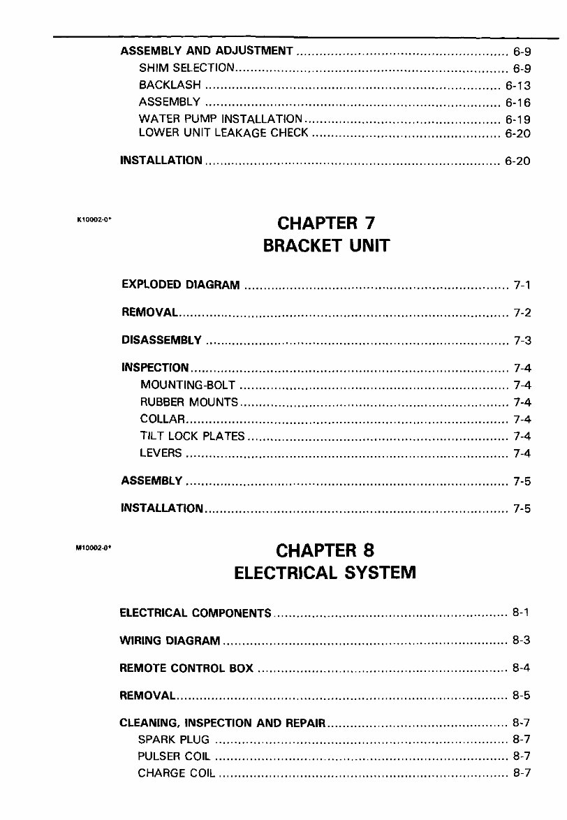
ASSEMBLY AND ADJUSTMENT ....................................................... 6-9
SHIMSELECTION ....................................................................... 6-9
BACKLASH ............................................................................. 6-13
ASSEMBLY ............................................................................. 6-16
WATERPUMP INSTALLATION ................................................... 6-19
LOWER UNITLEAKAGECHECK ................................................. 6-20
INSTALLATION ............................................................................. 6-20
K_ooo2o. CHAPTER 7
BRACKET UNIT
EXPLODED DIAGRAM ..................................................................... 7-1
REMOVAL ...................................................................................... 7-2
DISASSEMBLY ............................................................................... 7-3
INSPECTION ................................................................................... 7-4
MOUNTING-BOLT ...................................................................... 7-4
RUBBER MOUNTS ...................................................................... 7-4
COLLAR .................................................................................... 7-4
TILT LOCK PLATES .................................................................... 7-4
LEVERS .................................................................................... 7-4
ASSEMBLY .................................................................................... 7-5
INSTALLATION ............................................................................... 7-5
.,oooo. CHAPTER8
ELECTRICAL SYSTEM
ELECTRICAL COMPONENTS ............................................................. 8-1
WIRING DIAGRAM .......................................................................... 8-3
REMOTE CONTROLBOX ................................................................. 8-4
REMOVAL ...................................................................................... 8-5
CLEANING, INSPECTION AND REPAIR ............................................... 8-7
SPARK PLUG ............................................................................ 8-7
PULSER COIL ............................................................................ 8-7
CHARGECOIL ........................................................................... 8-7
You're Reading a Preview
What's Included?
Fast Download Speeds
Online & Offline Access
Access PDF Contents & Bookmarks
Full Search Facility
Print one or all pages of your manual
$39.99
Viewed 69 Times Today


Secure transaction
What's Included?
Fast Download Speeds
Online & Offline Access
Access PDF Contents & Bookmarks
Full Search Facility
Print one or all pages of your manual
$39.99
Get the 1990-1997 Yamaha 40hp 2-Stroke Outboard Service & Repair Manual for comprehensive guidance on repairs, servicing, and troubleshooting procedures. This professional manual is an invaluable resource for both professional mechanics and DIY enthusiasts. It contains detailed photos, diagrams, and step-by-step instructions to help you complete every job correctly.
Access the manual instantly on your computer, tablet, or smartphone. You have the flexibility to print out a single page or the entire manual. There are no limitations or trial periods; you can use this manual for life without the need to renew or pay any extra fees. It is fully compatible with all Windows and MAC computers.


