OUTBOARD / MOTEUR HORS-BORD SERVICE MANUAL / MANUEL D’ATELIER Model : PRO50LH 6H5281977100 *6H5281977100*
FOREWORD This Supplementary Service Manual has been prepared to introduce new service and new data for the Pro-50. For complete information on service procedures, it is necessary to use this Supplementary Service Manual together with following manual: I Service Manual 40N/40EN/50ETN: I (6H4-28197-70) I Pro-50 SUPPLEMENTARY SERVICE MANUAL @1986 by Yamaha Motor Co., Ltd. 1st Edition, September. 1986 All rights reserved. Any reprinting or unauthorized use without the written permission of Yamaha Motor Co., Ltd. is expressly prohibited. Printed in JAPAN
IT! × ill m Z iB m fll
NOTICE HOW TO USE THIS MANUAL This manual was written by the Yamaha Motor PARTICULARLY IMPORTANT IN FORMA- Company primarily for useby Yamaha dealers TION and their qualified mechanics. It is not possible This material is distinguished by the following to put an entire mechanic's education into one notation. manual, so it is assumed that personsusing this book to perform maintenance and repairs on NOTE: Yamaha outboard motors have a basic under- ANOTE provides key information to make pro- standing of the mechanical conceptsand pro- cedures easier or clearer. cedures inherent in outboard motors repair techrlology. Without such knowledge,attempted "CAUTION: repairs or service to this model may render it A CAUTION indicates special procedures that unfit to use and/or unsafe, must be followed to avoid damage to the out- board motors. Yamaha Motor Co., Ltd. is continually striving to improve all models manufactured by Yamaha. Modifications and significant changes in specifi- A WARNING indicates special procedures that cations or procedures will be forwarded to all must be followed to avoid injury to a outboard Authorized Yamaha dealers and will, where ap- motors operator or person inspecting or repair- plicable, appear in future editions of this ing theoutboardmotors. manual. MANUAL FORMAT All of the procedures in this manual are organiz- ed in a sequential, step-by-step format. SERVICE DEPT. The information has been complied to provide OVERSEASMARKETING DIVISION the mechanic with an easy to read, handy re- MARINE OPERATIONS ference that contains comprehensive explana- YAMAHA MOTOR CO., LTD. tions of all disassembly, repair, assembly, and inspection operations. In this revised format, the condition of a faulty component will precede an arrow symbol and the course of action required will follow the symbol, e.g., Bearings Pitting/Damage --. Replace. EXPLODED DIAGRAM Each chapter provides exploded diagrams before each disassembly section for ease in identifying correct disassembly and assembly procedures. OPERATING SEQUENCE Part numbers ((_), (_), (:_)...) in this manual indicate the sequence of disassembly, assembly, and inspection procedures.
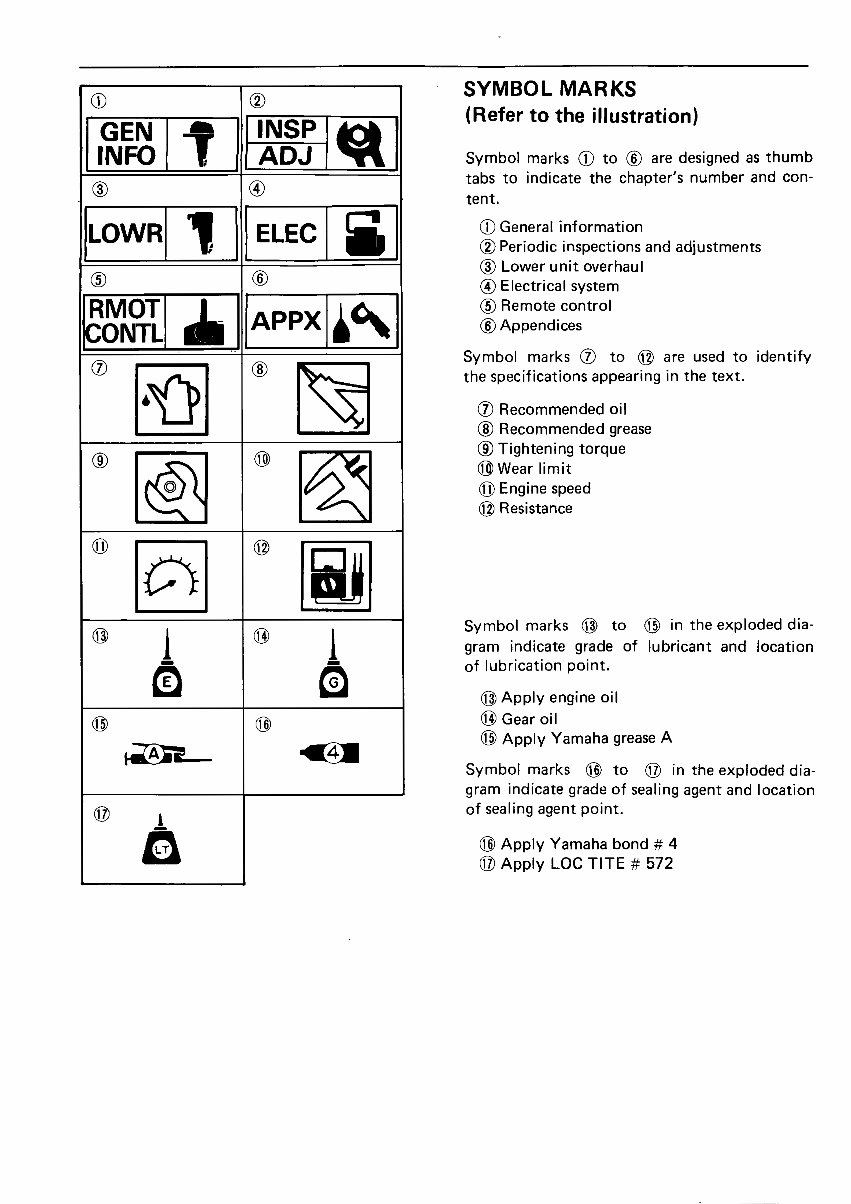
® GEN _ INSP _ (Refer to the illustration) INFO !. ADJ _ Symbol marks (_ to (_ are designed as thumb i tabs to indicate the chapter's number and con- (_) (_) tent. LOWR 1_ ELEC _ General information (_ Periodic inspectionsand adjustments (_ Lower unit overhaul (_ (_) _ Electrical system RMOT _kE_b, (_) Remote control Ii APPX II-- (_Appendices CONTL I I ' Symbol marks (_ to (_ are used to identify A_r"_ (_) _ thespecifications appearing in the text. i-!r._ _ _ Recommended oil , (_) Recommended grease (_ (_ _ _ Tightening torque (_ Wear limit O Engine speed (_) Resistance (_) j (_) i Symbol marks (_ to (_ in the exploded dia- gram indicate grade of lubricant and location of lubrication point. (_) Apply engine oil (_) (_) (_Gear oil (_) Apply Yamaha grease A Symbol marks (_) to (_) in the exploded dia- gram indicate grade of sealing agent and location (_) of sealing agent point. (_ Apply Yamaha bond # 4 @ Apply LOC TITE # 572
• INDEX GENERAL INFORMATION GEN INFO PERIODIC INSPECTIONS (I_ AND ADJUSTMENTS INSP ADJ ,fib LOWER UNIT OVERHAUL 1 LOWR ELECTRICAL SYSTEM ELEC REMOTE CONTROL RMOT CONTL APPENDICES &¢% APPX
I-fj • INFO I CHAPTE R 1 GENERAL INFORMATION OUTBOARD MOTOR IDENTIFICATION ...................................... 1- 1 MODEL AND SERIAL NUMBER .......................................... 1- 1 ENGINE SERIAL NUMBER .............................................. 1- 1 TECHNICAL FEATURES ................................................... 1- 2 CDI SYSTEM .......................................................... 1- 2 OIL INJECTION SYSTEM ................................................ 1- 3 POWER TRIM AND TILT ................................................ 1- 7 COOLING SYSTEM ........................................................ 1-11 SPECIAL TOOLS .......................................................... 1-12 FOR POWER TRIM AND TILT ............................................ 1-12 i i ! i .... i i i •
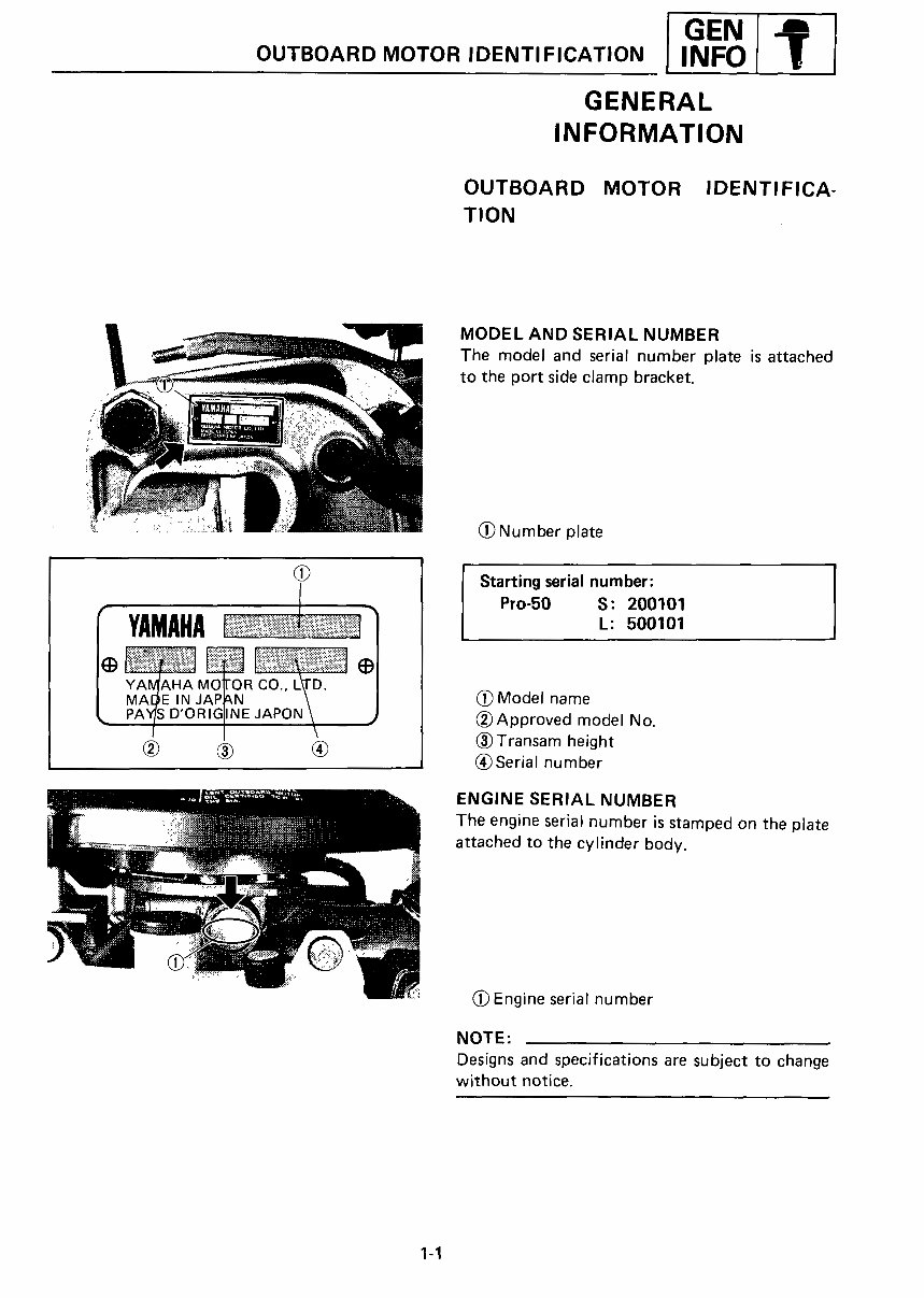
I GEN OUTBOARD MOTOR IDENTIFICATION J ,.ol?l GENERAL INFORMATION OUTBOARD MOTOR IDENTIFICA- TION MODEL AND SERIAL NUMBER The model and serial number plate is attached to the port side clamp bracket. "* _'"":",,:;,;,_,","_ (_ Number plate Starting serial number: I Pro-50 S: 200101 I_ .......?....., .......... ...............¢......v........,....... YAMAHA 1 ,: 5oo,o, YA4AHA MOTOR CO., L_I-D, ! MAeE IN JAPAN \ / _ Model name PA_S D'ORIG[INE JAPO_ J (_)Approved model No. (_) Transam height (_ _[) (_) (_ Serial number ENGINE SERIAL NUMBER The engine serial number is stamped on the plate attached to the cylinder body. (_) Engine serial number NOTE: Designs and specifications are subject to change without notice. 1-1
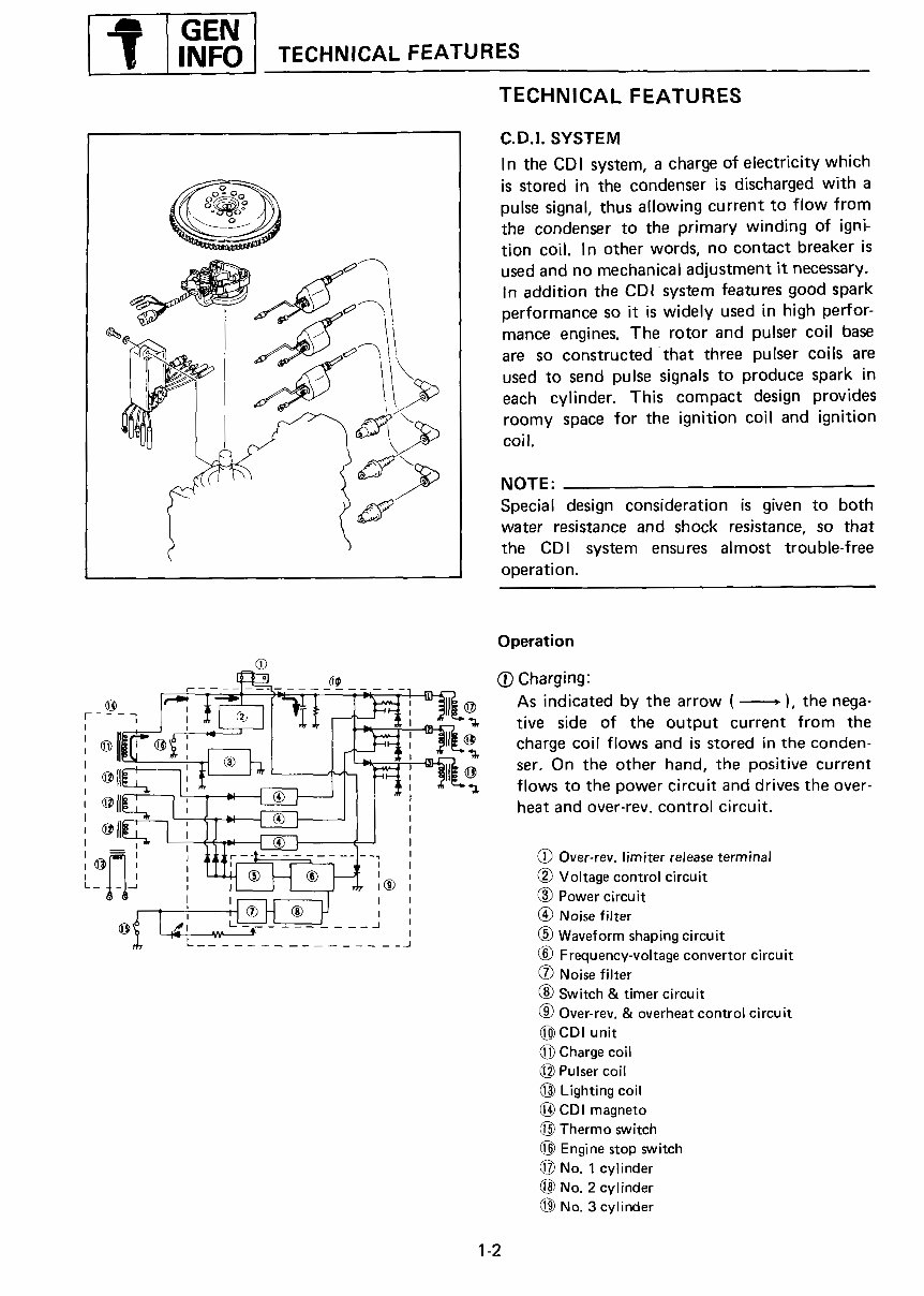
INFO TECHNICAL FEATURES TECHNICAL FEATURES C.D.I. SYSTEM In the CDI system, a charge of electricity which is stored in the condenser is discharged with a pulse signal, thus allowing current to flow from the condenser to the primary winding of igni- tion coil. In other words, no contact breaker is __,_ __'_i used and no mechanical adjustment it necessary. In addition the CDI system features good spark performance so it is widely used in high perfor- __ /i mance engines. The rotorand pulsercoil base _'_%---_"_ _ are so constructed that three pulser coils are __"_2_ ,__ / i,_<_ used to send pulse signals to produce spark in each cylinder. This compact design provides __k__ roomy space for the ignition coil and ignition coil. NOTE: Special design consideration is given to both water resistance and shock resistance, so that the CDI system ensures almost trouble-free operation. Operation _-. (_ Charging: -[F_='-_ _ -_- --_-- --'1 -?-_ I_-_ _,_-_[_t [_' E_ Asindicated by the arrow ( ,),thenega- 'B tive side of the output current from the (U)'_II_I ! _X?S [4__t_'_ ,?"_T__E_ charge coil flows and is stored inthe conden- @11_---_ I_'_ ser. On the other hand, the positive current ___. flows to the power circuit and drives the over- @Il heat and over-rev, control circuit. _ I - (_ Over-rev. limiter release terminal I [_ ® {_) Voltage control circuit i _-_ i (_ Power circuit @ -' ' __j (_) Waveform shapingcircuit Frequency-voltage convertor circuit Noise filter _) Switch & timer circuit L_ Over-rev.& overheat control circuit CDI unit {_) Chargecoil Pulser coil (_) Lighting coil CDI magneto Thermo switch Engine stop switch 1_ No.1cylinder No. 2 cylinder _) No. 3 cylinder 1-2
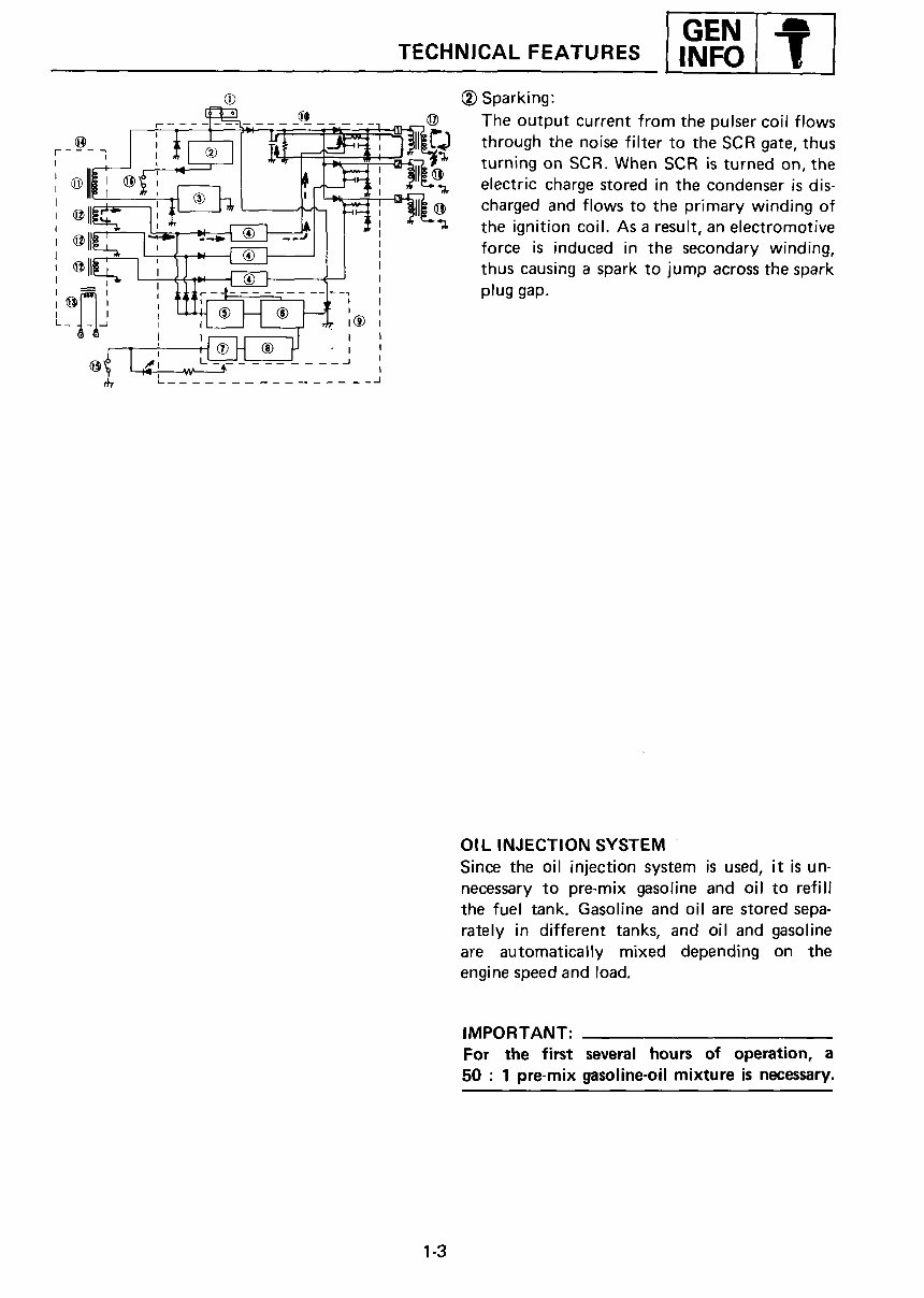
I GEN TECHNICAL FEATURES i ,..pi ? ! _ Sparking: ,- -_,=. _-_ --_.- -:. @ The output current from the pulser coil flows __ throughthe noisefilter to theSCRgate,thus ___J iI _,_L, I _ '[__ turning on SCR. When SCR is turned on, the @ electric chargestoredin the condenser is dis- I_ --'Il' the ignition coil. Asaresult, anelectromotiv @"_-_ I-Jll_--_--]_"_i_-'' force is induced in the secondary winding, _lli-_-_-I _l__ i_ J _ thus causing a spark to jump across the spark ' _1 ' 0 _ _ -' -' PI L INJECTION SYSTEM Since the oil injection system is used, it is un- necessary to pre-mix gasoline and oil to refill the fuel tank. Gasoline and oil are storedsepa- rately in different tanks, and oil and gasoline are automatically mixed depending on the engine speed and load. IMPORTANT: For the first several hours of operation, a 50: I pre-mix gasoline-oil mixture is necessary. 1-3
Our informative shop, service, repair manual, owner's manuals, and parts catalogs contain all the information you'll need to perform repairs, look up parts, or do routine maintenance on your machine. They include topics such as:
General Information
Routine Maintenance
Engine Removal and Installation
Fuel System
Lubrication and Cooling System
Engine Specifications
Transmission, Drive Chain & Sprockets
Steering System
Shocks
Body Work
Intake & Exhaust
Electrical System
Advanced Troubleshooting
With our manuals, find the page pertaining to your job, print it off, and get working on your project. No more ruining your expensive paper shop manual with grease and dirt.
Broken down on the trail or site and have a smartphone? What a cool way to find your problem and fix it, no downtime on the job site. With our manuals, you instantly have access to the material needed to get you running again.
Our entire manual collection comes with a lifetime protection policy. If lost or damaged, simply contact us, and we'll replace it free of charge for life.
We provide various service manuals, workshop manuals, repair manuals, owner's manuals, parts catalogs, and other various manuals, all in an electronic format.
UTVs, motorcycles, ATVs, quads, snowmobiles, Seadoo, equipment, small engines, inboards, outboards, and more.
Instant access with no shipping cost. Get a manual now, so no waiting, repair it now.
If you are looking for a specific manual and cannot find it or do not see it listed, then contact our customer support team via the contact us link above with details of the required manual, and we will do our absolute best to find and list it for you.