


SERVICE MANUAL
LIT-18616-03-08 6BJ-28197-1K-11
F300
LF300
F350
LF350
NOTICE
This manual has been prepared by Yamaha primarily for use by Yamaha dealers and their trained
mechanics when performing maintenance procedures and repairs to Yamaha equipment. It has
been written to suit the needs of persons who have the Bronze Technical Certificate of YTA (Yamaha
Technical Academy) marine or the equivalent basic understanding of the mechanical and electrical
concepts and procedures inherent in the work, for without such knowledge attempted repairs or ser-
vice to the equipment could render it unsafe or unfit for use.
Because Yamaha has a policy of continuously improving its products, models may differ in detail
from the descriptions and illustrations given in this publication. Use only the latest edition of this
manual. Authorized Yamaha dealers are notified periodically of modifications and significant
changes in specifications and procedures, and these are incorporated in successive editions of this
manual.
Important information
Particularly important information is distinguished in this manual by the following notations:
The Safety Alert Symbol means ATTENTION! BECOME ALERT! YOUR SAFETY IS
INVOLVED!
WARNING
Failure to follow WARNING instructions could result in severe injury or death to the machine
operator, a bystander, or a person inspecting or repairing the outboard motor.
CAUTION:
A CAUTION indicates special precautions that must be taken to avoid damage to the out-
board motor.
NOTE:
A NOTE provides key information to make procedures easier or clearer.
F300, LF300, F350, LF350
SERVICE MANUAL
©2007 by Yamaha Motor Corporation, U.S.A.
1st Edition, February 2008
All rights reserved.
Any reprinting or unauthorized use
without the written permission of
Yamaha Motor Corporation, U.S.A.
is expressly prohibited.
Printed in U.S.A.
LIT-18616-03-08
0
1
2
3
4
5
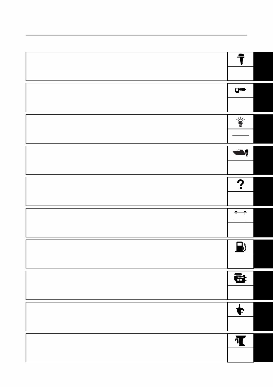
General information
Specification
Technical features and description
Rigging information
Troubleshooting
Electrical system
6
7
8
9
Fuel system
Power unit
Lower unit
Bracket unit
GEN
INFO
SPEC
TECH
FEA
RIG
GING
ELEC
FUEL
POWR
LOWR
BRKT
TRBL
SHTG
Contents

10
Maintenance
Index
Appendix
MNT
Contents

GEN
INFO
6BJ1K11
0
2
3
4
5
6
7
8
9
General information 0
Safety while working ..................................................................................... 0-1
Fire prevention .......................................................................................... 0-1
Ventilation ................................................................................................. 0-1
Self-protection .......................................................................................... 0-1
Part, lubricant, and sealant ....................................................................... 0-1
Special service tool ................................................................................... 0-2
Tightening torque ...................................................................................... 0-2
Non-reusable part ..................................................................................... 0-2
Disassembly and assembly ...................................................................... 0-2
How to use this manual ................................................................................ 0-3
Manual format ........................................................................................... 0-3
Symbol ...................................................................................................... 0-4
Abbreviation .............................................................................................. 0-5
Model features ............................................................................................... 0-7
General feature ......................................................................................... 0-7
Model designation .................................................................................... 0-8
Serial number ........................................................................................... 0-8
Special service tool ...................................................................................... 0-9
0-1 6BJ1K11
GEN
INFO
General information
Safety while working
To prevent an accident or injury and to
ensure quality service, follow the safety pro-
cedures provided below.
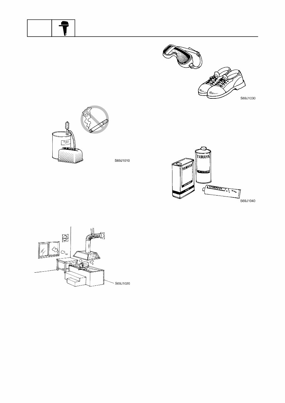
Fire prevention
Gasoline is highly flammable.
Keep gasoline and all flammable products
away from heat, sparks, and open flames.
Ventilation
Gasoline vapor and exhaust gas are heavier
than air and extremely poisonous. If inhaled
in large quantities they may cause loss of
consciousness and death within a short time.
When test running an engine indoors (e.g., in
a water tank) be sure to do so where ade-
quate ventilation can be maintained.
Self-protection
Protect your eyes by wearing safety glasses
or safety goggles during all operations involv-
ing drilling and grinding, or when using an air
compressor.
Protect your hands and feet by wearing pro-
tective gloves and safety shoes when neces-
sary.
Part, lubricant, and sealant
Use only genuine Yamaha parts, lubricants,
and sealants or those recommended by
Yamaha, when servicing or repairing the out-
board motor.
Under normal conditions, the lubricants men-
tioned in this manual should not harm or be
hazardous to your skin. However, you should
follow these precautions to minimize any risk
when working with lubricants.
1. Maintain good standards of personal and
industrial hygiene.
2. Change and wash clothing as soon as
possible if soiled with lubricants.
3. Avoid contact with skin. Do not, for exam-
ple, place a soiled rag in your pocket.
4. Wash hands and any other part of the
body thoroughly with soap and hot water
after contact with a lubricant or lubricant
soiled clothing has been made.
5. To protect your skin, apply a protective
cream to your hands before working on
the outboard motor.
6BJ1K11 0-2
Safety while working
0
2
3
4
5
6
7
8
9
6. Keep a supply of clean, lint-free cloths for
wiping up spills, etc.
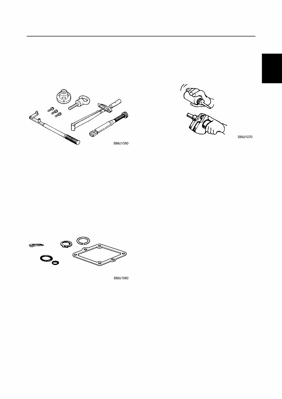
Special service tool
Use the recommended special service tools
to protect parts from damage. Use the right
tool in the right manner—do not improvise.
Tightening torque
Follow the tightening torque specifications
provided throughout the manual. When tight-
ening nuts, bolts, and screws, tighten the
large sizes first, and tighten fasteners starting
in the center and moving outward.
Non-reusable part
Always use new gaskets, seals, O-rings, cot-
ter pins, circlips, etc., when installing or
assembling parts.
Disassembly and assembly
1. Use compressed air to remove dust and
dirt during disassembly.
2. Apply engine oil to the contact surfaces
of moving parts before assembly.
3. Install bearings with the manufacture
identification mark in the direction indi-
cated in the installation procedure. In
addition, be sure to lubricate the bear-
ings liberally.
4. Apply a thin coat of water-resistant
grease to the lip and periphery of an oil
seal before installation.
5. Check that moving parts operate nor-
mally after assembly.
0-3 6BJ1K11
GEN
INFO
General information
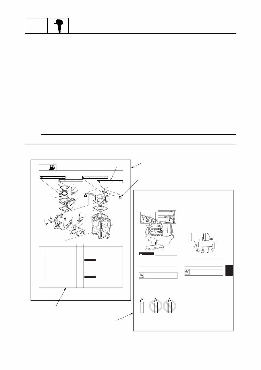
How to use this manual
Manual format
The format of this manual has been designed to make service procedures clear and easy to under-
stand. Use the information below as a guide for effective and quality service.
• Parts are shown and detailed in an exploded diagram and are listed in the component list (see a
in the figure below for an example page).
• The component list consists of part names and quantities, as well as bolt and screw dimensions
(see b in the figure below).
• Symbols are used to indicate important aspects of a procedure, such as the grade of lubricant and
lubrication point (see c in the figure below).
• Tightening torque specifications are provided in the exploded diagrams (see d in the figure below
for an example), and in the related detailed instructions. Some torque specifications are listed in
stages as torque figures or angles in degrees.
• Separate procedures and illustrations are used to explain the details of removal, checking, and
installation where necessary (see e in the figure below for an example page).
NOTE:
For troubleshooting procedures, see Chapter 4, “Troubleshooting.”
5-11 6AW3K11
FUEL
Fuel system
Throttle body
No. Part name Q’ty Remarks
1 Plastic tie 1
2 Joint 1
3 Nut 4
4 Washer 2
5 Electronic throttle valve assembly 1
6 Gasket 1 Not reusable
7 Bolt 1 M6 20 mm
8 Washer 1
9 Intake air pressure sensor 1
10 Bolt 4 M8 18 mm
11 Crip 1
12 Plate 1
13 Gasket 1 Not reusable
14 Bolt 3 M6 20 mm
15 Bolt 6 M8 35 mm
16 Surge tank 1
17 Clamp 1
1
2
3
4
6
7
8
9
10
10
11
12
13
14
15
16
17
18
19
20
21
22
23
24
25
26
5 13 N m (1.3 kgf m, 9.6 ft Ib) 13 N m (1.3 kgf m, 9.6 ft Ib) 13 N m (1.3 kgf m, 9.6 ft Ib) 5 N m (0.5 kgf m, 3.7 ft Ib)
LT
242
LT
242
S6AW05038
6AW3K11 5-30
Vapor separator
1
2
3
4
5
5
7
8
9
5. Drain the fuel from the vapor separator
drain hose by pressing the pressure
check valve using a thin screwdriver.
WARNING
Reduce the fuel pressure before loosen-
ing the vapor separator drain screw, or
pressurized fuel will spray out and may
result in serious injury.
6. Tighten the drain screw.
Checking the vapor separator
1. Reduce the fuel pressure. See Chapter
5, “Reducing the fuel pressure.”
2. Check the needle valve. Replace needle
valve assembly if bent or worn.
3. Check the float. Replace the float if there
is deterioration.
4. Check the high-pressure fuel pump filter.
Clean the filter if there is dirt or residue.
5. Install the needle valve and float to the
vapor separator cover.
6. Place the vapor separator cover assem-
bly in the position shown in the illustra-
tion, and then measure the float height
a.
NOTE:
To measure the height of the float, it should
be resting on the needle valve. Do not press
the float.
T R
. .
Vapor separator drain screw:
2 N·m (0.2 kgf·m, 1.5 ft·lb)
a
b
S6AW05023
S6AL4350
Float height a:
60.5±3.0 mm (2.38±0.12 in)
a
S6AW05024
a
b
c
d
e
You're Reading a Preview
What's Included?
 Lifetime Access
Fast Download Speeds
Online & Offline Access
Access PDF Contents & Bookmarks
Full Search Facility
Print one or all pages of your manual
$35.99
Yamaha outboard service manual F350 PID Range: 6AW-1000001~1006600 Mfg April 2005 ~ Dec 2011
Viewed 79 Times Today

What's Included?
Lifetime Access
Fast Download Speeds
Online & Offline Access
Access PDF Contents & Bookmarks
Full Search Facility
Print one or all pages of your manual
$35.99

Secure transaction
What's Included?
Lifetime Access
Fast Download Speeds
Online & Offline Access
Access PDF Contents & Bookmarks
Full Search Facility
Print one or all pages of your manual
Description
This manual is a comprehensive guide covering all Yamaha F350 PID Range: 6AW-1000001~1006600 manufactured from April 2005 to December 2011. It is a factory service manual that encompasses all aspects of the outboard motor. The procedures in this manual are presented in a sequential, step-by-step format, providing mechanics with an easily accessible reference. It includes detailed explanations of disassembly, repair, assembly, and inspection operations. Each chapter is accompanied by exploded diagrams before the disassembly section, facilitating the identification of the correct procedures for disassembly and assembly.


