I GEN ?l CHAPTER 1 GENERAL INFORMATION OUTBOARD MOTOR IDENTIFICATION .......................... 1-1 MODEL AND SERIALNUMBER ................................ 1-1 ENGINE SERIAL NUMBER .................................... 1-1 TECHNICAL FEATURES ........................................ 1-2 ELECTRICAL ................................................. 1-2 OIL INJECTION SYSTEM ..................................... 1-6
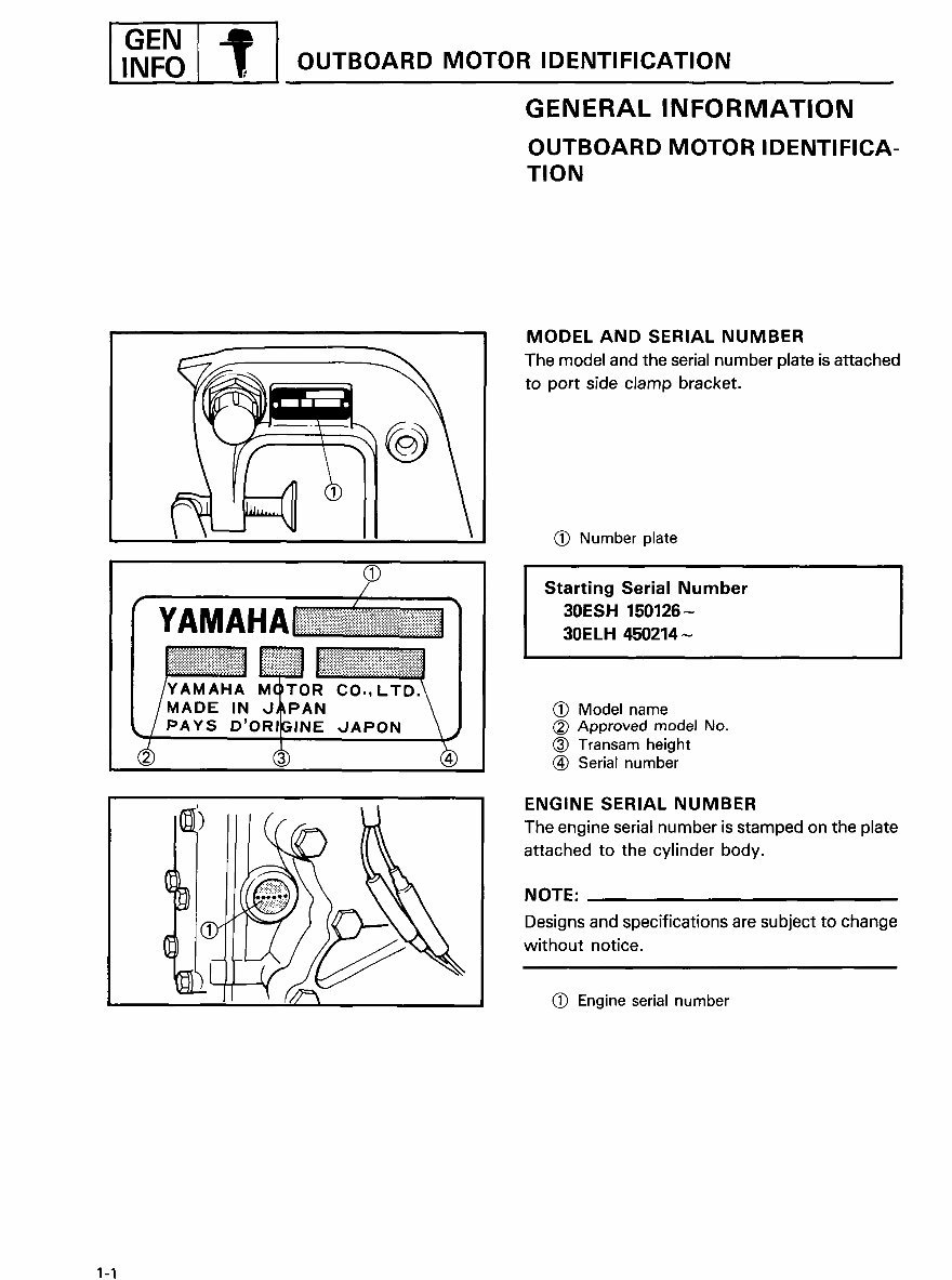
INFO OUTBOARD MOTOR IDENTIFICATION GENERAL INFORMATION OUTBOARD MOTOR IDENTIFICA- TION MODEL AND SERIAL NUMBER Themodeland the serial number plate is attached to port side clamp bracket. (_) Number plate (9 / Starting Serial Number · [.............. _ "] 30ESH 150126- YAMAHA iiiiiJ_"_J!?_?_?_J:i_ii_?j?_i'i:.?_iii_q 3DE LH 450214 _ :_:_ !!iiiiiiiiiiiiiiiiiiiiiiiiiiiiii_iiii !iI I /Y^M^.^M,,TO. CO.,LTD.\ I /MADE IN J_PAN _ ! (_) Model name ,_/ PAYS D'ORIGINE ,./APON \ J (_) Approved model No. (_) Transam height (_ _ (_ Serial number ENGINE SERIAL NUMBER '_'[_.') The engine serial number is stamped on the plate attached to the cylinder body. _:_) NOTE: Designs and specifications are subject tochange _}[_ without notice. Q Engine serial number 1-1
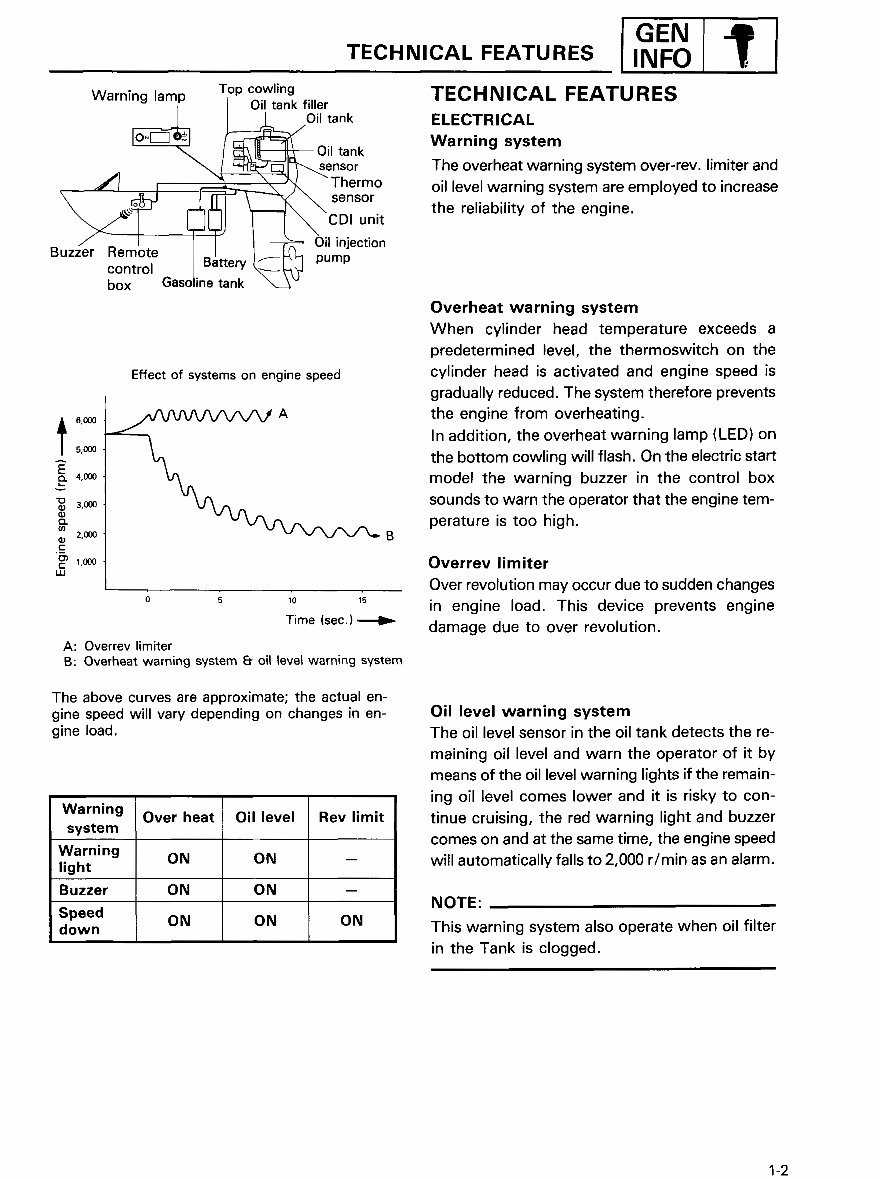
I GEN TECHNICAL FEATURES I ,.ol? I l . Top cowling TECHNICAL FEATURES Warning lam? I Oil tank filler O'I-- _ _Oil tank ELECTRICAL / __ Oil tank Warning system _/ _. l_.l /"'"-_ ens°r The overheat warning system over-rev, limiter and J_ . _ ',, ]V, ' Thermo _ __ sensor oil levelwarning system areemployed to increase "_-"_-_ [_[_1 _-_CDI unit the reliability of the engine. I I I ___ Oil injection Buzzer RemoteIaa'.e IrFh pump control 1_Dazzery L_t_ j ,-- box Gasoline tank '_.__ 'J Overheat warning system When cylinder head temperature exceeds a predetermined level, thethermoswitch on the Effect of systems on engine speed cylinder head is activated and engine speed is gradually reduced. The system therefore prevents 6,_ _A the engine from overheating. t In addition, the overheatwarning lamp (LED) on A s,_0_ the bottom cowling will flash. On the electric start E 4,0_ model the warning buzzer in the control box 3,_ sounds to warn the operator that the engine tem- perature istoohigh. 2,0m B t-- c _ _.0_ Overrev limiter UJ Over revolution may occur due to sudden changes o s ,0 ,s in engine load. This device prevents engine Time (sec.)_ damage due to over revolution. A: Overrev limiter B: Overheat warningsystem_ oil _eve[ warningsystem The above curves are approximate; the actual en- gine speed will vary depending on changes in en- Oillevel warning system gine load. The oil level sensor in the oil tank detects the re- maining oil level and warn the operator of it by means of the oil level warning lights if the remain- lng oil level comes lower and it is risky to con- Warning Over heat Oil level Rev limit tinue cruising, the red warning light and buzzer system comes on and at the same time, the engine speed Warning ON ON -- will automatically falls to 2,000 r/min as an alarm. light Buzzer ON ON -- NOTE: Speed ON ON ON down Thiswarning system alsooperate when oil filter intheTank is clogged. 1-2
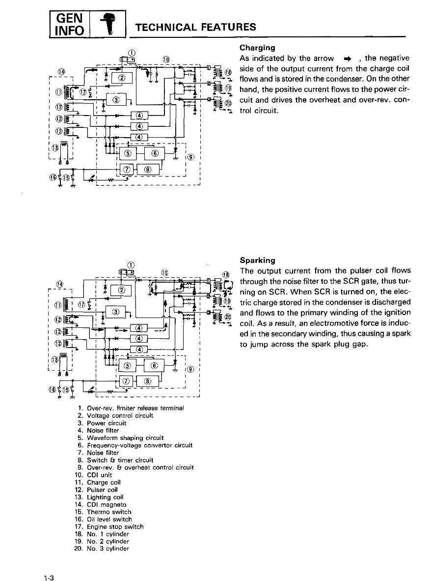
JGEN Charging _-i- [_. T_ _ AS indicated by the arrow _ , the negative ___! _-i_ side of the output current from the charge coil r-- -qq I I "__ I ]_'[ [-- flows and isstored in the condenser. On the other I_ / I, hand. the positive current flowstothe power cir- cuit and drives the overheat and over-rev, con- @ll_--_-----_: J_l __. I'lr-_-_ 1_ trolcircuit. @11 - ';_ ,® ' ' L ................. (_ Sparking .____1:___. ____ _----_ -- =---_ _ _ The output current from the pulser coil flows r--_- -_ I J_I_ r- _I --_ i _dr_lJ._ through the noise filter to the SCR gate, thus tur- , .-,--J , ' , '/ "", J- _ "r.' _ ningonSCR. When SCR is turned on, theelec- i@ tric chargestored in the condenser is discharged ,.11_----I ',._l_ I*_ ;,_11_ and flows to the primary winding of the ignition ,, ed in the secondarywinding, thus causinga spark 'l to jump acrossthe sparkplug gap. , =, ,, ........... ;__. tt :! , I Im I _ (5) t--I (6)_ '_ L_ .___._ , ,_ _ , t__.7_._,J _ ,_ e _ I I I-'-_---i _ I I _.J,_,,_ i ,, L"JL_q_...___. r': .... · ,_,,_, _.._%__. ..... _'-_-____ 1. Over-rev. limiter release terminal 2. Voltage control circuit 3. Power circuit 4. Noise filter 5. Waveform shaping circuit 6. Frequency-voltageconvertor circuit 7. Noise filter 8. Switch 8- timer circuit 9. Over-rev. 8- overheat control circuit 10. CDI unit 11. Charge coil 12. Pulser coil 13. Lighting coil 14. CDI magneto 15. Thermo switch 16. Oil level switch 17. Engine stop switch 18. No. 1 cylinder 19. No. 2 cylinder 20. No. 3 cylinder 1-3
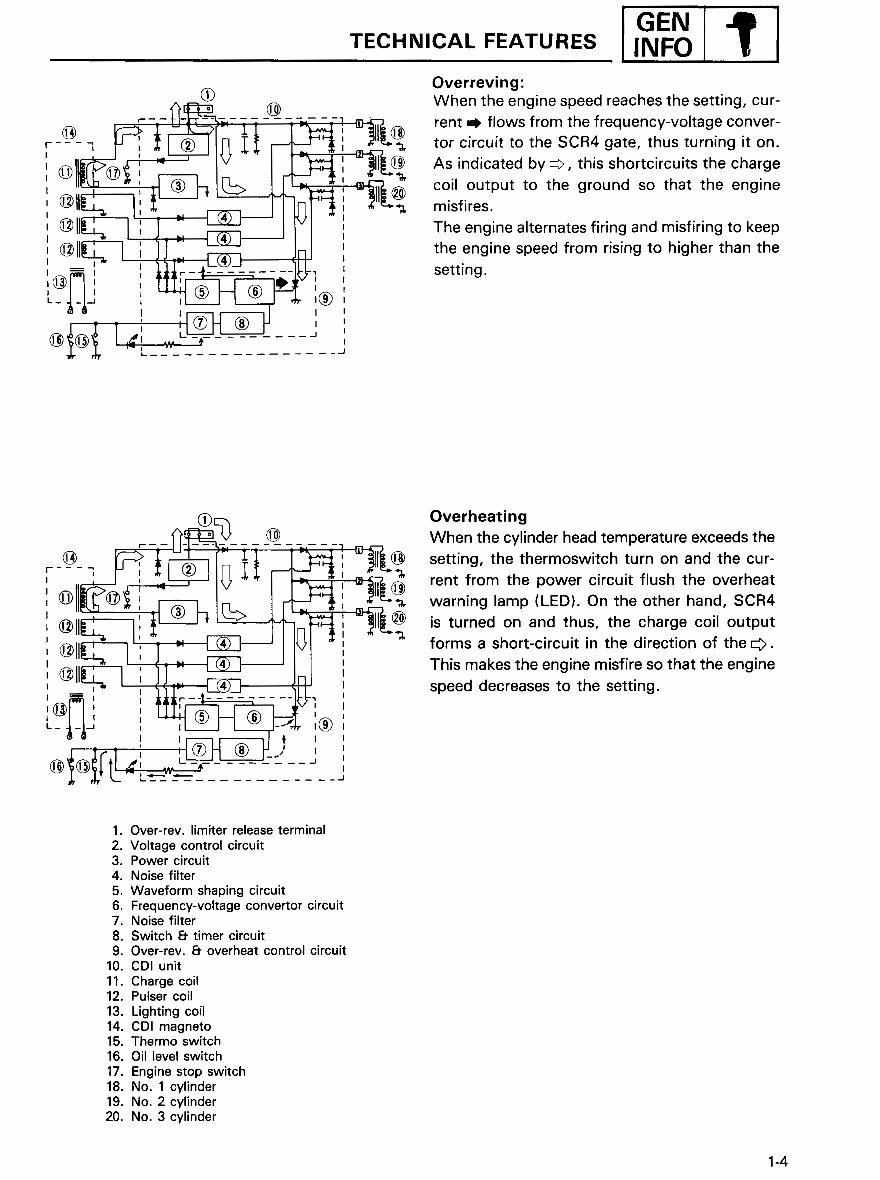
I GEN ICAL FEATURES [ TECHN _ INFOI '_, I Overreving: Q When the engine speed reaches the setting, cur- .__ fi____=_ _e --- rent m flows from the frequency-voltage conver- -- [- _ _, - - _, tor circuit to the SCR4 gate, thus turning it on. I]_i _'[---_--L/ / _ ! _e_ As indicated by _, this shortcircuits the charge '_11 %> _ coil output to the ground so that the engine DII[ . ¢11 _ ¢ ] misfires. !, r_--I-- The engine alternates firing and misfiring to keep @11_ _i_ ,,m_-] :__n setting.the engine speed from rising to higher than the '-_-_ mi _ I I _ I _, I(_) ' I e_,,_ · _-.___'_z_l_'_'_'_'--- ...... Over.ea.,n. ............ When the cylinder head temperature exceeds the --_-] _,__ IR _J_ __'_ setting, the thermoswitch turn on and thecur- @l_--__ i _ _11_ rent fromthe power circuit flush the overheat warning lamp (LED). On the other hand, SCR4 (_ll_'__'_, m_-_ is turned on and thus, the charge coil output ell forms a short-circuit in the direction of theO. ell____---l'.; i)_J=_ 'F-_ ! This makestheenginemisfiresothattheengine [-_!-'---_'' _,F__-i_----L_-4-_--_f_ I ' speed decreases to the setting. (_)= I I r ........... I I e_ ! Ii--_-l_l f I I 1. Over-rev. limiter release terminal 2. Voltage control circuit 3. Power circuit 4. Noise filter 5. Waveform shaping circuit 6. Frequency-voltage convertor circuit 7. Noise filter 8. Switch 6t timer circuit 9. Over-rev, 8' overheat control circuit 10. CDI unit 11. Charge coil 12. Pulser coil 13. Lighting coil 14. CDI magneto 15. Thermo switch 16. Oil level switch 17. Engine stop switch 18. No. 1 cylinder 19. No. 2 cylinder 20. No. 3 cylinder 1-4
This manual is a comprehensive guide for repairing and maintaining a Yamaha Outboard 1992 30 hp 2 cyl. (496cc) 2-stroke engine. It covers a wide range of topics, from basic maintenance tasks to more complex repairs such as transmission swaps. The manual includes detailed illustrations and easy-to-understand instructions, making it suitable for both professional mechanics and DIY enthusiasts.
With the search function, you can easily navigate through the manual and print specific pages as needed. Whether you're looking to perform routine maintenance or tackle a more challenging repair, this Factory Service Repair Manual provides step-by-step guidance. It equips owners with the knowledge to make informed decisions about their engine's upkeep and repairs.
For those seeking a reliable service manual, this resource ensures high-quality content and is backed by excellent customer service. Visit www.johnsmanuals.com for additional service manuals.

 2-stroke Service/Shop Repair Manual")