Contents General information 1 GEN INFO Specifications 2 SPEC Periodic checks and adjustments 3 CHK ADJ Fuel system 4 FUEL Power unit 5 POWR Lower unit 6 LOWR Bracket unit 7 BRKT Electrical systems 8 ELEC Troubleshooting 9 TRBL SHTG Index – +
GEN INFO 60V1E11 General information How to use this manual ................................................................................. 1-1 Manual format............................................................................................ 1-1 Symbols ..................................................................................................... 1-2 Safety while working...................................................................................... 1-3 Fire prevention........................................................................................... 1-3 Ventilation .................................................................................................. 1-3 Self-protection ........................................................................................... 1-3 Parts, lubricants, and sealants .................................................................. 1-3 Good working practices ............................................................................. 1-4 Disassembly and assembly ....................................................................... 1-4 Identification ................................................................................................... 1-5 Applicable models ..................................................................................... 1-5 Serial number ............................................................................................ 1-5 Features and benefits .................................................................................... 1-6 Cylinder body and cylinder head ............................................................... 1-6 Pistons and connecting rods ..................................................................... 1-7 Fuel injection pumps.................................................................................. 1-8 Flywheel magnet ....................................................................................... 1-9 ECM (Electronic Control Module) ............................................................ 1-10 Injector drivers ......................................................................................... 1-12 Idle silencer ............................................................................................. 1-13 Power unit mounting bolts ....................................................................... 1-14 Cooling water inlet ................................................................................... 1-15 Transmission components....................................................................... 1-16 Technical tips ............................................................................................... 1-17 Electronic control system......................................................................... 1-17 Partial cylinder operation ......................................................................... 1-18 Fail-safe control ....................................................................................... 1-19 Warning control ....................................................................................... 1-20 Over-revolution control ............................................................................ 1-20 Shift cut control ........................................................................................ 1-20 Propeller selection ....................................................................................... 1-21 Propeller size ........................................................................................... 1-21 Selection .................................................................................................. 1-21
60V1E11 1 2 3 4 5 6 7 8 9 Predelivery checks ...................................................................................... 1-22 Checking the fuel system ........................................................................ 1-22 Checking the gear oil level ...................................................................... 1-22 Checking the engine oil level ................................................................... 1-22 Checking the battery................................................................................ 1-23 Checking the outboard motor mounting height ........................................ 1-23 Checking the remote control cables ........................................................ 1-23 Checking the steering system ................................................................. 1-24 Checking the gear shift and throttle operation ......................................... 1-24 Checking the power trim and tilt system .................................................. 1-24 Checking the engine start switch and engine shut-off switch .................. 1-24 Checking the cooling water pilot hole ...................................................... 1-25 Test run ................................................................................................... 1-25 Break-in ................................................................................................... 1-25 After test run ............................................................................................ 1-25
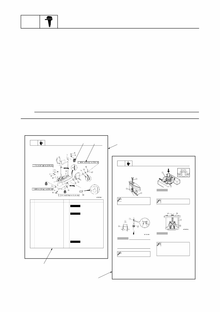
GEN INFO General information 1-1 60V1E11 How to use this manual 1 Manual format The format of this manual has been designed to make service procedures clear and easy to under- stand. Use the information below as a guide for effective and quality service. 1 Parts are shown and detailed in an exploded diagram and are listed in the components list. 2 Tightening torque specifications are provided in the exploded diagrams and after a numbered step with tightening instructions. 3 Symbols are used to indicate important aspects of a procedure, such as the grade of lubricant and lubrication point. 4 The components list consist of part names and part quantities, as well as bolt and screw dimen- sions. 5 Service points regarding removal, checking, and installation are shown in individual illustrations to explain the relevant procedure. NOTE: For troubleshooting procedures, see Chapter 9, “Troubleshooting.” LOWR Lower unit 6-5 62Y5A11 Lower unit No. Part name Q’ty Remarks 1 Lower unit 1 2 Plastic tie 1 Not reusable 3 Hose 1 4 Check screw 1 5 Gasket 2 Not reusable 6 Dowel pin 2 7 Bolt 4 M10 40 mm 8 Drain screw 1 9 Grommet 1 10 Bolt 1 M10 45 mm 11 Bolt 1 M8 60 mm 12 Thrust washer 1 13 Propeller 1 14 Washer 1 15 Washer 1 16 Cotter pin 1 Not reusable 17 Propeller nut 1 18 Trim tab 1 LOWR Lower unit 6-19 62Y5A11 Removing the drive shaft 1. Remove the drive shaft assembly and pinion, and then pull out the forward gear. Disassembling the drive shaft 1. Install the pinion nut 1, tighten it finger tight, and then remove the drive shaft bearing 2 using a press. CAUTION: • Do not press the drive shaft threads a directly. • Do not reuse the bearing, always replace it with a new one. Disassembling the forward gear 1. Remove the taper roller bearing from the forward gear using a press. CAUTION: Do not reuse the bearing, always replace it with a new one. 2. Remove the needle bearing from the for- ward gear. CAUTION: Do not reuse the bearing, always replace it with a new one. Drive shaft holder 4 1: 90890-06518 Pinion nut holder 2: 90890-06505 Socket adapter 2 3: 90890-06507 Bearing inner race attachment 3: 90890-06639 S62Y6850K Bearing separator 1: 90890-06534 Stopper guide plate 2: 90890-06501 Stopper guide stand 3: 90890-06538 Bearing puller 4: 90890-06535 Bearing puller claw 1 5: 90890-06536 S62Y6740K 5 4 3 2 1
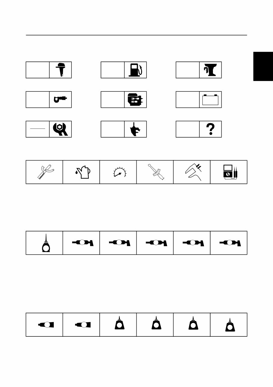
60V1E11 1-2 1 2 3 4 5 6 7 8 9 Symbols The symbols below are designed to indicate the content of a chapter. General information Specifications Periodic checks and adjustments Fuel system Power unit Lower unit Bracket unit Electrical systems Troubleshooting GEN INFO SPEC CHK ADJ FUEL POWR LOWR BRKT ELEC TRBL SHTG – + Symbols 1 to 6 indicate specific data. 1 Special tool 2 Specified oil or fluid 3 Specified engine speed 4 Specified tightening torque 5 Specified measurement 6 Specified electrical value (resistance, voltage, electric current) Symbols 7 to B in an exploded diagram indicate the grade of lubricant and the lubrication point. 7 Apply 2-stroke outboard motor oil 8 Apply water resistant grease (Yamaha grease A) 9 Apply molybdenum disulfide grease 0 Apply corrosion resistant grease (Yamaha grease D) A Apply low temperature resistant grease (Yamaha grease C) B Apply injector grease Symbols C to H in an exploded diagram indicate the type of sealant or locking agent and the appli- cation point. C Apply Gasket Maker D Apply Yamabond No. 4 E Apply LOCTITE 271 (red) F Apply LOCTITE 242 (blue) G Apply LOCTITE 572 H Apply silicon sealant 1 2 3 4 5 6 T R . . 7 8 9 0 A B E A M D C I C D E F G H GM 4 271 LT 242 LT 572 LT SS How to use this manual
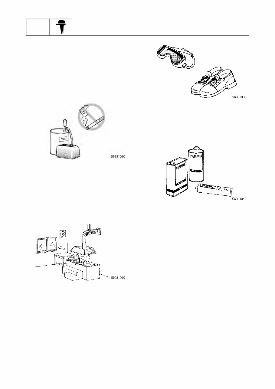
GEN INFO General information 1-3 60V1E11 Safety while working 1 To prevent an accident or injury and to ensure quality service, follow the safety pro- cedures provided below. Fire prevention Gasoline is highly flammable. Keep gasoline and all flammable products away from heat, sparks, and open flames. Ventilation Gasoline vapor and exhaust gas are heavier than air and extremely poisonous. If inhaled in large quantities they may cause loss of consciousness and death within a short time. When test running an engine indoors (e.g., in a water tank) be sure to do so where ade- quate ventilation can be maintained. Self-protection Protect your eyes by wearing safety glasses or safety goggles during all operations involv- ing drilling and grinding, or when using an air compressor. Protect your hands and feet by wearing pro- tective gloves and safety shoes when neces- sary. Parts, lubricants, and sealants Use only genuine Yamaha parts, lubricants, and sealants or those recommended by Yamaha, when servicing or repairing the out- board motor. Under normal conditions, the lubricants men- tioned in this manual should not harm or be hazardous to your skin. However, you should follow these precautions to minimize any risk when working with lubricants. 1. Maintain good standards of personal and industrial hygiene. 2. Change and wash clothing as soon as possible if soiled with lubricants. 3. Avoid contact with skin. Do not, for example, place a soiled rag in your pocket. 4. Wash hands and any other part of the body thoroughly with soap and hot water after contact with a lubricant or lubricant soiled clothing has been made. 5. To protect your skin, apply a protective cream to your hands before working on the outboard motor.
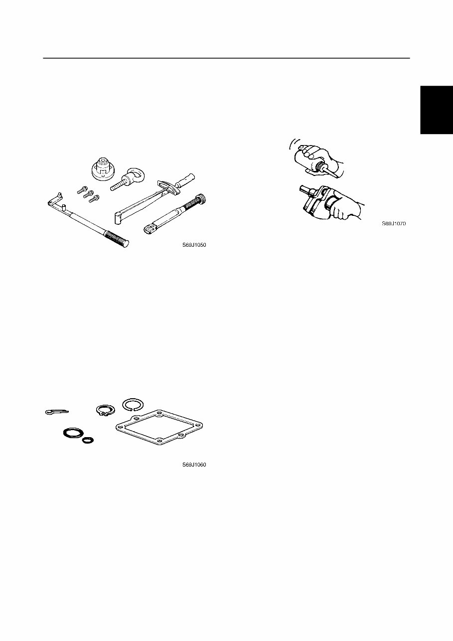
60V1E11 1-4 1 2 3 4 5 6 7 8 9 6. Keep a supply of clean, lint-free cloths for wiping up spills, etc. Good working practices Special service tools Use the recommended special service tools to protect parts from damage. Use the right tool in the right manner—do not improvise. Tightening torques Follow the tightening torque specifications provided throughout the manual. When tight- ening nuts, bolts, and screws, tighten the large sizes first, and tighten fasteners starting in the center and moving outward. Non-reusable parts Always use new gaskets, seals, O-rings, cot- ter pins, circlips, etc., when installing or assembling parts. Disassembly and assembly 1. Use compressed air to remove dust and dirt during disassembly. 2. Apply engine oil to the contact surfaces of moving parts before assembly. 3. Install bearings with the manufacture identification mark in the direction indi- cated in the installation procedure. In addition, be sure to lubricate the bearings liberally. 4. Apply a thin coat of water-resistant grease to the lip and periphery of an oil seal before installation. 5. Check that moving parts operate nor- mally after assembly. Safety while working
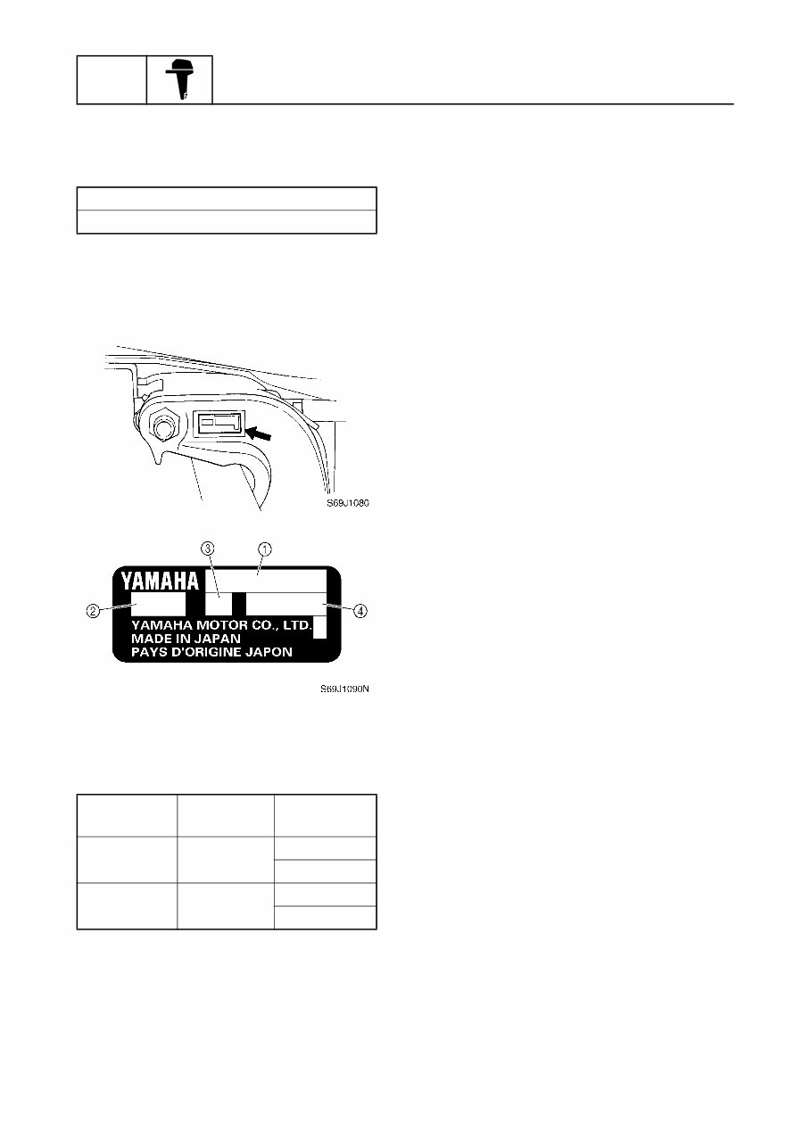
GEN INFO General information 1-5 60V1E11 Identification 1 Applicable models This manual covers the following models. Serial number The outboard motor serial number is stamped on a label attached to the port clamp bracket. 1 Model name 2 Approved model code 3 Transom height 4 Serial number Applicable models Z250TR, LZ250TR Model name Approved model code Starting serial No. Z250TR 60V X: 1000001– U: 1000001– LZ250TR 60W X: 1000001– U: 1000001–
You're Reading a Preview
What's Included?
Lifetime Access
Fast Download Speeds
Online & Offline Access
Access PDF Contents & Bookmarks
Full Search Facility
Print one or all pages of your manual
$39.99
2004 YAMAHA VZ300 2-STROKE OUTBOARD Factory Service & Work Shop Manual
Upon purchasing this manual, you will receive a .PDF file containing an email contact. After contacting us, you will receive a reply with a link to access the manual for your 2004 YAMAHA VZ300 2-STROKE OUTBOARD.
This comprehensive manual covers every aspect of your machine, providing detailed guidance on every nut and bolt. With hundreds of pages, it offers solutions for various issues, from simple tasks like an oil change to more complex procedures like a transmission swap. The manual includes numerous illustrations to assist you and features easy-to-understand text throughout.
Utilize the search function to navigate the manual efficiently and print the necessary pages as needed. This Factory Service Repair Manual is designed to walk you through the fundamentals of maintenance and repair, providing step-by-step instructions to equip you with the knowledge mastered by factory-trained technicians.
By leveraging the insights offered in this service repair manual, any owner can confidently make informed decisions regarding the maintenance and repair of their machine.
Rest assured, in addition to the high-quality service manual, we are committed to delivering excellent customer service, ensuring your satisfaction with your purchase.
Reviews
Q&A
Recently Viewed
5,521,897Happy Clients
2,594,462eManuals
1,120,453Trusted Sellers
15Years in Business
Price:
Actual Price:
2004 YAMAHA VZ300 2-STROKE OUTBOARD Factory Service & Work Shop Manual







 Lifetime Access




