E HOW TO USE THIS MANUAL MANUAL FORMAT All of the procedures in this manual are organized in a sequential, step-by-step format. The information has been compiled to provide the mechanic with an easy to read, handy refer- ence that contains comprehensive explanations of all disassembly, repair, assembly, and inspection operations. In this revised format, the condition of a faulty component will precede an arrow symbol and the course of action required will follow the symbol, e.g., ● Bearings Pitting/scratches → Replace. To assist you in finding your way through this manual, the section title and major heading is given at the top of every page. ILLUSTRATIONS The illustrations within this service manual represent all of the designated models. CROSS REFERENCES The cross references have been kept to a minimum. Cross references will direct you to the appropriate section or chapter.
E IMPORTANT INFORMATION In this Service Manual particularly important information is distinguished in the following ways. The Safety Alert Symbol means ATTENTION! BECOME ALERT! YOUR SAFETY IS INVOLVED! WARNING Failure to follow WARNING instructions could result in severe injury or death to the machine operator, a bystander, or a person inspecting or repairing the outboard motor. CAUTION: A CAUTION indicates special precautions that must be taken to avoid damage to the out- board motor. NOTE: A NOTE provides key information to make procedures easier or clearer.
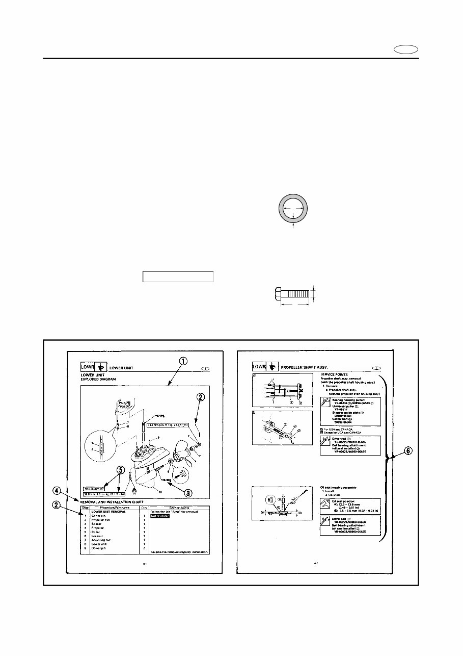
E HOW TO USE THIS MANUAL 1 To help identify parts and clarify procedure steps, there are exploded diagrams at the start of each removal and disassembly section. 2 Numbers are given in the order of the jobs in the exploded diagram. A circled number indicates a disassembly step. 3 Symbols indicate parts to be lubricated or replaced (see “SYMBOLS”). 4 A job instruction chart accompanies the exploded diagram, providing the order of jobs, names of parts, notes in jobs, etc. Example: O-ring size 39.5 × 2.5 mm: Inside diameter (D) × Ring diameter (d) 5 Dimension figures and the number of parts, are provided for fasteners that require a tight- ening torque. Example: Bolt or screw size : M10 (D) × 25 mm (L) (2 pieces) 6 Jobs requiring more information (such as special tools and technical data) are described sequentially. d D 10 × 25 mm (2) D L
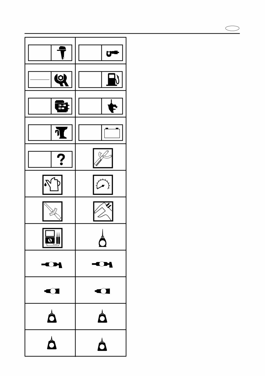
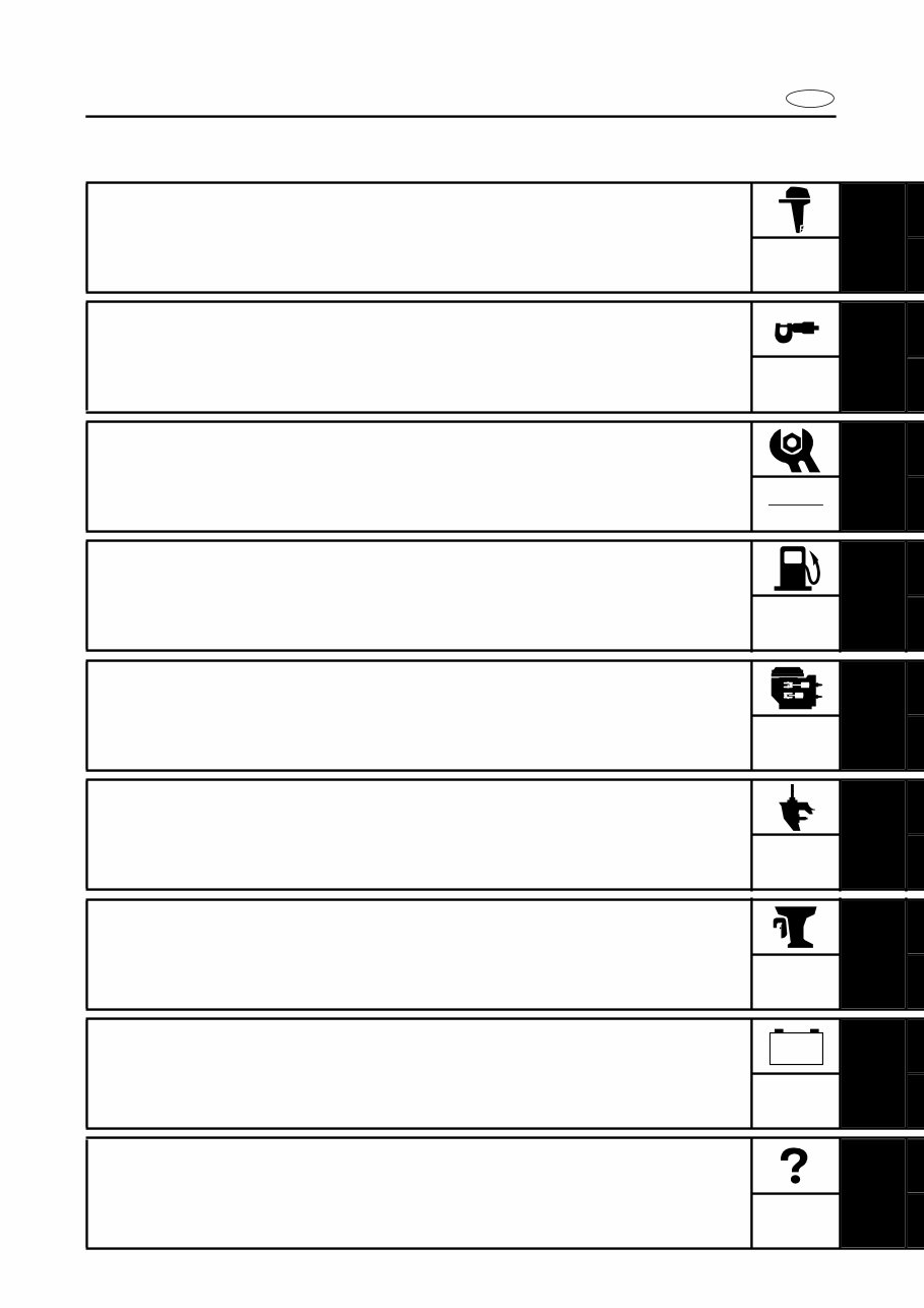
E A50001-1-4 SYMBOLS Symbols 1 to 9 are designed as thumb- tabs to indicate the content of a chapter. 1 General information 2 Specifications 3 Periodic inspection and adjustment 4 Fuel system 5 Power unit 6 Lower unit 7 Bracket unit 8 Electrical systems 9 Trouble-analysis Symbols 0 to E indicate specific data: 0 Special tool A Specified liquid B Specified engine speed C Specified torque D Specified measurement E Specified electrical value [Resistance (Ω), Voltage (V), Electric current (A)] Symbol F to H in an exploded diagram indicate the grade of lubricant and the loca- tion of the lubrication point: F Apply Yamaha 4-stroke outboard motor oil G Apply water resistant grease (Yamaha grease A, Yamaha marine grease) H Apply molybdenum disulfide oil Symbols I to N in an exploded diagram indicate the grade of the sealing or locking agent and the location of the application point: I Apply Gasket Maker ® J Apply Yamabond #4 (Yamaha bond number 4) K Apply LOCTITE ® No. 271 (Red LOCTITE) L Apply LOCTITE ® No. 242 (Blue LOCTITE) M Apply LOCTITE ® No. 572 N Apply silicon sealant 1 2 3 4 5 6 7 8 9 0 A B C D E F G H I J K L M N GEN INFO SPEC INSP ADJ FUEL POWR LOWR BRKT – + ELEC TRBL ANLS T R . . E A M GM 4 271 LT 242 LT 572 LT SS
E INDEX GENERAL INFORMATION 1 SPECIFICATIONS 2 SPEC PERIODIC INSPECTION AND ADJUSTMENT 3 FUEL SYSTEM 4 FUEL POWER UNIT 5 POWR LOWER UNIT 6 LOWR BRACKET UNIT 7 BRKT ELECTRICAL SYSTEM 8 ELEC TROUBLE-ANALYSIS 9 GEN INFO INSP ADJ – + TRBL ANLS A30000-0
E 1 2 3 4 5 6 7 8 9 GEN INFO CHAPTER 1 GENERAL INFORMATION IDENTIFICATION.............................................................................................1-1 SERIAL NUMBER .....................................................................................1-1 STARTING SERIAL NUMBERS ...............................................................1-1 SAFETY WHILE WORKING ............................................................................1-2 FIRE PREVENTION ...................................................................................1-2 VENTILATION ...........................................................................................1-2 SELF-PROTECTION ..................................................................................1-2 OILS, GREASES AND SEALING FLUIDS ................................................1-2 GOOD WORKING PRACTICES ................................................................1-3 DISASSEMBLY AND ASSEMBLY ...........................................................1-4 SPECIAL TOOLS .............................................................................................1-5 MEASURING ............................................................................................1-5 REMOVAL AND INSTALLATION.............................................................1-7
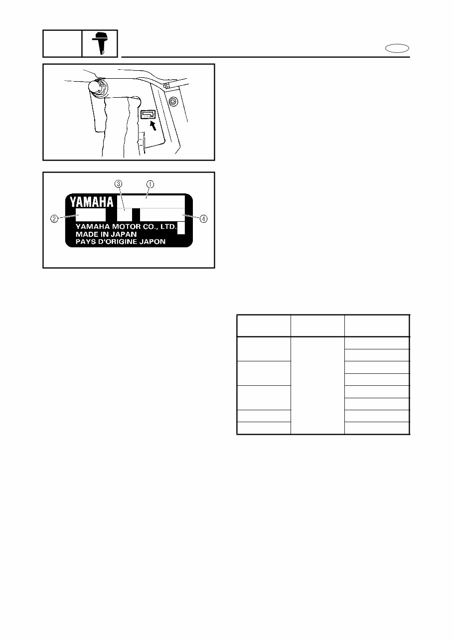
1-1 GEN INFO E IDENTIFICATION A60000-1* IDENTIFICATION SERIAL NUMBER The outboard motor serial number is stamped on a label attached to the port clamp bracket. 1 Model name 2 Approved model code 3 Transom height 4 Serial number STARTING SERIAL NUMBERS The starting serial number blocks are as fol- lows: Model name Approval model code Starting serial No. F25MH 65W S: 1008911 ~ L: 1008911 ~ F25EH S: 1008911 ~ L: 1008911 ~ F25ER S: 1008911 ~ L: 1008911 ~ F25TR L: 1008911 ~ T25TR L: 1008911 ~
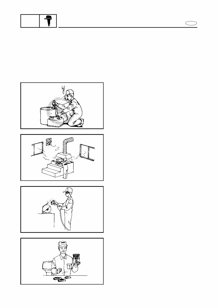
1-2 GEN INFO E SAFETY WHILE WORKING SAFETY WHILE WORKING The procedures given in this manual are those recommended by Yamaha to be fol- lowed by Yamaha dealers and their mechanics. FIRE PREVENTION Gasoline (petrol) is highly flammable. Petroleum vapor is explosive if ignited. Do not smoke while handling gasoline and keep it away from heat, sparks and open flames. VENTILATION Petroleum vapor is heavier than air and is deadly if inhaled in large quantities. Engine exhaust gases are harmful to breathe. When test-running an engine indoors, maintain good ventilation. SELF-PROTECTION Protect your eyes with suitable safety glasses or safety goggles, when grinding or when doing any operation which may cause particles to fly off. Protect hands and feet by wearing safety gloves or protective shoes if appropriate to the work you are doing. OILS, GREASES AND SEALING FLUIDS Use only genuine Yamaha oils, greases and sealing fluids or those recommended by Yamaha.
Get the comprehensive repair manual for the 2006 Yamaha 25 HP (F25C/T25C) Outboard. This manual equips you with all the necessary troubleshooting and replacement procedures recommended by the manufacturer. It includes step-by-step instructions, clear images, and exploded-view illustrations, making it an essential tool for both professional mechanics and DIY enthusiasts.
Regular maintenance is crucial for your outboard's longevity, and this manual provides the manufacturer's recommended troubleshooting charts and replacement procedures. It's your go-to resource for keeping your outboard in top condition and ensuring minimal downtime. With this manual, you can save on repairs, enhance your outboard's reliability, and prevent potential issues.
Please note:
This is not a generic repair manual; it is the official manual used by professional technicians for servicing and maintaining your outboard.
No more flipping through numerous pages or dealing with greasy, torn, or lost pages. This digital manual offers convenient search, screenshot, and bookmark functions, providing a superior alternative to traditional bound manuals.
It is printable, available in English, and compatible with various electronic devices, including PC, Mac computers, Android and Apple smartphones, and tablets. Adobe Reader (free) is the only requirement for accessing the manual.
Recently Viewed
5,521,897Happy Clients
2,594,462eManuals
1,120,453Trusted Sellers
15Years in Business
Price:
Actual Price:
2006 Yamaha 25 HP (F25C/T25C) Outboard OEM Service & Repair Manual