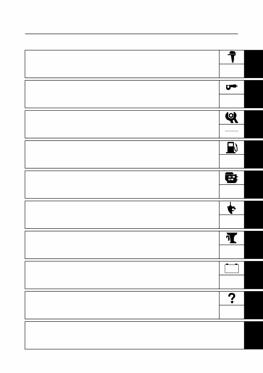
Contents General information 1 GEN INFO Specification 2 SPEC Periodic check and adjustment 3 CHK ADJ Fuel system 4 FUEL Power unit 5 POWR Lower unit 6 LOWR Bracket unit 7 BRKT Electrical system 8 ELEC Troubleshooting 9 TRBL SHTG Index – +
GEN INFO 6P21H11 General information How to use this manual ................................................................................. 1-1 Manual format............................................................................................ 1-1 Symbol ....................................................................................................... 1-2 Abbreviation............................................................................................... 1-3 Safety while working...................................................................................... 1-4 Fire prevention........................................................................................... 1-4 Ventilation .................................................................................................. 1-4 Self-protection ........................................................................................... 1-4 Part, lubricant, and sealant ........................................................................ 1-4 Good working practice ............................................................................... 1-5 Disassembly and assembly ....................................................................... 1-5 Identification ................................................................................................... 1-6 Model ......................................................................................................... 1-6 Serial number ............................................................................................ 1-6 Special service tool ....................................................................................... 1-7 Feature and benefit ...................................................................................... 1-13 ECM system ............................................................................................ 1-13 Electronic fuel injection control system.................................................... 1-25 Ignition timing control system .................................................................. 1-29 Knock control system .............................................................................. 1-32 Variable camshaft timing control system ................................................. 1-35 Electronic throttle valve control system ................................................... 1-40 Engine speed control system .................................................................. 1-43 Lower unit ................................................................................................ 1-47 Propeller selection ....................................................................................... 1-48 Propeller size ........................................................................................... 1-48 Selection .................................................................................................. 1-48
6P21H11 1 2 3 4 5 6 7 8 9 Predelivery check ........................................................................................ 1-49 Checking the fuel system ........................................................................ 1-49 Checking the engine oil level ................................................................... 1-49 Checking the gear oil level ...................................................................... 1-49 Checking the battery................................................................................ 1-49 Checking the outboard motor mounting height ........................................ 1-50 Checking the remote control cable .......................................................... 1-50 Checking the steering system ................................................................. 1-51 Checking the gear shift and throttle operation ......................................... 1-51 Checking the PTT system ....................................................................... 1-51 Checking the engine start switch and engine stop lanyard switch .......... 1-51 Checking the cooling water pilot hole ...................................................... 1-52 Test run ................................................................................................... 1-52 Break-in ................................................................................................... 1-52 After test run ............................................................................................ 1-52
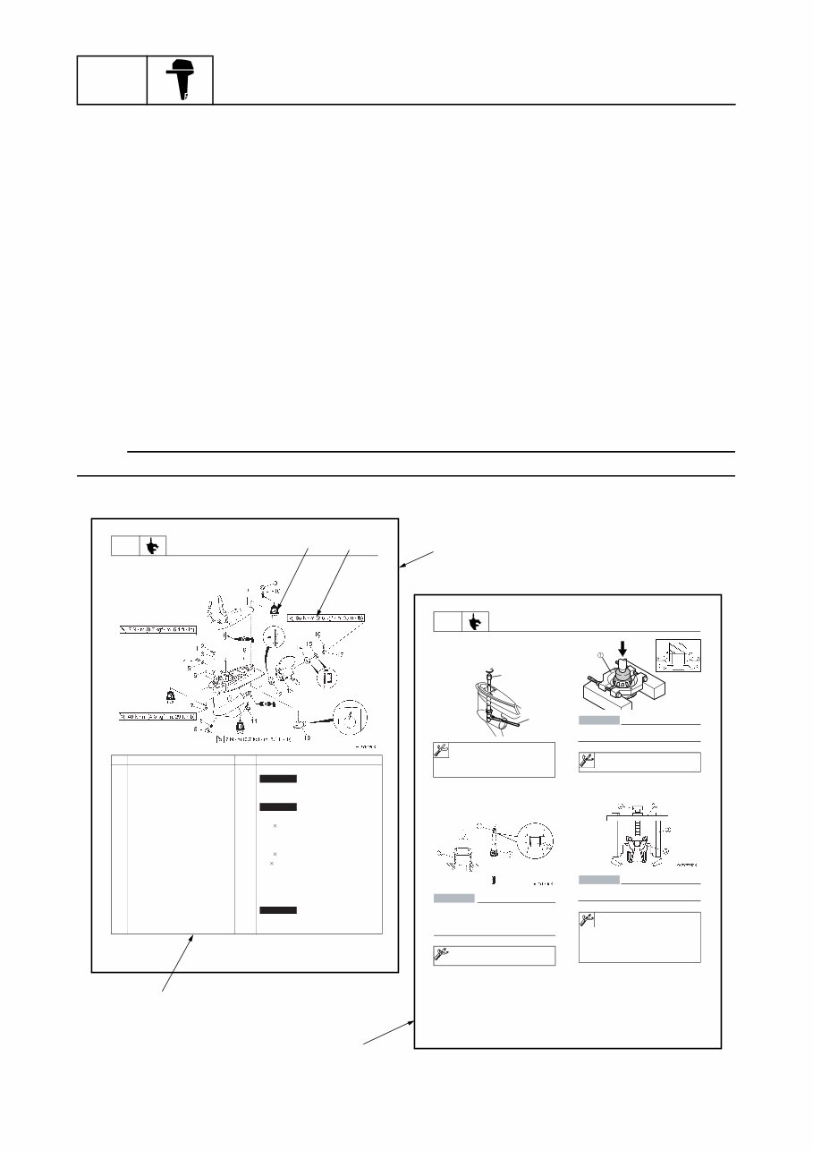
GEN INFO General information 1-1 6P21H11 How to use this manual 1 Manual format The format of this manual has been designed to make service procedures clear and easy to under- stand. Use the information below as a guide for effective and quality service. • Parts are shown and detailed in an exploded diagram and are listed in the component list (see 1 in the figure below for an example page). • The component list consists of part names and quantities, as well as bolt and screw dimensions (see 2 in the figure below). • Symbols are used to indicate important aspects of a procedure, such as the grade of lubricant and lubrication point (see 3 in the figure below). • Tightening torque specifications are provided in the exploded diagrams (see 4 in the figure below for an example), and in the related detailed instructions. Some torque specifications are listed in stages as torque figures or angles in degrees. • Separate procedures and illustrations are used to explain the details of removal, checking, and installation where necessary (see 5 in the figure below for an example page). NOTE: For troubleshooting procedures, see Chapter 9, “Troubleshooting.” LOWR Lower unit 6-5 62Y5A11 Lower unit No. Part name Q’ty Remarks 1 Lower unit 1 2 Plastic tie 1 Not reusable 3 Hose 1 4 Check screw 1 5 Gasket 2 Not reusable 6 Dowel pin 2 7 Bolt 4 M10 40 mm 8 Drain screw 1 9 Grommet 1 10 Bolt 1 M 10 45 mm 11 Bolt 1 M8 60 mm 12 Thrust washer 1 13 Propeller 1 14 Washer 1 15 Washer 1 16 Cotter pin 1 Not reusable 17 Propeller nut 1 18 Trim tab 1 LOWR Lower unit 6-19 62Y5A11 Removing the drive shaft 1. Remove the drive shaft assembly and pinion, and then pull out the forward gear. Disassembling the drive shaft 1. Install the pinion nut 1, tighten it finger tight, and then remove the drive shaft bearing 2 using a press. CAUTION: • Do not press the drive shaft threads a directly. • Do not reuse the bearing, always replace it with a new one. Disassembling the forward gear 1. Remove the taper roller bearing from the forward gear using a press. CAUTION: Do not reuse the bearing, always replace it with a new one. 2. Remove the needle bearing from the for- ward gear. CAUTION: Do not reuse the bearing, always replace it with a new one. Bearing inner race attachment 3: 90890-06639 Bearing separator 1: 90890-06534 Stopper guide plate 2: 90890-06501 Stopper guide stand 3: 90890-06538 Bearing puller 4: 90890-06535 Bearing puller claw 1 5: 90890-06536 S62Y6740K Drive shaft holder 4 1: 90890-06518 Pinion nut holder 2: New: 90890-06715 Current: 90890-06505 S68S6360J 1 2 5 2 3 4 1
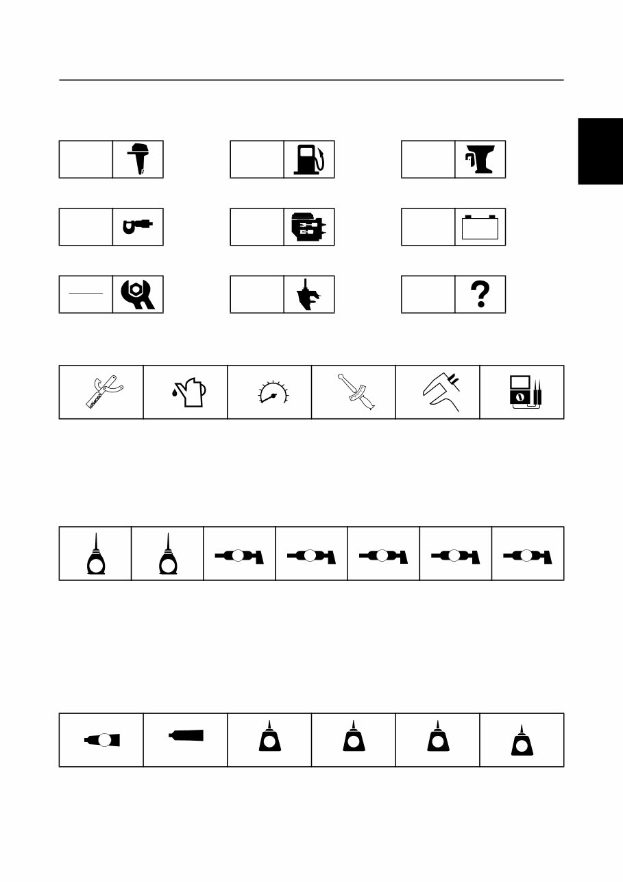
6P21H11 1-2 1 2 3 4 5 6 7 8 9 Symbol The symbols below are designed to indicate the content of a chapter. General information Specification Periodic check and adjustment Fuel system Power unit Lower unit Bracket unit Electrical system Troubleshooting GEN INFO SPEC CHK ADJ FUEL POWR LOWR BRKT ELEC TRBL SHTG – + Symbols 1 to 6 indicate specific data. 1 Special service tool 2 Specified oil or fluid 3 Specified engine speed 4 Specified tightening torque 5 Specified measurement 6 Specified electrical value (resistance, voltage, electric current) Symbols 7 to C in an exploded diagram indicate the grade of lubricant and the lubrication point. 7 Apply Yamaha 4-stroke motor oil 8 Apply gear oil 9 Apply water resistant grease (Yamaha grease A) 0 Apply molybdenum disulfide grease A Apply corrosion resistant grease (Yamaha grease D) B Apply low temperature resistant grease (Yamaha grease C) C Apply injector grease Symbols D to I in an exploded diagram indicate the type of sealant or locking agent and the appli- cation point. D Apply Gasket Maker E Apply ThreeBond 1104J F Apply LOCTITE 271 (red) G Apply LOCTITE 242 (blue) H Apply LOCTITE 572 I Apply silicon sealant 1 2 3 4 5 6 T R . . 7 8 9 0 A B C E G A M D C I D E F G H I GM 1104J 271 LT 242 LT 572 LT SS How to use this manual
GEN INFO General information 1-3 6P21H11 Abbreviation The following abbreviations are used in this service manual. Abbreviation Description ABYC American Boat and Yacht Council AFT Aft end API American Petroleum Institute BOW Bow end CCA Cold Cranking Ampere DES Dual Engine System ECM Electronic Control Module EX Exhaust IN Intake MCA Marine Cranking Ampere PCV Pressure Control Valve PON Pump Octane Number = (RON + Motor Octane Number)/2 PORT Port side PTT Power Trim and Tilt RC Reserve Capacity RON Research Octane Number SAE Society of Automotive Engineers STBD Starboard side TDC Top Dead Center TPS Throttle Position Sensor UP Upside YDIS Yamaha Diagnostic System
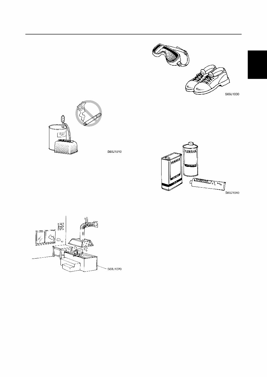
6P21H11 1-4 1 2 3 4 5 6 7 8 9 Safety while working 1 To prevent an accident or injury and to ensure quality service, follow the safety pro- cedures provided below. Fire prevention Gasoline is highly flammable. Keep gasoline and all flammable products away from heat, sparks, and open flames. Ventilation Gasoline vapor and exhaust gas are heavier than air and extremely poisonous. If inhaled in large quantities they may cause loss of consciousness and death within a short time. When test running an engine indoors (e.g., in a water tank) be sure to do so where ade- quate ventilation can be maintained. Self-protection Protect your eyes by wearing safety glasses or safety goggles during all operations involv- ing drilling and grinding, or when using an air compressor. Protect your hands and feet by wearing pro- tective gloves and safety shoes when neces- sary. Part, lubricant, and sealant Use only genuine Yamaha parts, lubricants, and sealants or those recommended by Yamaha, when servicing or repairing the out- board motor. Under normal conditions, the lubricants men- tioned in this manual should not harm or be hazardous to your skin. However, you should follow these precautions to minimize any risk when working with lubricants. 1. Maintain good standards of personal and industrial hygiene. 2. Change and wash clothing as soon as possible if soiled with lubricants. 3. Avoid contact with skin. Do not, for example, place a soiled rag in your pocket. 4. Wash hands and any other part of the body thoroughly with soap and hot water after contact with a lubricant or lubricant soiled clothing has been made. 5. To protect your skin, apply a protective cream to your hands before working on the outboard motor. How to use this manual / Safety while working
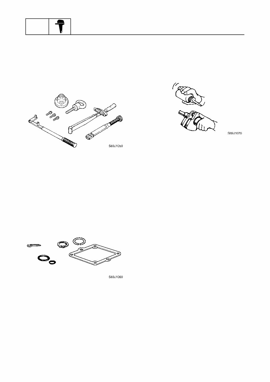
GEN INFO General information 1-5 6P21H11 6. Keep a supply of clean, lint-free cloths for wiping up spills, etc. Good working practice Special service tool Use the recommended special service tools to protect parts from damage. Use the right tool in the right manner—do not improvise. Tightening torque Follow the tightening torque specifications provided throughout the manual. When tight- ening nuts, bolts, and screws, tighten the large sizes first, and tighten fasteners starting in the center and moving outward. Non-reusable part Always use new gaskets, seals, O-rings, cot- ter pins, circlips, etc., when installing or assembling parts. Disassembly and assembly 1. Use compressed air to remove dust and dirt during disassembly. 2. Apply engine oil to the contact surfaces of moving parts before assembly. 3. Install bearings with the manufacture identification mark in the direction indi- cated in the installation procedure. In addition, be sure to lubricate the bearings liberally. 4. Apply a thin coat of water-resistant grease to the lip and periphery of an oil seal before installation. 5. Check that moving parts operate nor- mally after assembly.
Get the comprehensive 2005-2006 Yamaha 250hp (F250/LF250) Outboard Service & Repair Manual to tackle outboard problems like a pro. This manual equips you with manufacturer-provided troubleshooting and replacement procedures, complete with step-by-step instructions, clear images, and exploded-view illustrations.
Whether you're a professional mechanic or a DIY enthusiast, regular maintenance is crucial for your outboard's longevity. Over time, certain parts will wear out and require replacement. A reliable repair manual is your go-to resource, offering manufacturer-recommended troubleshooting charts and replacement procedures to get your outboard back on the water swiftly.
Not just any generic manual, this is the same OEM manual used by professional technicians. It's your all-in-one guide to saving on repairs, enhancing your outboard's reliability, and preventing issues. No more flipping through countless pages or dealing with greasy, torn, or lost pages. Access and search the manual easily, and even print it out if you prefer a physical copy.
Printable: Yes
Language: English
Compatibility: Works on various electronic devices, including PC & Mac computers, Android and Apple smartphones & tablets, etc.
Requirements: Adobe Reader (free)
Recently Viewed
5,521,897Happy Clients
2,594,462eManuals
1,120,453Trusted Sellers
15Years in Business
Price:
Actual Price:
2005-2006 Yamaha 250hp (F250/LF250) Outboard OEM Service & Repair Manual