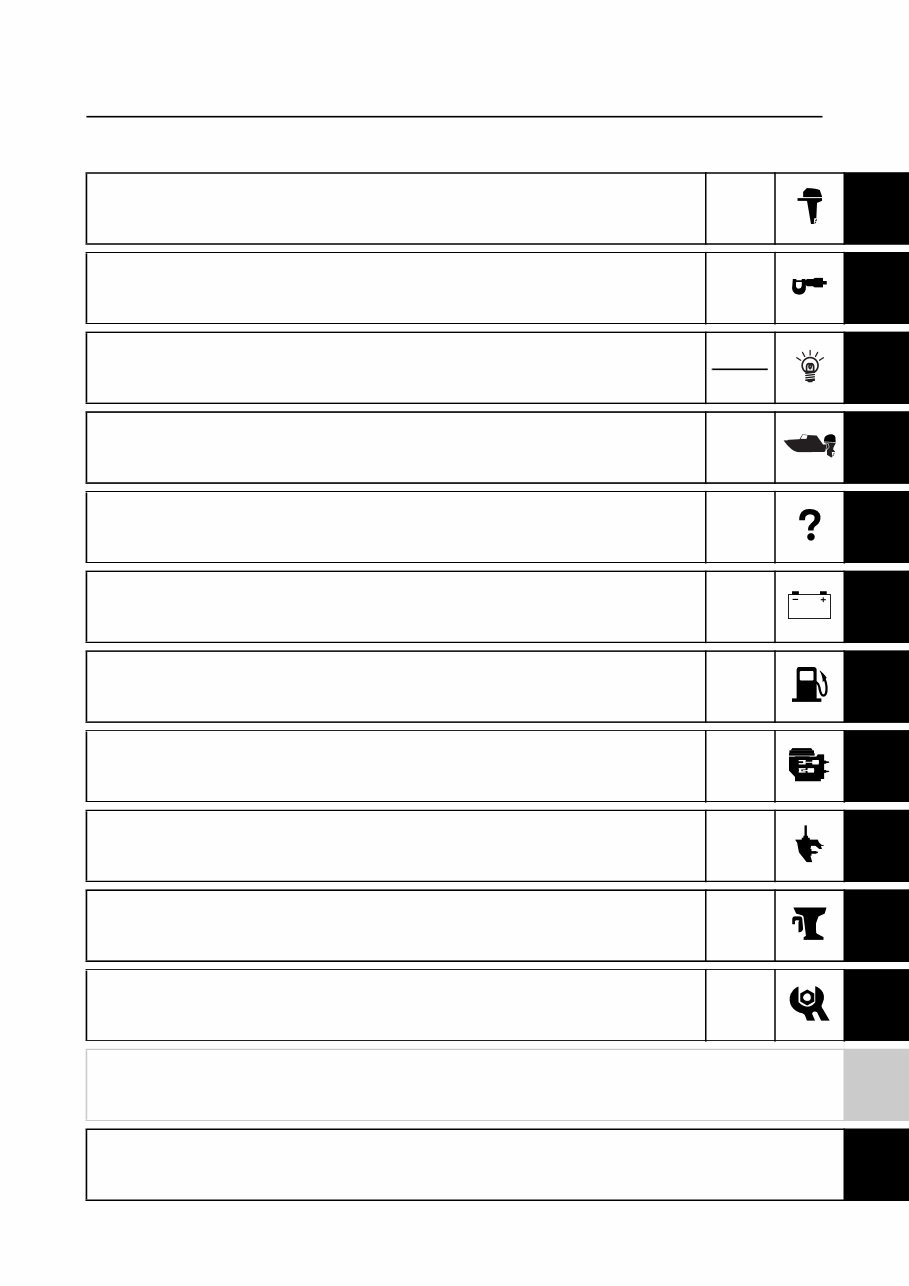
Supplementary contents General information GEN INFO 0 Specification SPEC 1 Technical features and description TECH FEA 2 Rigging information RIG GING 3 Troubleshooting TRBL SHTG 4 Electrical system ELEC 5 Fuel system FUEL 6 Power unit POWR 7 Lower unit LOWR 8 Bracket unit BRKT 9 Maintenance MNT 10 Index Appendix A
General information Safety while working................................................................. 1 Rotating part ................................................................................... 1 Hot part ........................................................................................... 1 Electric shock ................................................................................. 1 Propeller ......................................................................................... 1 Handling of gasoline ....................................................................... 1 Ventilation....................................................................................... 1 Self-protection ................................................................................ 2 Working with crane ......................................................................... 2 Handling of gas torch ..................................................................... 2 Part, lubricant, and sealant ............................................................. 2 Handling of sealant ......................................................................... 3 Special service tool ........................................................................ 3 Tightening torque ........................................................................... 3 Non-reusable part ........................................................................... 3 Disassembly and assembly ............................................................ 3 How to use this manual ................................................................ 4 Manual format ................................................................................ 4 Abbreviation ................................................................................... 5 Lubricant, sealant, and thread locking agent ......................... 6 Symbol ........................................................................................... 6 Special service tool........................................................................ 7 Specification Model feature ................................................................................... 9 Model designation .......................................................................... 9 Serial number ................................................................................. 9 Model data ...................................................................................... 10 Dimension and weight .................................................................. 10 Performance ................................................................................. 10 Power unit .................................................................................... 10 Lower unit ..................................................................................... 11 Bracket unit .................................................................................. 11 Fuel and oil requirement ............................................................... 11 Battery requirement ...................................................................... 12 PTT fluid requirement ................................................................... 12 Electrical system technical data .............................................. 12 Fuel injection control system ........................................................ 12
Y-COP (optional) .......................................................................... 12 Lower unit technical data ........................................................... 12 Lower unit assembly..................................................................... 12 Bracket unit technical data ........................................................ 13 PTT system .................................................................................. 13 Specified tightening torque ....................................................... 13 Rigging information ...................................................................... 13 Electrical system .......................................................................... 13 Fuel system .................................................................................. 13 Power unit .................................................................................... 13 Lower unit ..................................................................................... 14 PTT unit ........................................................................................ 14 General tightening torque .......................................................... 15 Technical features and description Electronic control system .......................................................... 16 Fail-safe control ............................................................................ 17 Y-COP (optional) ........................................................................... 17 Tilt limiter (optional) .................................................................... 19 Power unit system........................................................................ 20 Crankcase .................................................................................... 20 Cooling system ............................................................................. 21 Cooling diagram ........................................................................... 21 Rigging information Uncrating procedure.................................................................... 23 Installing Y-COP (optional) ........................................................ 24 Registering the receiver ID to the ECM ........................................ 24 Installing the tilt limiter (optional) .................................................. 25 Setting the tilt limiter (optional) ..................................................... 29 Deactivating the tilt limiter (optional) ............................................ 30
System diagram ............................................................................ 31 Single outboard motor application ................................................ 31 Troubleshooting YDIS .................................................................................................. 33 Trouble code table........................................................................ 33 Troubleshooting the power unit using the YDIS ........................... 33 Trouble code and checking step .................................................. 33 Electrical system Wiring harness routing ............................................................... 34 Port ............................................................................................... 34 Starboard...................................................................................... 36 Top ............................................................................................... 40 Bottom cowling ............................................................................. 41 Fuel control unit and component ............................................ 43 Checking the low-pressure fuel pump and high-pressure fuel pump............................................................... 43 Y-COP (optional) ........................................................................... 45 Checking Y-COP .......................................................................... 46 Checking the buzzer ..................................................................... 46 Checking the Y-COP main wiring harness ................................... 46 Checking the button cell battery ................................................... 47 PTT electrical system .................................................................. 48 Checking the tilt limiter (optional) ................................................. 48 Fuel system Hose routing .................................................................................. 50 Cooling water hose....................................................................... 50 Vapor separator ............................................................................ 52 Removing the vapor separator ..................................................... 54 Installing the vapor separator ....................................................... 54
Power unit Junction box .................................................................................. 55 Removing the Rectifier Regulator ................................................ 57 Removing the junction box ........................................................... 57 Installing the junction box ............................................................. 58 Installing the Rectifier Regulator .................................................. 58 Oil cooler and oil pump assembly ........................................... 60 Removing the oil cooler ................................................................ 63 Installing the oil cooler .................................................................. 63 Cylinder block sensor and switch ........................................... 64 Removing the cooling water cover ............................................... 67 Removing the thermostat ............................................................. 67 Checking the cooling water cover anode ..................................... 67 Installing the thermostat ............................................................... 67 Installing the cooling water cover ................................................. 68 Cylinder block ............................................................................... 69 Disassembling the cylinder block ................................................. 71 Assembling the cylinder block ...................................................... 72 Lower unit Lower unit ....................................................................................... 76 Drive shaft and lower case ........................................................ 78 Disassembling the lower case ...................................................... 80 Assembling the drive shaft ........................................................... 80 Installing the lower unit ................................................................. 82 Shimming ........................................................................................ 83 Measuring the forward gear backlash and reverse gear backlash before disassembly .................................. 83 Shimming ..................................................................................... 86 Shim location ................................................................................ 86 Measuring the forward gear backlash .......................................... 87 Measuring the reverse gear backlash .......................................... 87 Adjusting the reverse gear shim (T2) thickness ........................... 87 Reverse gear shim (T2) selection chart ....................................... 89
Bracket unit PTT unit ........................................................................................... 91 Checking the hydraulic pressure .................................................. 91 PTT cylinder ................................................................................... 93 Bleeding the PTT unit ................................................................... 93 Maintenance Outline ............................................................................................. 95 Maintenance chart 1 ..................................................................... 95 Maintenance chart 2 ..................................................................... 97 General periodic maintenance.................................................. 98 Checking the cooling water passage............................................ 98 Changing gear oil ......................................................................... 98 Appendix Wiring diagram ............................................................................ 101 How to use the wiring diagram ................................................... 101
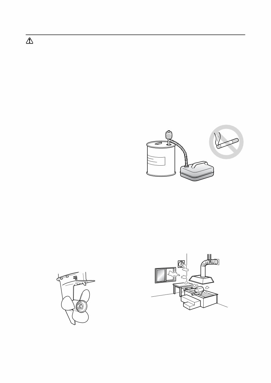
1 Safety while working To prevent an accident or injury and to pro- vide quality service, observe the following safety procedures. Rotating part • Hands, feet, hair, jewelry, clothing, per- sonal flotation device straps, and so on, can become entangled with internal rotating parts of the engine, resulting in serious injury or death. • Keep the top cowling installed whenever possible. Do not remove or install the top cowling when the engine is running. • Only operate the engine with the top cowl- ing removed according to the specific instructions in the manual. Keep hands, feet, hair, jewelry, clothing, personal flota- tion device straps, and so on, away from any exposed moving parts. Hot part During and after operation, engine parts are hot enough to cause burns. Do not touch any parts under the top cowling until the engine has cooled. Electric shock Do not touch any electrical parts while start- ing or operating the engine. Otherwise, shock or electrocution could result. Propeller Do not hold the propeller with your hands when loosening or tightening the propeller nut. Handling of gasoline • Gasoline is highly flammable. Keep gaso- line and all flammable products away from heat, sparks, and open flames. • Gasoline is poisonous and can cause injury or death. Handle gasoline with care. Never siphon gasoline by mouth. If you swallow some gasoline, inhale a lot of gasoline vapor, or get some gasoline in your eyes, see your doctor immediately. If gasoline spills on your skin, wash with soap and water. If gasoline spills on your clothing, change your clothes. Ventilation • Gasoline vapor and exhaust gas are heavier than air and extremely poisonous. If gasoline vapor or exhaust gas is inhaled in large quantities, it may cause loss of con- sciousness and death within a short time. • When test running an engine indoors (for example, in a water tank) make sure to do so where adequate ventilation can be main- tained. General information
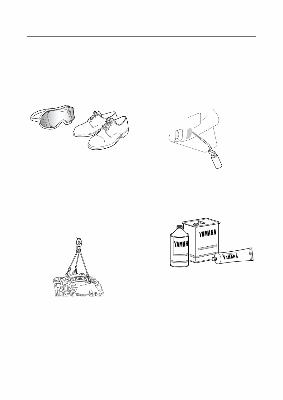
2 Self-protection • Protect your eyes by wearing safety glasses or safety goggles during all opera- tions involving drilling and grinding, or when using an air compressor. • Protect your hands and feet by wearing protective gloves and safety shoes when necessary. Working with crane • Outboard motors weighing 18.0 kg (39.7 lb) and over must be carried by a crane. • Use the wire ropes of adequate strength, and lift up the outboard motor using the three point suspension. • If the outboard motor does not have three or more points to be suspended, support it using additional ropes, or the like, so that the outboard motor can be lifted and carried in a stable manner. Handling of gas torch • Improper handling of a gas torch may result in burns. For information on the proper han- dling of the gas torch, see the operation manual issued by the manufacturer. • When using a gas torch, keep it away from the gasoline and oil, to prevent a fire. • Components become hot enough to cause burns. Do not touch any hot components directly. Part, lubricant, and sealant Use only genuine Yamaha parts, lubricants, and sealants, or those recommended by Yamaha, when servicing or repairing the out- board motor.
Yamaha 200/225/250HP (VF200/VF225/VF250) Outboards OEM Service & Repair Manual
Models covered:
Yamaha VF200
Yamaha VF225
Yamaha VF250
The Yamaha 200/225/250HP (VF200/VF225/VF250) Outboards Service & Repair Manual provides an in-depth technical guide for the maintenance and repair of these high-performance outboard engines. Covering essential systems such as fuel injection, cooling, electrical components, and engine diagnostics, this manual offers detailed, step-by-step procedures for routine servicing and complex mechanical repairs.
With precise technical diagrams, factory specifications, and comprehensive troubleshooting instructions, this manual ensures that every repair is performed to Yamaha's exact standards. Whether you're maintaining the fuel system, troubleshooting engine performance issues, or performing electrical diagnostics, this guide provides the clarity and accuracy needed for reliable repairs.
Available in a convenient digital format, this manual offers easy access to critical repair information wherever you are—whether dockside or in the workshop. It's an indispensable resource for ensuring that your Yamaha 200/225/250HP outboard engines operate at peak performance, delivering reliable power on the water.
Printable: Yes Language: English Compatibility: Pretty much any electronic device, incl. PC & Mac computers, Android and Apple smartphones & tablet, etc. Requirements: Adobe Reader (free)
Recently Viewed
5,521,897Happy Clients
2,594,462eManuals
1,120,453Trusted Sellers
15Years in Business
Price:
Actual Price:
Yamaha 200/225/250HP (VF200/VF225/VF250) Outboards OEM Service & Repair Manual