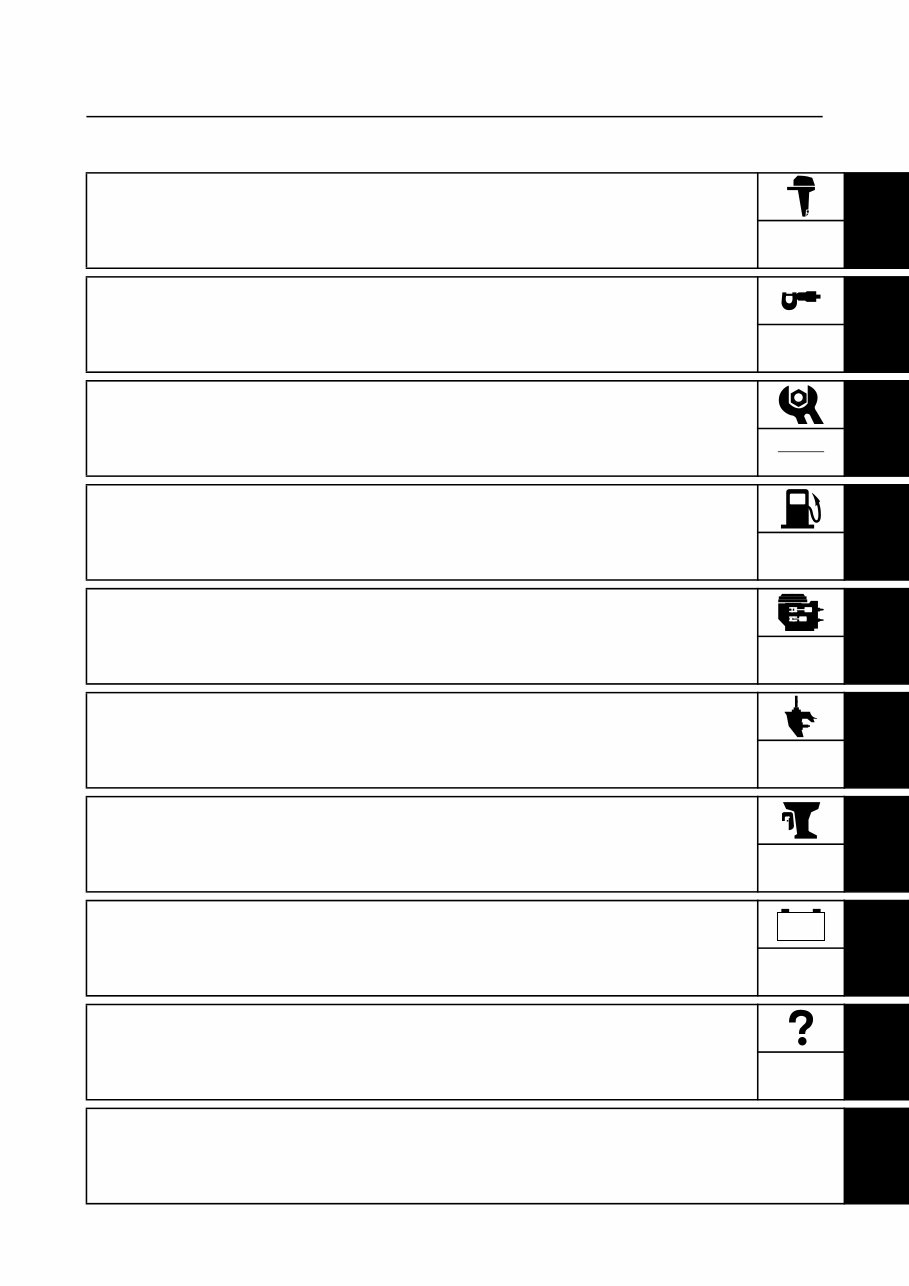
Contents General information 1 GEN INFO Specifications 2 SPEC Periodic checks and adjustments 3 CHK ADJ Fuel system 4 FUEL Power unit 5 POWR Lower unit 6 LOWR Bracket unit 7 BRKT Electrical systems 8 ELEC Troubleshooting 9 TRBL SHTG Index – +
GEN INFO 69J1D11 General information How to use this manual ................................................................................. 1-1 Manual format............................................................................................ 1-1 Symbols ..................................................................................................... 1-2 Safety while working...................................................................................... 1-3 Fire prevention........................................................................................... 1-3 Ventilation .................................................................................................. 1-3 Self-protection ........................................................................................... 1-3 Parts, lubricants, and sealants .................................................................. 1-3 Good working practices ............................................................................. 1-4 Disassembly and assembly ....................................................................... 1-4 Identification ................................................................................................... 1-4 Applicable models ..................................................................................... 1-4 Serial number ............................................................................................ 1-4 Features and benefits .................................................................................... 1-6 Newly developed V6 4-stroke engine ........................................................ 1-6 Valve train system ..................................................................................... 1-9 Intake system .......................................................................................... 1-11 Exhaust system ....................................................................................... 1-11 Fuel system ............................................................................................. 1-13 PTT (Power trim and tilt) unit ................................................................... 1-17 Technical tips ............................................................................................... 1-18 Fuel injection control ................................................................................ 1-18 Fail-safe function table ............................................................................ 1-20 PTT (Power trim and tilt) unit ................................................................... 1-21 Cooling system ........................................................................................ 1-26 Lubrication system................................................................................... 1-26 Propeller selection ....................................................................................... 1-27 Propeller size ........................................................................................... 1-27 Selection .................................................................................................. 1-27
69J1D11 1 2 3 4 5 6 7 8 9 Predelivery checks ...................................................................................... 1-28 Checking the fuel system ........................................................................ 1-28 Checking the gear oil ............................................................................... 1-28 Checking the engine oil ........................................................................... 1-28 Checking the battery................................................................................ 1-28 Checking the outboard motor mounting height ........................................ 1-29 Checking the remote control cables ........................................................ 1-29 Checking the steering wheel ................................................................... 1-30 Checking the gearshift and throttle operation .......................................... 1-30 Checking the tilt system........................................................................... 1-30 Checking the engine start switch and engine stop lanyard switch .......... 1-30 Checking the cooling water pilot hole ...................................................... 1-31 Test run ................................................................................................... 1-31 Break-in ................................................................................................... 1-31 After test run ............................................................................................ 1-31
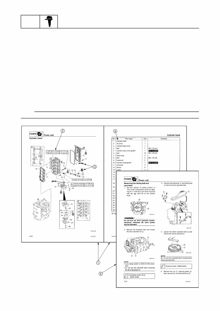
GEN INFO General information 1-1 69J1D11 How to use this manual 1 Manual format The format of this manual has been designed to make service procedures clear and easy to under- stand. Use the information below as a guide for effective and quality service. 1 Parts are shown and detailed in an exploded diagram and are listed in the components list. 2 Tightening torque specifications are provided in the exploded diagrams and after a numbered step with tightening instructions. 3 Symbols are used to indicate important aspects of a procedure, such as the grade of lubricant and lubrication point. 4 The components list consists of parts and part quantities, as well as bolt, screw, O-ring, and hose dimensions. 5 Service points regarding removal, checking, and installation are shown in individual illustrations to explain the relevant procedure. NOTE: For troubleshooting procedures, see Chapter 9, “Troubleshooting.”
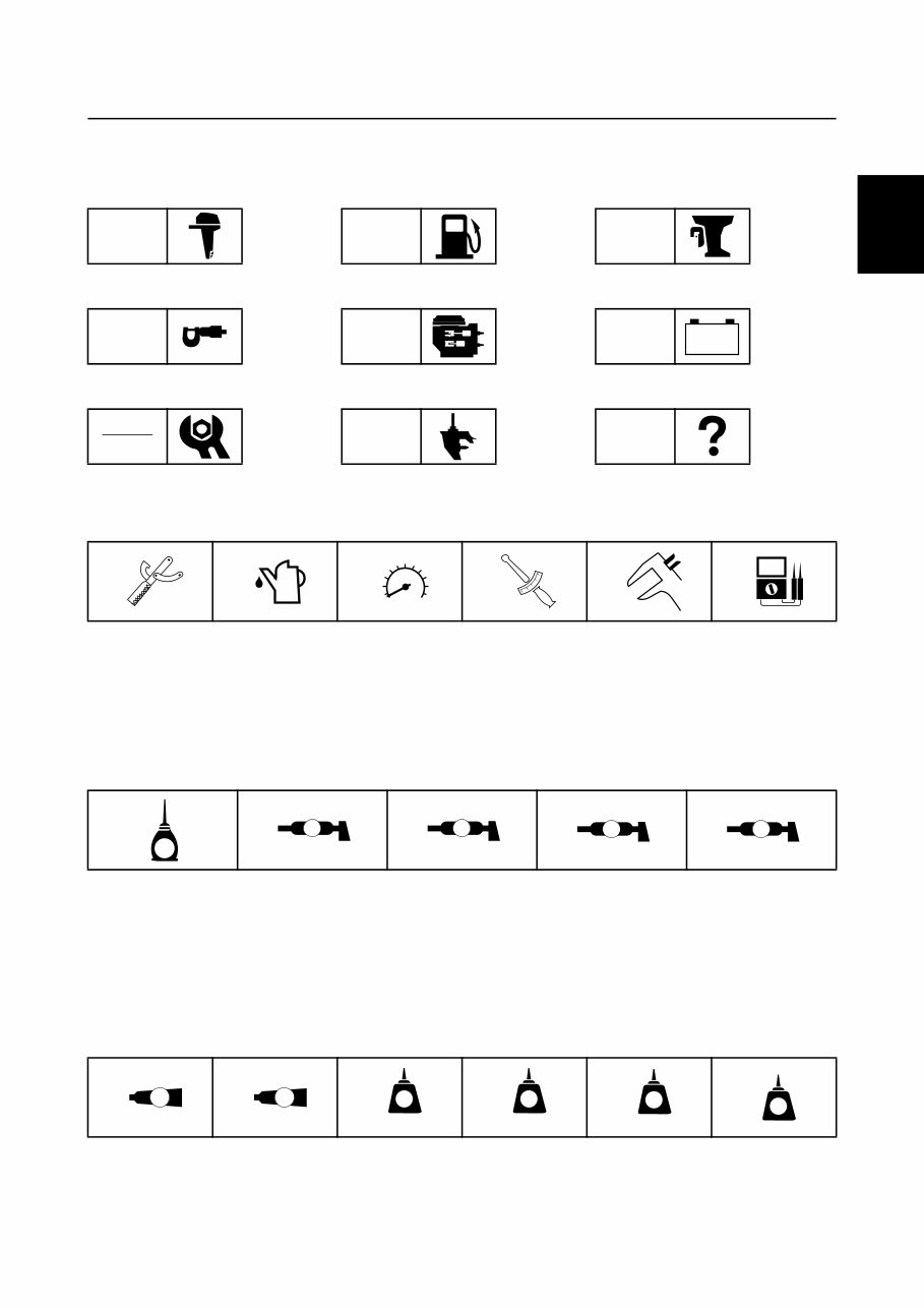
69J1D11 1-2 1 2 3 4 5 6 7 8 9 Symbols The symbols below are designed to indicate the content of a chapter. General information Specifications Periodic checks and adjustments Fuel system Power unit Lower unit Bracket unit Electrical systems Troubleshooting GEN INFO SPEC CHK ADJ FUEL POWR LOWR BRKT ELEC TRBL SHTG – + Symbols 1 to 6 indicate specific data. 1 Special tool 2 Specified oil or fluid 3 Specified engine speed 4 Specified tightening torque 5 Specified measurement 6 Specified electrical value (resistance, voltage, electric current) Symbols 7 to A in an exploded diagram indicate the grade of lubricant and the lubrication point. 7 Apply Yamaha 4-stroke motor oil 8 Apply water resistant grease (Yamaha grease A) 9 Apply molybdenum disulfide grease 0 Apply corrosion resistant grease (Yamaha grease D) A Apply low temperature resistant grease (Yamaha grease C) Symbols B to G in an exploded diagram indicate the type of sealant or locking agent and the appli- cation point. B Apply Gasket Maker ® C Apply Yamabond No. 4 D Apply LOCTITE ® No. 271 (Red) E Apply LOCTITE ® No. 242 (Blue) F Apply LOCTITE ® No. 572 G Apply silicon sealant 1 2 3 4 5 6 T R . . 7 8 9 0 A E A M D C B C D E F G GM 4 271 LT 242 LT 572 LT SS How to use this manual
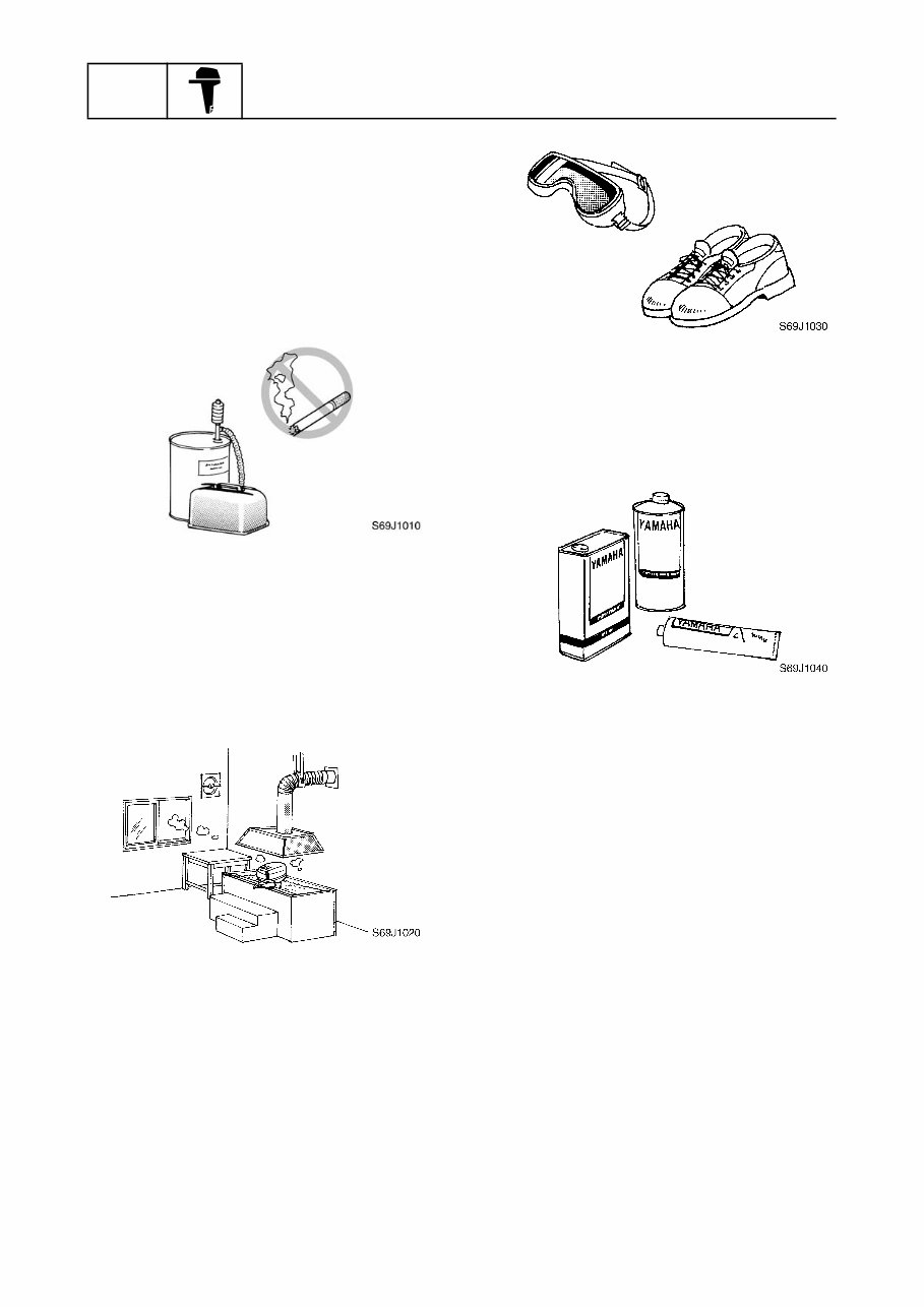
GEN INFO General information 1-3 69J1D11 Safety while working 1 To prevent an accident or injury and to ensure quality service, follow the safety pro- cedures provided below. Fire prevention Gasoline is highly flammable. Keep gasoline and all flammable products away from heat, sparks, and open flames. Ventilation Gasoline vapor and exhaust gas are heavier than air and extremely poisonous. If inhaled in large quantities they may cause loss of consciousness and death within a short time. When test running an engine indoors (e.g., in a water tank) be sure to do so where ade- quate ventilation can be maintained. Self-protection Protect your eyes by wearing safety glasses or safety goggles during all operations involv- ing drilling and grinding, or when using an air compressor. Protect your hands and feet by wearing pro- tective gloves and safety shoes when neces- sary. Parts, lubricants, and sealants Use only genuine Yamaha parts, lubricants, and sealants or those recommended by Yamaha, when servicing or repairing the outboard motor. Under normal conditions, the lubricants men- tioned in this manual should not harm or be hazardous to your skin. However, you should follow these precautions to minimize any risk when working with lubricants. 1. Maintain good standards of personal and industrial hygiene. 2. Change and wash clothing as soon as possible if soiled with lubricants. 3. Avoid contact with skin. Do not, for example, place a soiled rag in your pocket. 4. Wash hands and any other part of the body thoroughly with soap and hot water after contact with a lubricant or lubricant soiled clothing has been made. 5. To protect your skin, apply a protective cream to your hands before working on the outboard motor.
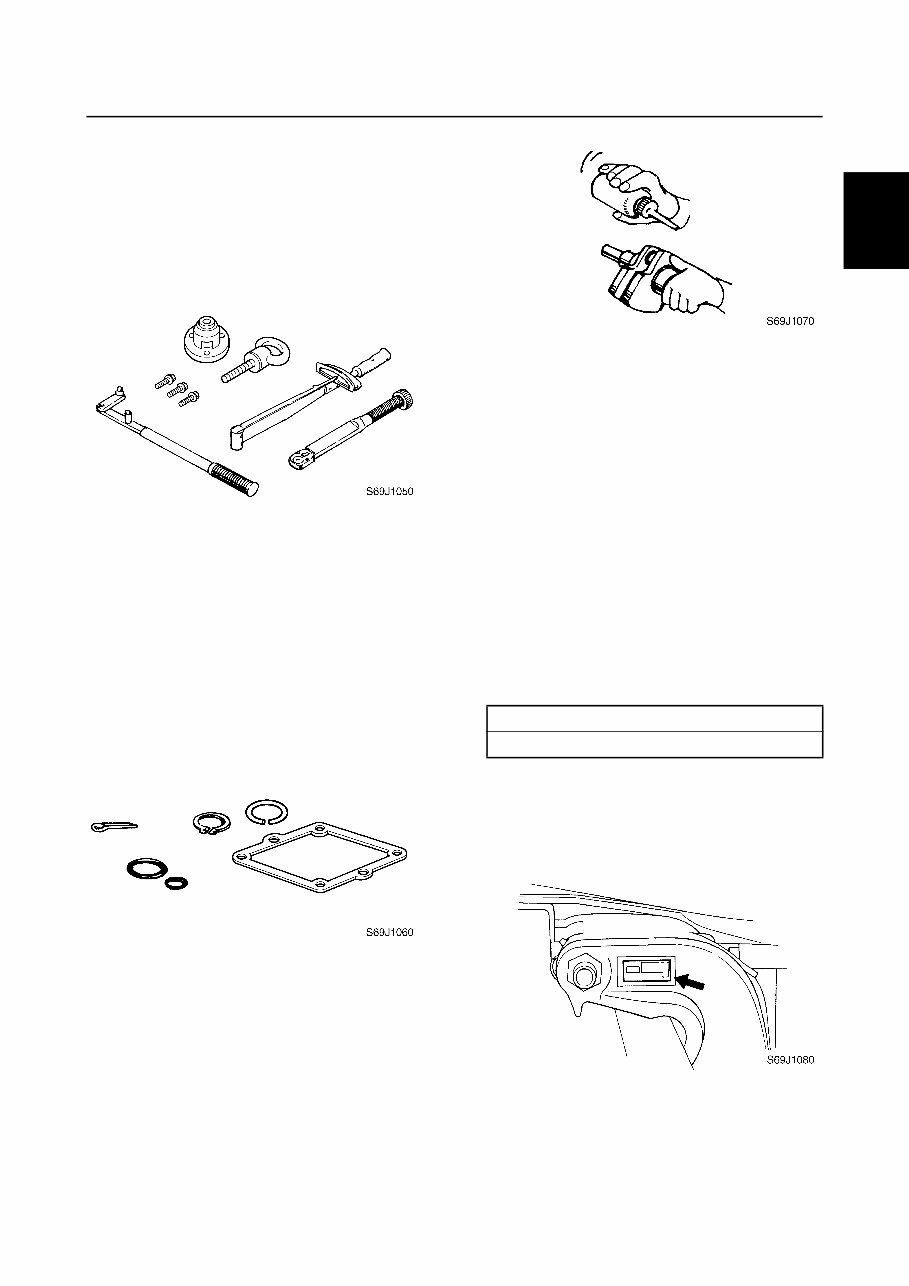
69J1D11 1-4 1 2 3 4 5 6 7 8 9 6. Keep a supply of clean, lint-free cloths for wiping up spills, etc. Good working practices Special tools Use the recommended special tools to pro- tect parts from damage. Use the right tool in the right manner—do not improvise. Tightening torques Follow the tightening torque specifications provided throughout the manual. When tight- ening nuts, bolts, and screws, tighten the large sizes first, and tighten fasteners starting in the center and moving outward. Non-reusable parts Always use new gaskets, seals, O-rings, cot- ter pins, circlips, etc., when installing or assembling parts. Disassembly and assembly 1. Use compressed air to remove dust and dirt during disassembly. 2. Apply engine oil to the contact surfaces of moving parts before assembly. 3. Install bearings with the manufacture identification mark in the direction indi- cated in the installation procedure. In addition, be sure to lubricate the bearings liberally. 4. Apply a thin coat of water-resistant grease to the lip and periphery of an oil seal before installation. 5. Check that moving parts operate nor- mally after assembly. Identification 1 Applicable models This manual covers the following models. Serial number The outboard motor serial number is stamped on a label attached to the port clamp bracket. Applicable models F200TR, LF200TR, F225TR, LF225TR Safety while working / Identification
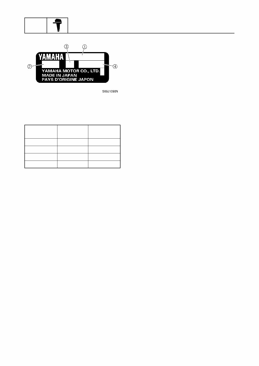
GEN INFO General information 1-5 69J1D11 1 Model name 2 Approved model code 3 Transom height 4 Serial number Model name Approved model code Starting serial No. F200TR 60L 1001799– LF200TR 60M 1000373– F225TR 69J 1007259– LF225TR 69K 1002513–
2003-2009 Yamaha 225HP (F225C/LF225C) Outboards OEM Service & Repair Manual
Models covered:
Yamaha F225C
Yamaha LF225C
This OEM service and repair manual for 2003-2009 Yamaha 225HP outboards, including models F225C and LF225C, provides comprehensive, factory-approved procedures for maintenance, diagnostics, and repairs. Tailored to meet Yamaha’s exact specifications, it covers everything necessary to keep these outboard engines operating at peak performance.
The manual includes detailed instructions for key systems such as the V6 four-stroke engine, fuel injection system, cooling, lubrication, ignition, and electrical components. Factory-authorized wiring diagrams, torque specifications, and exploded parts views ensure accurate servicing for tasks ranging from routine oil changes to in-depth mechanical overhauls.
Available in digital format for convenient access, this manual is an essential tool for marine mechanics and boat owners. Whether you’re maintaining your outboard for recreational use or commercial operations, it delivers precise guidance to ensure long-term reliability and efficient performance of Yamaha 225HP outboards.
Printable: Yes Language: English Compatibility: Pretty much any electronic device, incl. PC & Mac computers, Android and Apple smartphones & tablet, etc. Requirements: Adobe Reader (free)
Recently Viewed
5,521,897Happy Clients
2,594,462eManuals
1,120,453Trusted Sellers
15Years in Business
Price:
Actual Price:
2003-2009 Yamaha 225HP (F225C/LF225C) Outboards OEM Service & Repair Manual