Yamaha 20/25HP (F20/F25) Outboards OEM Service & Repair Manual
What's Included?
Lifetime Access
Fast Download Speeds
Online & Offline Access
Access PDF Contents & Bookmarks
Full Search Facility
Print one or all pages of your manual
65W-28197-Z8-C2 290362 SERVICE MANUAL MANUEL D’ENTRETIEN WARTUNGSHANDBUCH MANUAL DE SERVICIO E F D ES F20A, F25A WORLD WIDE USA, CANADA F25X
E A20000-1 NOTICE This manual has been prepared by the Yamaha Motor Company Ltd. primarily for use by Yamaha dealers and their trained mechanics when performing maintenance procedures and repairs to Yamaha equipment. It has been written to suit the needs of persons who have a basic understanding of the mechanical and electrical concepts and procedures inherent in the work, for without such knowledge attempted repairs or service to the equipment could render it unsafe or unfit for use. Because the Yamaha Motor Company, Ltd. has a policy of continuously improving its prod- ucts, models may differ in detail from the descriptions and illustrations given in this publica- tion. Use only the latest edition of this manual. Authorized Yamaha dealers are notified periodically of modifications and significant changes in specifications and procedures, and these are incorporated in successive editions of this manual. A10001-0* F20A, F25A SERVICE MANUAL 1998 Yamaha Motor Co., Ltd. 2nd Edition, October 1998 All rights reserved. No part of this publication may be reproduced or transmitted in any form or by any means including photocopying and recording without the written permission of the copyright holder. Such written permission must also be obtained before any part of this publication is stored in a retrieval system of any nature. Printed in Japan P/N 65W-28197-Z8-C2
F D ES A20000-1 AVANT-PROPOS Ce manuel a été préparé par la Yamaha Motor Company principalement à l’intention des concessionnaires Yamaha et de leurs mécaniciens qualifiés afin de les assister lors de l’entretien et la répa- ration des produits Yamaha. Ce manuel est destiné à des personnes possédant les connaissances de base en mécanique et en électricité sans lesquelles l’exécution de réparations ou d’entretiens peut ren- dre les machines impropres ou dangereu- ses à l’emploi. La Yamaha Motor Company, Ltd. s’efforce en permanence d’améliorer ses produits. Par conséquent, il se peut que les modèles diffèrent légèrement des descriptions et illustrations de ce manuel. Les modifications et les change- ments significatifs dans les caractéristi- ques ou les procédés sont notifiés à tous les concessionnaires Yamaha et sont publiés dans les éditions ultérieures de ce manuel. A10001-0* F20A, F25A MANUEL D’ENTRETIEN 1998 Yamaha Motor Co., Ltd. 2e édition, octobre 1998 Tous droits réservés. Toute reproduction ou transmission de ce manuel, même partielle, par quelque procédé que ce soit, y com- pris par photocopie ou enregistre- ment, requiert l’accord écrit préalable de la Yamaha Motor Co., Ltd. De même, l’introduction de toute partie de ce manuel dans un système d’archivage requiert cet accord écrit préalable. Imprimé au Japon P/N 65W-28197-Z8-C2 A20000-1 HINWEIS Dieses Handbuch wurde von der Yamaha Motor Company, Ltd. vor- rangig für Yahama-Vertragshändler und deren qualifizierte Mechaniker geschrieben, um sie bei der Durch- führung von Wartungs- und Repa- raturarbeiten an Yamaha-Motoren zu unterstützen. Es werden Grund- kenntnisse der mechanischen und elektrischen Wirkungsweise und der Arbeitsverfahren vorausge- setzt, denn ohne diese Grundkennt- nisse versuchte Wartungs- und Reparaturarbeiten machen das Pro- dukt eher unsicher oder sogar gebrauchsunfähig. Die Yamaha Motor Company, Ltd. ist stets bestrebt, ihre Produkte ständig zu verbessern. Einzelne Modelle können im Detail von den hier enthaltenen Beschreibungen und Abbildungen abweichen. Benutzen Sie immer nur die neue- ste Ausgabe dieses Handbuchs. Autorisierte Yamaha-Vertrags- händler werden regelmäßig vorab über Modifikationen und wesentli- che Änderungen der technischen Daten und Verfahren unterrichtet, die in der jeweils nächsten Ausga- ben dieses Handbuchs eingearbei- tet werden. A10001-0* F20A, F25A WARTUNGSHANDBUCH 1998 Yamaha Motor Co., Ltd. 2. Ausgabe, Oktober 1998 Alle Rechte vorbehalten. Diese Veröffentlichung darf auch teilweise in keiner Weise oder durch irgendein Verfahren ohne die schriftlichts Genehmigung des Urheberrechts-Inhabers reproduziert oder übertragen werden. Dies gilt auch für Foto- kopien und Aufzeichnungen. Die schriftliche Genehmigung ist vor der Übernahme in irgendein Informationssystem einzuholen. Gedruckt in Japan P/N 65W-28197-Z8-C2 A20000-1 AVISO Este manual ha sido preparado por Yamaha Motor Company Ltd. principal- mente para que lo empleen los concesio- narios Yamaha y sus mecánicos cualificados al llevar a cabo los procedi- mientos de mantenimiento y de repara- ción de los equipos Yamaha. Se ha escrito para adaptarlo a las necesidades de las personas que ya tienen un conoci- miento básicos de los conceptos mecáni- cos y eléctricos y de los procedimientos inherentes al trabajo, porque sin tales conocimientos las reparaciones o el ser- vicio del equipo podría dejar el equipo inseguro o inadecuado para la utiliza- ción. Puesto que Yamaha Motor Company, Ltd. sigue una política de mejora conti- nua de sus productos, los modelos pue- den diferir en detalles de las descripciones e ilustraciones dadas en esta publicación. Emplee sólo la última edición de este manual. Se notifica periódicamente a los concesionarios autorizados Yamaha sobre las modifica- ciones y cambios importantes en las especificaciones y procedimientos, y tales cambios se incorporan en las edi- ciones subsiguientes de este manual. A10001-0* F20A, F25A MANUAL DE SERVICIO 1998 Yamaha Motor Co., Ltd. 2ª Edición, octubre 1998 Reservados todos los derechos. Queda prohibida la reproducción o transmisión de esta publicación, ya sea en su totalidad o en parte, y por cualquier medio, incluido su fotoco- piado o grabación, sin el consenti- miento por escrito del titular del derecho de copyright. También deberá obtenerse este consenti- miento antes de proceder al almace- namiento de cualquier parte de esta publicación en un sistema de bús- queda documental de cualquier natu- raleza. Impreso en Japón P/N˚ 65W-28197-Z8-C2
E HOW TO USE THIS MANUAL MANUAL FORMAT All of the procedures in this manual are organized in a sequential, step-by-step format. The information has been compiled to provide the mechanic with an easy to read, handy refer- ence that contains comprehensive explanations of all disassembly, repair, assembly, and inspection operations. In this revised format, the condition of a faulty component will precede an arrow symbol and the course of action required will follow the symbol, e.g., ● Bearings Pitting/scratches → Replace. To assist you in finding your way through this manual, the section title and major heading is given at the top of every page. ILLUSTRATIONS The illustrations within this service manual represent all of the designated models. CROSS REFERENCES The cross references have been kept to a minimum. Cross references will direct you to the appropriate section or chapter.
F D ES STRUCTURE DU MANUEL FORMAT DU MANUEL Tous les procédés repris dans ce manuel sont décrits pas à pas. Les informations ont été condensées pour fournir au méca- nicien un guide pratique et facile à lire, contenant des explications claires pour tous les procédés de démontage, de répa- ration, de remontage et de vérification. L’état d’une pièce défectueuse est men- tionné et est suivi d’une flèche et de la mesure à prendre pour chaque symptôme décelé. Ainsi, par exemple: ● Roulements Piqûres/endommagements → Remplacer. Pour plus de facilité, le nom du chapitre et les titres principaux figurent à l’en- tête de chaque page. ILLUSTRATIONS Les illustrations représentent les modè- les désignés. RENVOIS Les renvois ont été évités au maximum. Les renvois réfèrent à la section ou au chapitre appropriés. BENUTZUNG DIESES HANDBUCHS AUFBAU Alle in diesem Handbuch enthalte- nen Verfahren sind in der richtigen Reihenfolge Schritt für Schritt beschrieben. Die Informationen wurden so aufbereitet, daß dem Mechaniker in leicht verständli- cher, handlicher Form alle not- wendigen Handgriffe beim Zerlegen, bei der Reparatur und dem Zusammenbau sowie bei der Inspektion ausführlich erklärt wer- den. Bei dieser neuen Darstellungs- weise folgt nach der Zustandsbe- schreibung eines schadhaften Teils ein Pfeil, der auf die notwen- dige Aktion hinweist, z.B: ● Lager Lochfraß/Kratzer → Erset- zen. Die Abschnittstitel finden sich zur Bezugnahme in der Kopfzeile wie- der. ABBILDUNGEN Die Abbildungen in diesem War- tungshandbuch gelten für alle angegebenen Modelle. QUERVERWEISE Querverweise wurden auf ein Minimum beschränkt. Querver- weise führen Sie zum entspre- chenden Abschnitt oder Kapitel. CÓMO EMPLEAR ESTE MANUAL FORMATO DEL MANUAL Todos los procedimientos de este manual están organizados en un formato de paso a paso secuencial. La informa- ción ha sido compilada para proporcio- nar al mecánico una referencia útil y de fácil lectura que contiene detalladas explicaciones de todas las operaciones de desmontaje, reparación, montaje e inspección. En este formato revisado, el estado de un componente averiado irá seguido de un símbolo de flecha y de la acción reque- rida detrás de la fecha, por ejemplo: ● Cojinetes Picadas/rayadas → Reemplazar. Para ayudarle a encontrar lo que busca en este manual, el título de la sección y el encabezamiento principal se incluye al principio de cada página. ILUSTRACIONES Las ilustraciones de este manual de ser- vicio representan a todos los modelos designados. REFERENCIAS DE CONSULTA Las referencias de consulta se han man- teniendo al mínimo. Estas referencias indican la sección o capítulo que debe consultarse.
E IMPORTANT INFORMATION In this Service Manual particularly important information is distinguished in the following ways. The Safety Alert Symbol means ATTENTION! BECOME ALERT! YOUR SAFETY IS INVOLVED! WARNING Failure to follow WARNING instructions could result in severe injury or death to the machine operator, a bystander, or a person inspecting or repairing the outboard motor. CAUTION: A CAUTION indicates special precautions that must be taken to avoid damage to the out- board motor. NOTE: A NOTE provides key information to make procedures easier or clearer.
F D ES INFORMATIONS IMPORTANTES Les informations particulièrement importantes sont repérées par les nota- tions suivantes. Le symbole d’alerte sécurité signifie ATTENTION! SOYEZ ATTENTIF! VOTRE SECURITE EST MENA- CEE! AVERTISSEMENT Le non-respect d’une instruction AVERTISSEMENT peut blesser ou entraîner la mort de l’opérateur, d’un passager ou d’une personne inspectant ou réparant le moteur hors-bord. ATTENTION: ATTENTION indique les consignes qui doivent être respectées afin d’évi- ter d’endommager le moteur hors- bord. N.B.: N.B. donne des informations importan- tes qui facilitent et expliquent les diffé- rentes opérations. WICHTIGE INFORMATION Informationen in diesem War- tungshandbuch, die von besonde- rer Wichtigkeit sind, werden auf eine der folgenden Arten hervor- gehoben. Dieses Warnsymbol bedeutet: VORSICHT! ES GEHT UM IHRE SICHERHEIT! WARNUNG Eine WARNUNG enthält Anwei- sungen, die eingehalten werden müssen, um Verletzungen, mögli- cherweise sogar mit Todesfolge, für Bediener, in der Nähe befindli- che Personen oder Techniker, die Inspektionen oder Reparaturen an Außenbordmotoren vorneh- men, zu vermeiden. ACHTUNG: Unter ACHTUNG finden Sie spezi- elle Vorsichtsmaßnahmen, die eingehalten werden müssen, um Beschädigungen am Außenbord- motor zu vermeiden. HINWEIS: Ein HINWEIS enthält Informatio- nen, die einen Vorgang einfacher oder deutlicher machen. INFORMACIÓN IMPORTANTE En este manual de servicio, la informa- ción particularmente importante se dis- tingue según se indica a continuación. El símbolo de alerta de seguridad significa ¡ATENCION, ESTA EN JUEGO SU PROPIA SEGURIDAD! ATENCION El incumplimiento de este tipo de ins- trucciones de ATENCION puede cau- sar graves lesiones, e incluso la muerte, al operador del motor, a las personas a su alrededor o al técnico que inspeccione o repare el motor fuera de borda. PRECAUCION: Una instrucción de PRECAUCION indica precauciones especiales que debe observar para evitar dañar el motor fuera de borda. NOTA: La NOTA proporciona información clave que facilita o clarifica determina- dos procedimientos.
E HOW TO USE THIS MANUAL 1 To help identify parts and clarify procedure steps, there are exploded diagrams at the start of each removal and disassembly section. 2 Numbers are given in the order of the jobs in the exploded diagram. A circled number indicates a disassembly step. 3 Symbols indicate parts to be lubricated or replaced (see “SYMBOLS”). 4 A job instruction chart accompanies the exploded diagram, providing the order of jobs, names of parts, notes in jobs, etc. Example: O-ring size 39.5 × 2.5 mm: Inside diameter (D) × Ring diameter (d) 5 Dimension figures and the number of parts, are provided for fasteners that require a tight- ening torque. Example: Bolt or screw size : M10 (D) × 25 mm (L) (2 pieces) 6 Jobs requiring more information (such as special tools and technical data) are described sequentially. d D 10 × 25 mm (2) D L
F D ES ORGANISATION DES INFORMATIONS 1 Chaque section de dépose et de démontage est précédée de vues en éclaté rendant plus faciles les étapes du travail et l’identification des pié- ces. 2 Sur les vues en éclaté, les pièces sont numérotées dans l’ordre des opéra- tions à effectuer. Un chiffre entouré d’un cercle correspond à une étape de démontage. 3 Des symboles repèrent les pièces à lubrifier ou à remplacer (se reporter à “SYMBOLES”). 4 Un tableau accompagne les vues en éclaté. Celui-ci reprend les travaux à effectuer et l’ordre dans lequel il faut les effectuer, ainsi que le nom des pièces et certaines remarques utiles. Exemple: Taille de joint torique 39,5 × 2,5 mm: diamètre intérieur (D) × diamètre du joint (d) 5 Les dimensions ainsi que le nombre requis sont indiqués pour les vis et les boulons devant être serrés au couple. Exemple: Taille de boulon ou de vis : M10 (D) × 25 mm (L) (2 pièces) 6 Les travaux nécessitant des explica- tions supplémentaires (p. ex. outils spéciaux et données techniques) sont expliqués pas à pas. 10 × 25 mm (2) BENUTZUNG DIESES HANDBUCHS 1 Um Teile besser aufzufinden und einzelne Schritte eines Verfahrens klarer zu machen, befindet sich zu Beginn jedes Ausbau- und Zerlegung- Abschnitts eine Explosions- zeichnung. 2 Die in der Explosionszeichnung angegebenen Ziffern entspre- chen der Reihenfolge der Arbeitsschritte. Eine eingekrei- ste Nummer bezeichnet einen Arbeitsschritt der Zerlegung. 3 Zu schmierende oder zu erset- zende Teile sind durch Sym- bole gekennzeichnet (näheres siehe “SYMBOLE”). 4 Nach der Explosionszeichnung folgt eine tabellarische Aufstel- lung der Arbeitsschritte, diese gibt die Reihenfolge der einzel- nen Schritte, die Bezeichnun- gen der Teile, Hinweise zu einzelnen Schritten usw. an. Beispiel: O-Ring-Größe 39,5 × 2,5 mm: Innendurchmesser (D) × Ring- durchmesser (d) 5 Für Schrauben und Muttern, die mit einem vorgeschriebe- nen Moment angezogen wer- den müssen, sind Maßbilder und die Teilnummern angege- ben. Beispiel: Schranbengröße : M10 (D) × 25 mm (L) (2 Stück) 6 Arbeiten, die eine ausführli- chere Beschreibung brauchen (z.B. Spezialwerkzeuge, techni- sche Daten) werden Schritt für Schritt beschrieben. 10 × 25 mm (2) CÓMO EMPLEAR ESTE MANUAL 1 Para ayudarle a identificar las partes y para clarificar los pasos de los pro- cedimientos, encontrará diagramas detallados al principio de cada sec- ción de extracción y desmontaje. 2 Se dan números en el orden de las tareas en el diagrama detallado. Un número dentro de un círculo indica un paso de desmontaje. 3 Los símbolos indican las partes que deben lubricarse o reemplazarse (Vea el apartado de “SÍMBOLOS”). 4 El diagrama detallado viene acompa- ñado de una gráfica de instrucciones de la tarea que indica el orden de la tarea, los nombres de las partes, las botas sobre las tareas, etc. Ejemplo: Tamaño de la junta tórica 39,5 × 2,5 mm; Diámetro interior (D) × Diámetro de la junta (d) 5 Los valores de dimensiones y los números de parte se dan para los fija- dores que requieren una torsión de apriete. Ejemplo: Tamaño del perno o tornillo : M10 (D) × 25 mm (L) (2 piezas) 6 Las tareas que requieren más infor- mación (tales como herramientas especiales y datos técnicos) se des- criben de forma secuencial. 10 × 25 mm (2)
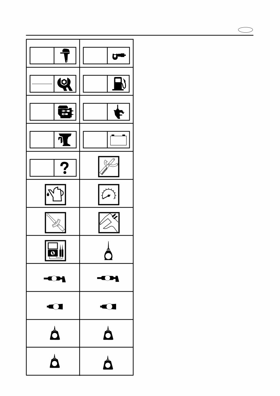
E A50001-1-4 SYMBOLS Symbols 1 to 9 are designed as thumb- tabs to indicate the content of a chapter. 1 General information 2 Specifications 3 Periodic inspection and adjustment 4 Fuel system 5 Power unit 6 Lower unit 7 Bracket unit 8 Electrical systems 9 Trouble-analysis Symbols 0 to E indicate specific data: 0 Special tool A Specified liquid B Specified engine speed C Specified torque D Specified measurement E Specified electrical value [Resistance (Ω), Voltage (V), Electric current (A)] Symbol F to H in an exploded diagram indicate the grade of lubricant and the loca- tion of the lubrication point: F Apply Yamaha 2-stroke outboard motor oil G Apply water resistant grease (Yamaha grease A, Yamaha marine grease) H Apply molybdenum disulfide oil Symbols I to N in an exploded diagram indicate the grade of the sealing or locking agent and the location of the application point: I Apply Gasket Maker J Apply Yamabond #4 (Yamaha bond number 4) K Apply LOCTITE No. 271 (Red LOCTITE) L Apply LOCTITE No. 242 (Blue LOCTITE) M Apply LOCTITE No. 572 N Apply silicon sealant 1 2 3 4 5 6 7 8 9 0 A B C D E F G H I J K L M N GEN INFO SPEC INSP ADJ FUEL POWR LOWR BRKT – + ELEC TRBL ANLS T R . . E A M GM 4 271 LT 242 LT 572 LT SS
Yamaha 20/25HP (F20/F25) Outboards OEM Service & Repair Manual
Models covered:
Yamaha F20AMH/S
Yamaha F20AMH/L
Yamaha F20AEH/S
Yamaha F20AEH/L
Yamaha F20AE/S
Yamaha F20AE/L
Yamaha F20AET/L
Yamaha F25AMH
Yamaha F25MH/S
Yamaha F25AMH
Yamaha F25MH/L
Yamaha F25AMH
Yamaha F25MH/X
Yamaha F25AEH
Yamaha F25EH/S
Yamaha F25AEH
Yamaha F25EH/L
Yamaha F25AEHT
Yamaha F25TH/L
Yamaha F25AE
Yamaha F25ER/S
Yamaha F25AE
Yamaha F25ER/L
Yamaha F25AET
Yamaha F25TR/L
The Yamaha 20/25HP (F20/F25) Outboards OEM Service & Repair Manual provides detailed technical guidance essential for the maintenance and repair of these outboard engine models. Developed by Yamaha, this manual includes comprehensive procedures, wiring diagrams, and precise specifications necessary for accurate and efficient servicing.
Designed for professional marine technicians and experienced boat owners, this manual covers a wide range of critical topics. It offers step-by-step instructions for engine diagnostics, fuel system maintenance, and electrical system troubleshooting. The manual ensures that all maintenance and repair tasks are performed to factory standards, preserving the performance and reliability of your Yamaha outboard.
Available in a convenient digital format, this manual allows for easy access on various devices, making it a practical resource both in the workshop and on the water. The Yamaha 20/25HP (F20/F25) Outboards OEM Service & Repair Manual is an indispensable tool for ensuring the longevity and optimal functionality of your outboard engine.
Printable: Yes Language: English Compatibility: Pretty much any electronic device, incl. PC & Mac computers, Android and Apple smartphones & tablet, etc. Requirements: Adobe Reader (free)
Recently Viewed
5,521,897Happy Clients
2,594,462eManuals
1,120,453Trusted Sellers
15Years in Business
Price:
Actual Price:
Yamaha 20/25HP (F20/F25) Outboards OEM Service & Repair Manual