



VF200
VF225
VF250
SUPPLEMENTARY
SERVICE MANUAL
6CB-28197-1P-1X LIT-18616-03-32
Preface
This Supplementary Service Manual has been prepared to introduce new service and new data
information for VF200, VF225, and VF250. For complete information on service procedures, it is
necessary to use this Supplementary Service Manual along with the following manual.
VF200, VF225, and VF250 SERVICE MANUAL: LIT-18616-03-21 (6CB-28197-1M-11)
Important information
Particularly important information is distinguished in this manual by the following notations:
The Safety Alert Symbol means ATTENTION! BECOME ALERT! YOUR SAFETY IS
INVOLVED!
A WARNING indicates a hazardous situation which, if not avoided, could result in death or
serious injury.
A NOTICE indicates special precautions that must be taken to avoid damages to the out-
board motor or other property.
TIP:
A TIP provides key information to make procedures easier or clearer.
VF200, VF225, VF250
SUPPLEMENTARY
SERVICE MANUAL
©2011 by Yamaha Motor Corporation, U.S.A.
1st Edition, June 2011
All rights reserved.
Any reprinting or unauthorized use
without the written permission of
Yamaha Motor Corporation, U.S.A.
is expressly prohibited.
Printed in U.S.A.
LIT-18616-03-32
Supplementary contents
General information
GEN
INFO
0
Specification
SPEC
1
Technical features and description
TECH
FEA
2
Rigging information
RIG
GING
3
Troubleshooting
TRBL
SHTG
4
Electrical system ELEC
5
Fuel system
FUEL
6
Power unit
POWR
7
Lower unit LOWR
8
Bracket unit
BRKT
9
Maintenance
MNT
10
Index
Appendix
A

General information
Safety while working................................................................. 1
Rotating part ................................................................................... 1
Hot part ........................................................................................... 1
Electric shock ................................................................................. 1
Propeller ......................................................................................... 1
Handling of gasoline ....................................................................... 1
Ventilation....................................................................................... 1
Self-protection ................................................................................ 2
Working with crane ......................................................................... 2
Handling of gas torch ..................................................................... 2
Part, lubricant, and sealant ............................................................. 2
Handling of sealant ......................................................................... 3
Special service tool ........................................................................ 3
Tightening torque ........................................................................... 3
Non-reusable part ........................................................................... 3
Disassembly and assembly ............................................................ 3
How to use this manual ................................................................ 4
Manual format ................................................................................ 4
Abbreviation ................................................................................... 5
Lubricant, sealant, and thread locking agent ......................... 6
Symbol ........................................................................................... 6
Special service tool........................................................................ 7
Specification
Model feature ................................................................................... 9
Model designation .......................................................................... 9
Serial number ................................................................................. 9
Model data ...................................................................................... 10
Dimension and weight .................................................................. 10
Performance ................................................................................. 10
Power unit .................................................................................... 10
Lower unit ..................................................................................... 11
Bracket unit .................................................................................. 11
Fuel and oil requirement ............................................................... 11
Battery requirement ...................................................................... 12
PTT fluid requirement ................................................................... 12
Electrical system technical data .............................................. 12
Fuel injection control system ........................................................ 12

Y-COP (optional) .......................................................................... 12
Lower unit technical data ........................................................... 12
Lower unit assembly..................................................................... 12
Bracket unit technical data ........................................................ 13
PTT system .................................................................................. 13
Specified tightening torque ....................................................... 13
Rigging information ...................................................................... 13
Electrical system .......................................................................... 13
Fuel system .................................................................................. 13
Power unit .................................................................................... 13
Lower unit ..................................................................................... 14
PTT unit ........................................................................................ 14
General tightening torque .......................................................... 15
Technical features and description
Electronic control system .......................................................... 16
Fail-safe control ............................................................................ 17
Y-COP (optional) ........................................................................... 17
Tilt limiter (optional) .................................................................... 19
Power unit system........................................................................ 20
Crankcase .................................................................................... 20
Cooling system ............................................................................. 21
Cooling diagram ........................................................................... 21
Rigging information
Uncrating procedure.................................................................... 23
Installing Y-COP (optional) ........................................................ 24
Registering the receiver ID to the ECM ........................................ 24
Installing the tilt limiter (optional) .................................................. 25
Setting the tilt limiter (optional) ..................................................... 29
Deactivating the tilt limiter (optional) ............................................ 30

System diagram ............................................................................ 31
Single outboard motor application ................................................ 31
Troubleshooting
YDIS .................................................................................................. 33
Trouble code table........................................................................ 33
Troubleshooting the power unit using the YDIS ........................... 33
Trouble code and checking step .................................................. 33
Electrical system
Wiring harness routing ............................................................... 34
Port ............................................................................................... 34
Starboard...................................................................................... 36
Top ............................................................................................... 40
Bottom cowling ............................................................................. 41
Fuel control unit and component ............................................ 43
Checking the low-pressure fuel pump and
high-pressure fuel pump............................................................... 43
Y-COP (optional) ........................................................................... 45
Checking Y-COP .......................................................................... 46
Checking the buzzer ..................................................................... 46
Checking the Y-COP main wiring harness ................................... 46
Checking the button cell battery ................................................... 47
PTT electrical system .................................................................. 48
Checking the tilt limiter (optional) ................................................. 48
Fuel system
Hose routing .................................................................................. 50
Cooling water hose....................................................................... 50
Vapor separator ............................................................................ 52
Removing the vapor separator ..................................................... 54
Installing the vapor separator ....................................................... 54

Power unit
Junction box .................................................................................. 55
Removing the Rectifier Regulator ................................................ 57
Removing the junction box ........................................................... 57
Installing the junction box ............................................................. 58
Installing the Rectifier Regulator .................................................. 58
Oil cooler and oil pump assembly ........................................... 60
Removing the oil cooler ................................................................ 63
Installing the oil cooler .................................................................. 63
Cylinder block sensor and switch ........................................... 64
Removing the cooling water cover ............................................... 67
Removing the thermostat ............................................................. 67
Checking the cooling water cover anode ..................................... 67
Installing the thermostat ............................................................... 67
Installing the cooling water cover ................................................. 68
Cylinder block ............................................................................... 69
Disassembling the cylinder block ................................................. 71
Assembling the cylinder block ...................................................... 72
Lower unit
Lower unit ....................................................................................... 76
Drive shaft and lower case ........................................................ 78
Disassembling the lower case ...................................................... 80
Assembling the drive shaft ........................................................... 80
Installing the lower unit ................................................................. 82
Shimming ........................................................................................ 83
Measuring the forward gear backlash and
reverse gear backlash before disassembly .................................. 83
Shimming ..................................................................................... 86
Shim location ................................................................................ 86
Measuring the forward gear backlash .......................................... 87
Measuring the reverse gear backlash .......................................... 87
Adjusting the reverse gear shim (T2) thickness ........................... 87
Reverse gear shim (T2) selection chart ....................................... 89

Bracket unit
PTT unit ........................................................................................... 91
Checking the hydraulic pressure .................................................. 91
PTT cylinder ................................................................................... 93
Bleeding the PTT unit ................................................................... 93
Maintenance
Outline ............................................................................................. 95
Maintenance chart 1 ..................................................................... 95
Maintenance chart 2 ..................................................................... 97
General periodic maintenance.................................................. 98
Checking the cooling water passage............................................ 98
Changing gear oil ......................................................................... 98
Appendix
Wiring diagram ............................................................................ 101
How to use the wiring diagram ................................................... 101
1
Safety while working
To prevent an accident or injury and to pro-
vide quality service, observe the following
safety procedures.
Rotating part
• Hands, feet, hair, jewelry, clothing, per-
sonal flotation device straps, and so on,
can become entangled with internal rotating
parts of the engine, resulting in serious
injury or death.
• Keep the top cowling installed whenever
possible. Do not remove or install the top
cowling when the engine is running.
• Only operate the engine with the top cowl-
ing removed according to the specific
instructions in the manual. Keep hands,
feet, hair, jewelry, clothing, personal flota-
tion device straps, and so on, away from
any exposed moving parts.
Hot part
During and after operation, engine parts are
hot enough to cause burns. Do not touch any
parts under the top cowling until the engine
has cooled.
Electric shock
Do not touch any electrical parts while start-
ing or operating the engine. Otherwise, shock
or electrocution could result.
Propeller
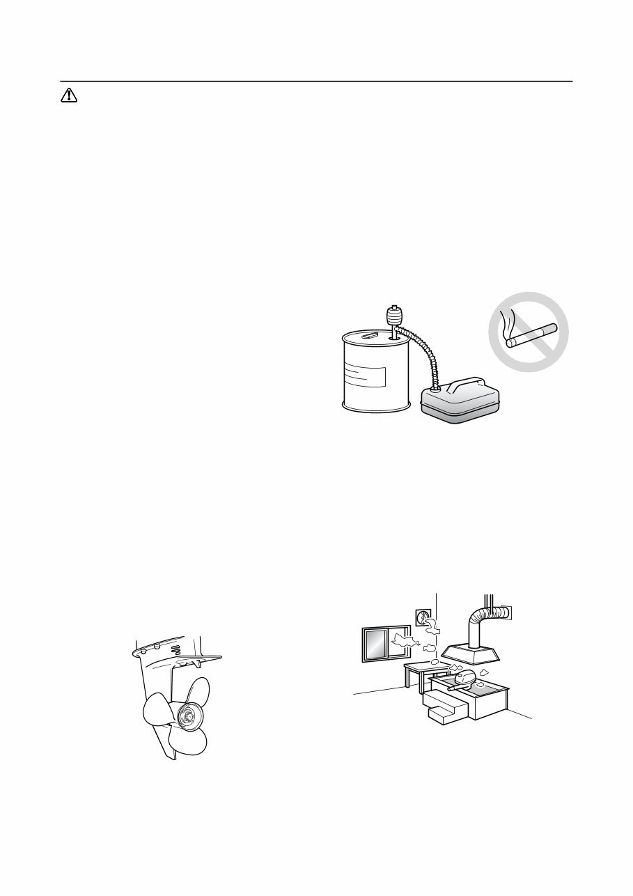
Do not hold the propeller with your hands
when loosening or tightening the propeller
nut.
Handling of gasoline
• Gasoline is highly flammable. Keep gaso-
line and all flammable products away from
heat, sparks, and open flames.
• Gasoline is poisonous and can cause injury
or death. Handle gasoline with care. Never
siphon gasoline by mouth. If you swallow
some gasoline, inhale a lot of gasoline
vapor, or get some gasoline in your eyes,
see your doctor immediately. If gasoline
spills on your skin, wash with soap and
water. If gasoline spills on your clothing,
change your clothes.
Ventilation
• Gasoline vapor and exhaust gas are
heavier than air and extremely poisonous.
If gasoline vapor or exhaust gas is inhaled
in large quantities, it may cause loss of con-
sciousness and death within a short time.
• When test running an engine indoors (for
example, in a water tank) make sure to do
so where adequate ventilation can be main-
tained.
General information
2
Self-protection
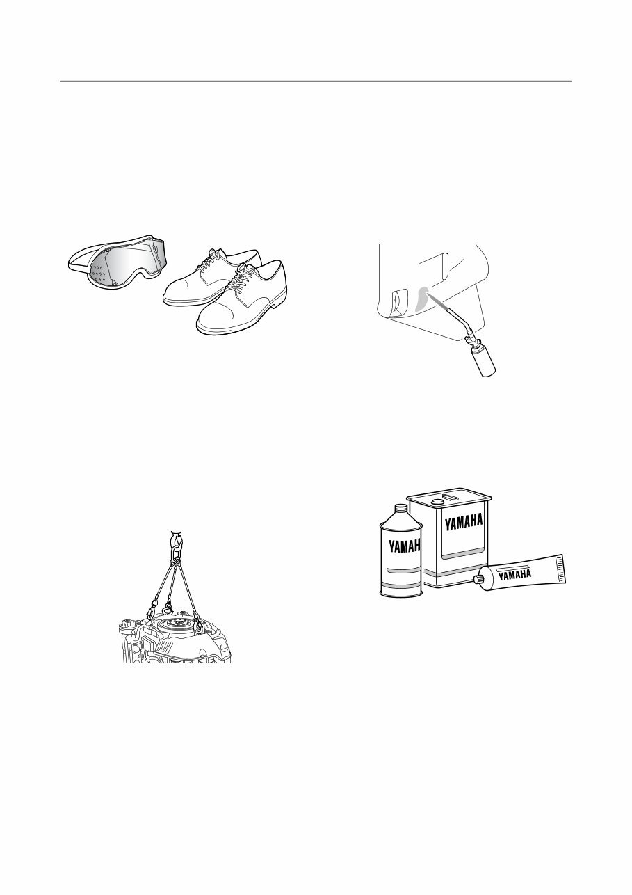
• Protect your eyes by wearing safety
glasses or safety goggles during all opera-
tions involving drilling and grinding, or when
using an air compressor.
• Protect your hands and feet by wearing
protective gloves and safety shoes when
necessary.
Working with crane
• Outboard motors weighing 18.0 kg (39.7 lb)
and over must be carried by a crane.
• Use the wire ropes of adequate strength,
and lift up the outboard motor using the
three point suspension.
• If the outboard motor does not have three
or more points to be suspended, support it
using additional ropes, or the like, so that
the outboard motor can be lifted and carried
in a stable manner.
Handling of gas torch
• Improper handling of a gas torch may result
in burns. For information on the proper han-
dling of the gas torch, see the operation
manual issued by the manufacturer.
• When using a gas torch, keep it away from
the gasoline and oil, to prevent a fire.
• Components become hot enough to cause
burns. Do not touch any hot components
directly.
Part, lubricant, and sealant
Use only genuine Yamaha parts, lubricants,
and sealants, or those recommended by
Yamaha, when servicing or repairing the out-
board motor.
You're Reading a Preview
What's Included?
 Lifetime Access
Fast Download Speeds
Online & Offline Access
Access PDF Contents & Bookmarks
Full Search Facility
Print one or all pages of your manual
$35.99
Yamaha VF200 outboard service repair manual. PID Range 6CDL-1000832 ~ Current Supplement for motors mfg June 2011 and newer Use
Viewed 79 Times Today

What's Included?
Lifetime Access
Fast Download Speeds
Online & Offline Access
Access PDF Contents & Bookmarks
Full Search Facility
Print one or all pages of your manual
$35.99

Secure transaction
What's Included?
Lifetime Access
Fast Download Speeds
Online & Offline Access
Access PDF Contents & Bookmarks
Full Search Facility
Print one or all pages of your manual
Description
This manual is a comprehensive guide covering all aspects of the Yamaha VF200 PID Range 6CDL-1000832 and newer outboard motors manufactured from June 2011 onwards. It is designed as a factory service manual, providing detailed information on disassembly, repair, assembly, and inspection procedures in a sequential, step-by-step format. The manual includes exploded diagrams before each disassembly section to facilitate easy identification of the correct procedures. It is a valuable resource for both professional mechanics and DIY enthusiasts. For optimal use, it is recommended to be used in conjunction with service manual LIT-18616-03-21R.


