

2006 Yamaha 15/20HP (F15/F20) Outboards OEM Service & Repair Manual
What's Included?
Fast Download Speeds
Online & Offline Access
Access PDF Contents & Bookmarks
Full Search Facility
Print one or all pages of your manual

F15
F20
SERVICE MANUAL
6AG-28197-1J-11 LIT-18616-02-96
*LIT186160296*
NOTICE
This manual has been prepared by Yamaha primarily for use by Yamaha dealers and their trained
mechanics when performing maintenance procedures and repairs to Yamaha equipment. It has
been written to suit the needs of persons who have a basic understanding of the mechanical and
electrical concepts and procedures inherent in the work, for without such knowledge attempted
repairs or service to the equipment could render it unsafe or unfit for use.
Because Yamaha has a policy of continuously improving its products, models may differ in detail
from the descriptions and illustrations given in this publication. Use only the latest edition of this
manual. Authorized Yamaha dealers are notified periodically of modifications and significant
changes in specifications and procedures, and these are incorporated in successive editions of this
manual.
Important information 1
Particularly important information is distinguished in this manual by the following notations:
The Safety Alert Symbol means ATTENTION! BECOME ALERT! YOUR SAFETY IS
INVOLVED!
WARNING
Failure to follow WARNING instructions could result in severe injury or death to the machine
operator, a bystander, or a person inspecting or repairing the outboard motor.
CAUTION:
A CAUTION indicates special precautions that must be taken to avoid damage to the out-
board motor.
NOTE:
A NOTE provides key information to make procedures easier or clearer.
F15, F20
SERVICE MANUAL
©2006 by Yamaha Motor Corporation, USA
1st Edition, November 2006
All rights reserved.
Any reprinting or unauthorized use
without the written permission of
Yamaha Motor Corporation, USA
is expressly prohibited.
Printed in USA
LIT-18616-02-96
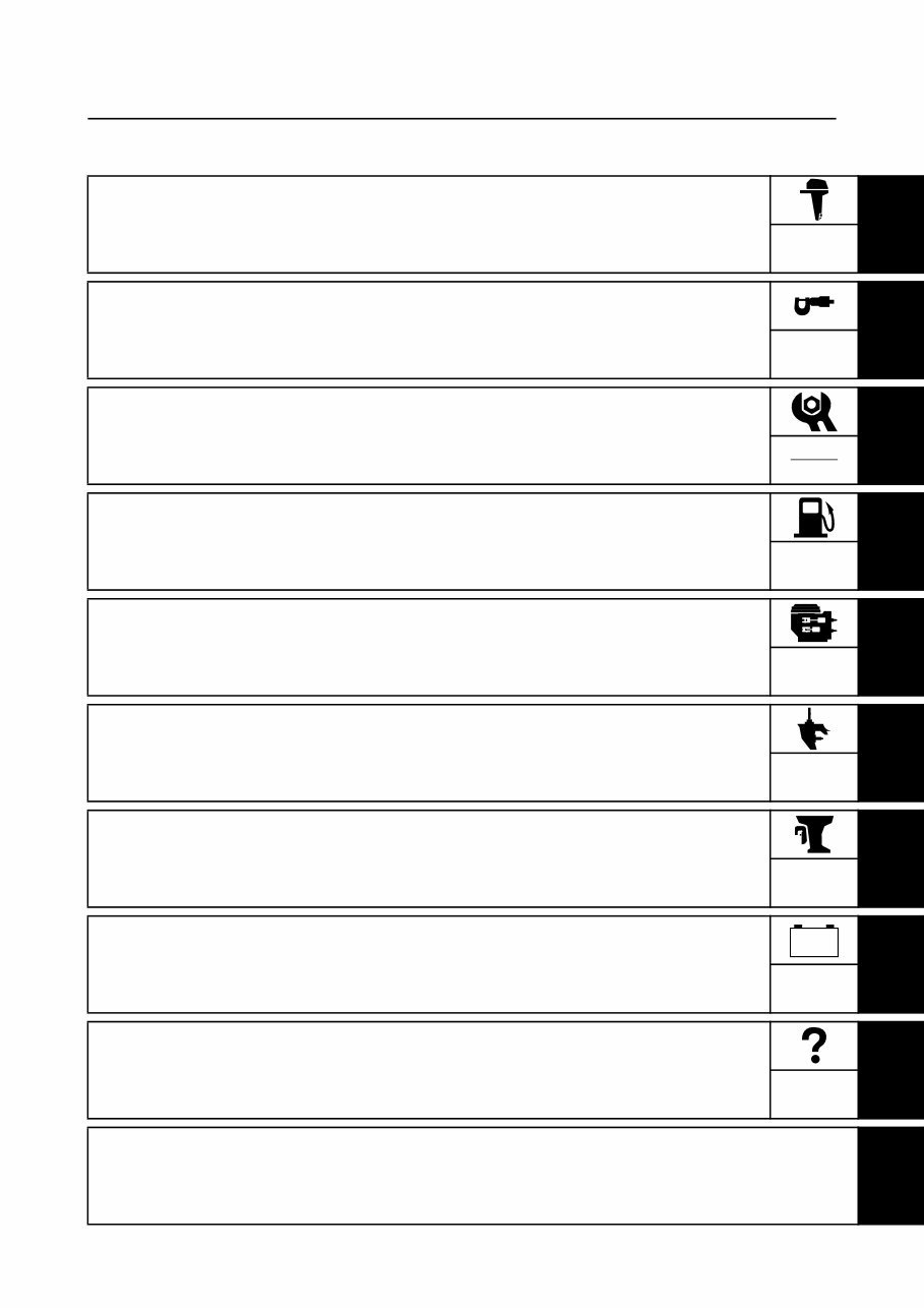
Contents
General information
1
GEN
INFO
Specification
2
SPEC
Periodic check and adjustment
3
CHK
ADJ
Fuel system
4
FUEL
Power unit
5
POWR
Lower unit
6
LOWR
Bracket unit
7
BRKT
Electrical system
8
ELEC
Troubleshooting
9
TRBL
SHTG
Index
– +


6AG1J11
GEN
INFO
1
2
3
4
5
6
7
8
9
General information
How to use this manual ................................................................................. 1-1
Manual format............................................................................................ 1-1
Symbol ....................................................................................................... 1-2
Abbreviation............................................................................................... 1-3
Sealant and locking agent table ................................................................ 1-3
Safety while working...................................................................................... 1-4
Fire prevention........................................................................................... 1-4
Ventilation .................................................................................................. 1-4
Self-protection ........................................................................................... 1-4
Part, lubricant, and sealant ........................................................................ 1-4
Good working practice ............................................................................... 1-5
Disassembly and assembly ....................................................................... 1-5
Identification ................................................................................................... 1-6
Model ......................................................................................................... 1-6
Serial number ............................................................................................ 1-6
Special service tool ....................................................................................... 1-7
Propeller selection ....................................................................................... 1-12
Propeller size ........................................................................................... 1-12
Selection .................................................................................................. 1-12
Predelivery check ........................................................................................ 1-12
Checking the outboard motor mounting height ........................................ 1-13
Removing the intake silencer protective covering ................................... 1-13
Checking the fuel system ........................................................................ 1-13
Checking the engine oil level ................................................................... 1-13
Checking the gear oil level ...................................................................... 1-14
Checking the battery (electric starter model) ........................................... 1-14
Setting the remote control cable (remote control model) ......................... 1-14
Checking the gear shift and throttle operation ......................................... 1-15
Checking the steering system ................................................................. 1-16
Checking the tilt system (manual tilt model) ............................................ 1-17
Checking the power tilt system (power tilt model) ................................... 1-17
Checking the engine start switch and engine stop lanyard switch .......... 1-18
Checking the cooling water pilot hole ...................................................... 1-18
Test run ................................................................................................... 1-19
Break-in ................................................................................................... 1-19
After test run ............................................................................................ 1-19
Precaution when transporting or storing the outboard motor .................. 1-19
GEN
INFO
General information
1-1 6AG1J11
How to use this manual 1
Manual format 1
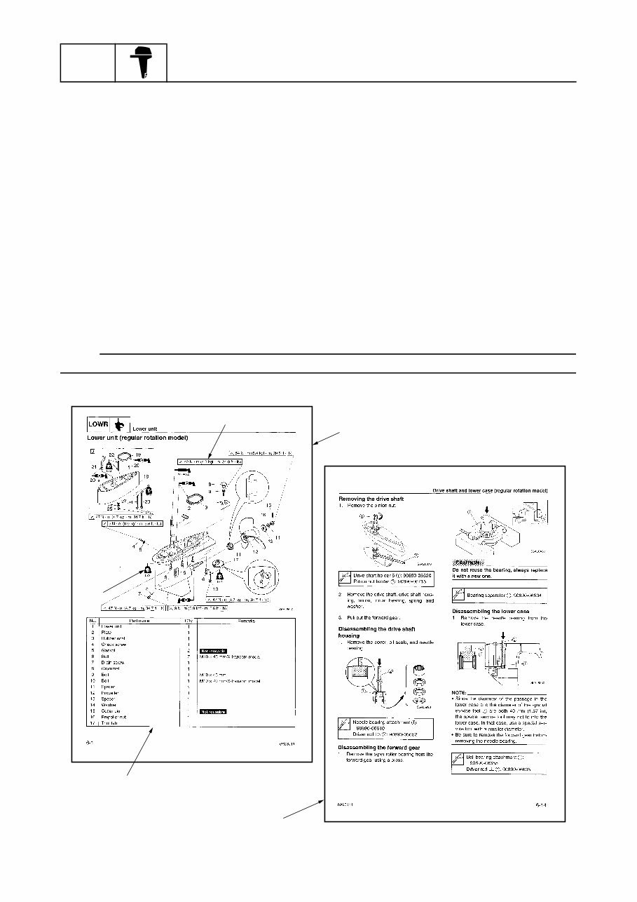
The format of this manual has been designed to make service procedures clear and easy to under-
stand. Use the information below as a guide for effective and quality service.
• Parts are shown and detailed in an exploded diagram and are listed in the component list (see 1
in the figure below for an example page).
• The component list consists of part names and quantities, as well as bolt and screw dimensions
(see 2 in the figure below).
• Symbols are used to indicate important aspects of a procedure, such as the grade of lubricant and
lubrication point (see 3 in the figure below).
• Tightening torque specifications are provided in the exploded diagrams (see 4 in the figure below
for an example), and in the related detailed instructions. Some torque specifications are listed in
stages as torque figures or angles in degrees.
• Separate procedures and illustrations are used to explain the details of removal, checking, and
installation where necessary (see 5 in the figure below for an example page).
NOTE:
For troubleshooting procedures, see Chapter 9, “Troubleshooting.”
5
2
3
4
1
6AG1J11 1-2
1
2
3
4
5
6
7
8
9
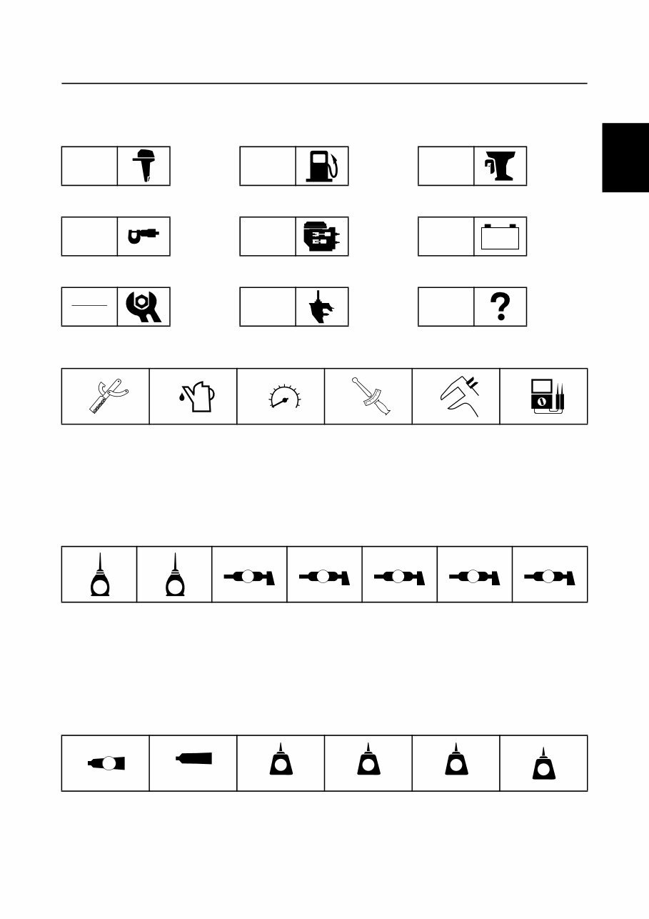
Symbol 1
The symbols below are designed to indicate the content of a chapter.
General information
Specification
Periodic check and adjustment
Fuel system
Power unit
Lower unit
Bracket unit
Electrical system
Troubleshooting
GEN
INFO
SPEC
CHK
ADJ
FUEL
POWR
LOWR
BRKT
ELEC
TRBL
SHTG
– +
Symbols 1 to 6 indicate specific data.
1 Special service tool
2 Specified oil or fluid
3 Specified engine speed
4 Specified tightening torque
5 Specified measurement
6 Specified electrical value
(resistance, voltage, electric current)
Symbols 7 to C in an exploded diagram or illustration indicate the grade of lubricant and the lubri-
cation point.
7 Apply 4-stroke motor oil
8 Apply gear oil
9 Apply water resistant grease (Yamaha grease A)
0 Apply molybdenum disulfide grease
A Apply corrosion resistant grease
(Yamaha grease D)
B Apply low temperature resistant grease
(Yamaha grease C)
C Apply injector grease
Symbols D to I in an exploded diagram or illustration indicate the type of sealant or locking agent
and the application point.
D Apply Gasket Maker
E Apply ThreeBond 1104J
F Apply LOCTITE 271 (red)
G Apply LOCTITE 242 (blue)
H Apply LOCTITE 572
I Apply silicone sealant
1 2 3 4 5 6
T
R
.
.
7 8 9 0 A B C
E G
A M D C I
D E F G H I
GM
1104J
271
LT
242
LT
572
LT
SS
How to use this manual
GEN
INFO
General information
1-3 6AG1J11
Abbreviation 1
The following abbreviations are used in this service manual.
Sealant and locking agent table 1
The following table contains sealants, locking agents, and greases used in this service manual that
are not listed on page 1-2.
Abbreviation Description
ABYC American Boat and Yacht Council
API American Petroleum Institute
BOW Bow end
CCA Cold Cranking Ampere
CDI Capacitor Discharge Ignition
EX Exhaust
IN Intake
MCA Marine Cranking Ampere
PORT Port side
RC Reserve Capacity
SAE Society of Automotive Engineers
STBD Starboard side
TDC Top Dead Center
WD Wiring Diagram
Symbol Name Application Manufacturer
LOCTITE 518 Sealant Henkel
S518
6AG1J11 1-4
1
2
3
4
5
6
7
8
9
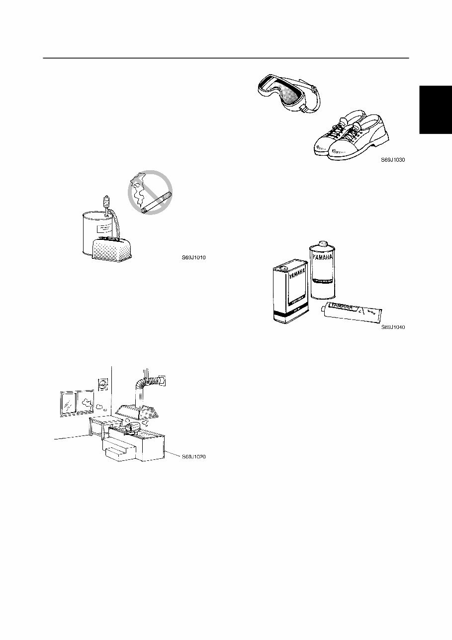
Safety while working 1
To prevent an accident or injury and to
ensure quality service, follow the safety pro-
cedures provided below.
Fire prevention 1
Gasoline is highly flammable.
Keep gasoline and all flammable products
away from heat, sparks, and open flames.
Ventilation 1
Gasoline vapor and exhaust gas are heavier
than air and extremely poisonous. If inhaled
in large quantities, they may cause loss of
consciousness and death within a short time.
When test running an engine indoors (e.g., in
a water tank) be sure to do so where ade-
quate ventilation can be maintained.
Self-protection 1
Protect your eyes by wearing safety glasses
or safety goggles during all operations involv-
ing drilling and grinding, or when using an air
compressor.
Protect your hands and feet by wearing pro-
tective gloves and safety shoes when neces-
sary.
Part, lubricant, and sealant 1
Use only genuine Yamaha parts, lubricants,
and sealants or those recommended by
Yamaha, when servicing or repairing the out-
board motor.
Under normal conditions, the lubricants men-
tioned in this manual should not harm or be
hazardous to your skin. However, you should
follow these precautions to minimize any risk
when working with lubricants.
1. Maintain good standards of personal and
industrial hygiene.
2. Change and wash clothing as soon as
possible if soiled with lubricants.
3. Avoid contact with skin. Do not, for
example, place a soiled rag in your
pocket.
4. Wash hands and any other part of the
body thoroughly with soap and hot water
after contact with a lubricant or lubricant
soiled clothing has been made.
5. To protect your skin, apply a protective
cream to your hands before working on
the outboard motor.
How to use this manual / Safety while working
GEN
INFO
General information
1-5 6AG1J11
6. Keep a supply of clean, lint-free cloths for
wiping up spills, etc.
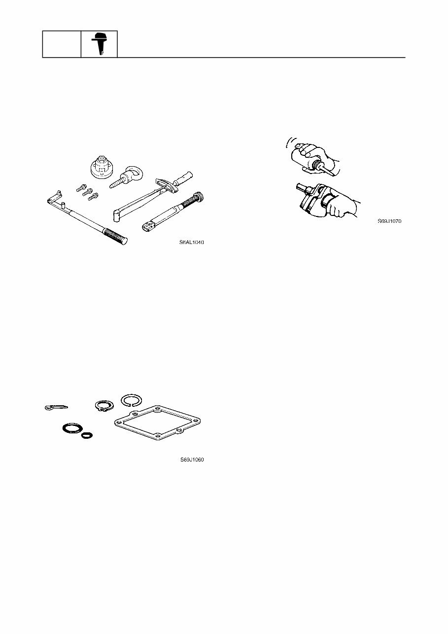
Good working practice 1
Special service tool
Use the recommended special service tools
to protect parts from damage. Use the right
tool in the right manner—do not improvise.
Tightening torque
Follow the tightening torque specifications
provided throughout the manual. When tight-
ening nuts, bolts, and screws, tighten the
large sizes first, and tighten fasteners starting
in the center and moving outward.
Non-reusable part
Always use new gaskets, seals, O-rings, cot-
ter pins, circlips, etc., when installing or
assembling parts.
Disassembly and assembly 1
1. Use compressed air to remove dust and
dirt during disassembly.
2. Apply engine oil to the contact surfaces
of moving parts before assembly.
3. Install bearings with the manufacture
identification mark in the direction indi-
cated in the installation procedure. In
addition, be sure to lubricate the bearings
liberally.
4. Apply a thin coat of water resistant
grease to the lip and periphery of an oil
seal before installation.
5. Check that moving parts operate nor-
mally after assembly.
You're Reading a Preview
What's Included?
Fast Download Speeds
Online & Offline Access
Access PDF Contents & Bookmarks
Full Search Facility
Print one or all pages of your manual
$35.99
Viewed 74 Times Today


Secure transaction
What's Included?
Fast Download Speeds
Online & Offline Access
Access PDF Contents & Bookmarks
Full Search Facility
Print one or all pages of your manual
$35.99
This manual is a comprehensive guide covering the 2006 Yamaha 15/20HP (F15/F20) Outboards. It is designed to provide mechanics with an easy-to-read reference for all disassembly, repair, assembly, and inspection operations. Each chapter features exploded diagrams prior to the disassembly sections to simplify the identification of correct procedures.
- Applicable to both F15 and F20 motor models
- Detailed technical procedures for OEM service and repair
- Fully bookmarked and searchable for quick reference
- Comprehensive coverage of all aspects of the motor


