E HOW TO USE THIS MANUAL MANUAL FORMAT All of the procedures in this manual are organized in a sequential, step-by-step format. The information has been compiled to provide the mechanic with an easy to read, handy refer- ence that contains comprehensive explanations of all disassembly, repair, assembly, and inspection operations. For instance, the condition of a faulty component will precede an arrow symbol and the course of action required will follow the symbol. • Bearings Pitting/scratches → Replace. To assist you in finding your way through this manual, the section title and major heading is given at the top of every page. MODEL INDICATION Multiple models are mentioned in this manual and their model indications are noted as fol- lows. ILLUSTRATIONS The illustrations within this service manual represent all of the designated models. CROSS REFERENCES The cross references have been kept to a minimum. Cross references will direct you to the appropriate section or chapter. Model name 150FETO 150GETO USA and Canada name 150TR V150TR Indication 150FETO 150GETO
E IMPORTANT INFORMATION In this Service Manual particularly important information is distinguished in the following ways. The Safety Alert Symbol means ATTENTION! BECOME ALERT! YOUR SAFETY IS INVOLVED! WARNING Failure to follow WARNING instructions could result in severe injury or death to the machine operator, a bystander, or a person inspecting or repairing the outboard motor. CAUTION: A CAUTION indicates special precautions that must be taken to avoid damage to the out- board motor. NOTE: A NOTE provides key information to make procedures easier or clearer. SPECIFICATIONS These are given in bold type at each procedure. It is not necessary to leave the section deal- ing with the procedure in order to look up the specifications. It is important to note the differences in specifications of models. When a procedure relates to more than one model, the main differences in specifications will be shown in a table similar to the following. Model name 150FETO 150GETO USA and Canada name 150TR V150TR Lubrication system Oil injection Oil injection
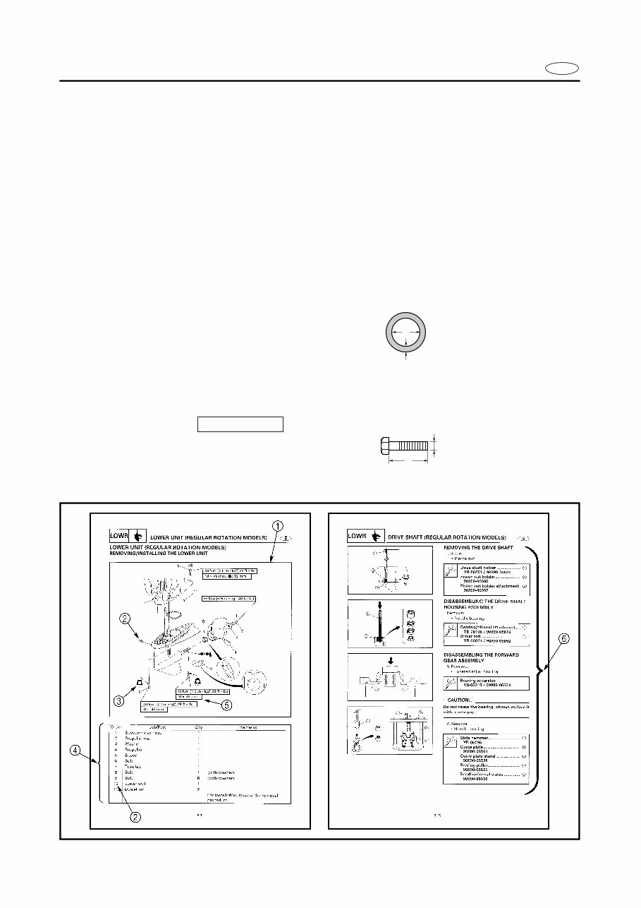
E HOW TO USE THIS MANUAL 1 The main points regarding removing/installing and disassembling/assembling procedures are shown in the exploded views. 2 The numbers in the exploded views indicate the required sequence of the procedure and should be observed accordingly. 3 Symbols are used in the exploded views to indicate important aspects of the procedure. A list of meanings for these symbols is provided on the following page. 4 It is important to refer to the job instruction charts at the same time as the exploded views. These charts list the sequence that the procedures should be carried out in, as well as pro- viding explanations on part names, quantities, dimensions and important points relating to each relevant task. Example: O-ring size 39.5 × 2.5 mm: inside diameter (D) × ring diameter (d) 5 In addition to tightening torques, the dimensions of the bolts and screws are also men- tioned. Example: Bolt and screw size : bolt and screw diameter (D) × length (L) 6 In addition to the exploded views and job instruction charts, this manual provides individ- ual illustrations when further explanations are required to explain the relevant procedure. d D 10 × 25 mm D L
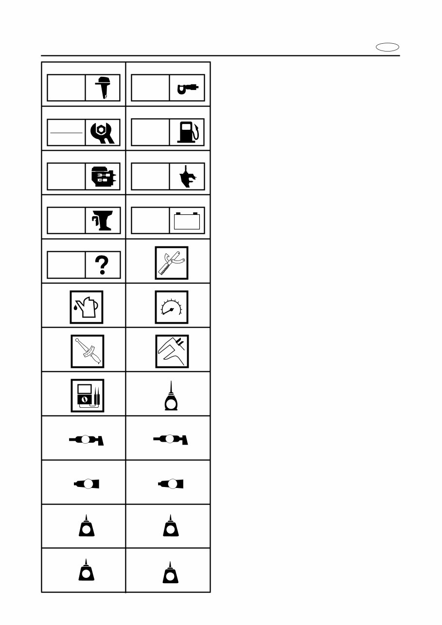
E SYMBOLS Symbols 1 to 9 are designed as thumb- tabs to indicate the content of a chapter. 1 General information 2 Specifications 3 Periodic inspections and adjustments 4 Fuel system 5 Power unit 6 Lower unit 7 Bracket unit 8 Electrical systems 9 Trouble analysis Symbols 0 to E indicate specific data. 0 Special tool A Specified liquid B Specified engine speed C Specified torque D Specified measurement E Specified electrical value [Resistance (Ω), Voltage (V), Electric current (A)] Symbol F to H in an exploded diagram indicate the grade of lubricant and the loca- tion of the lubrication point. F Apply Yamaha 2-stroke outboard motor oil (TC-W3) G Apply water resistant grease (Yamaha grease A, Yamaha marine grease) H Apply molybdenum disulfide oil Symbols I to N in an exploded diagram indicate the grade of the sealing or locking agent and the location of the application point. I Apply Gasket Maker ® J Apply Yamabond #4 (Yamaha bond number 4) K Apply LOCTITE ® No. 271 (Red LOCTITE) L Apply LOCTITE ® No. 242 (Blue LOCTITE) M Apply LOCTITE ® No. 572 N Apply silicon sealant 1 2 3 4 5 6 7 8 9 0 A B C D E F G H I J K L M N GEN INFO SPEC INSP ADJ FUEL POWR LOWR BRKT – + ELEC TRBL ANLS T R . . E A M GM 4 271 LT 242 LT 572 LT SS
E CONTENTS GENERAL INFORMATION 1 SPECIFICATIONS 2 SPEC PERIODIC INSPECTIONS AND ADJUSTMENTS 3 FUEL SYSTEM 4 FUEL POWER UNIT 5 POWR LOWER UNIT 6 LOWR BRACKET UNIT 7 BRKT ELECTRICAL SYSTEMS 8 ELEC TROUBLE ANALYSIS 9 GEN INFO INSP ADJ – + TRBL ANLS
E 1 2 3 4 5 6 7 8 9 GEN INFO CHAPTER 1 GENERAL INFORMATION IDENTIFICATION ............................................................................................ 1-1 SERIAL NUMBER ..................................................................................... 1-1 STARTING SERIAL NUMBERS ............................................................... 1-1 SAFETY WHILE WORKING ............................................................................ 1-2 FIRE PREVENTION ................................................................................... 1-2 VENTILATION........................................................................................... 1-2 SELF-PROTECTION.................................................................................. 1-2 OILS, GREASES AND SEALING FLUIDS................................................ 1-2 GOOD WORKING PRACTICES ................................................................ 1-3 DISASSEMBLY AND ASSEMBLY ........................................................... 1-4 SPECIAL TOOLS ............................................................................................. 1-5 MEASURING ............................................................................................ 1-5 REMOVING AND INSTALLING ............................................................... 1-7
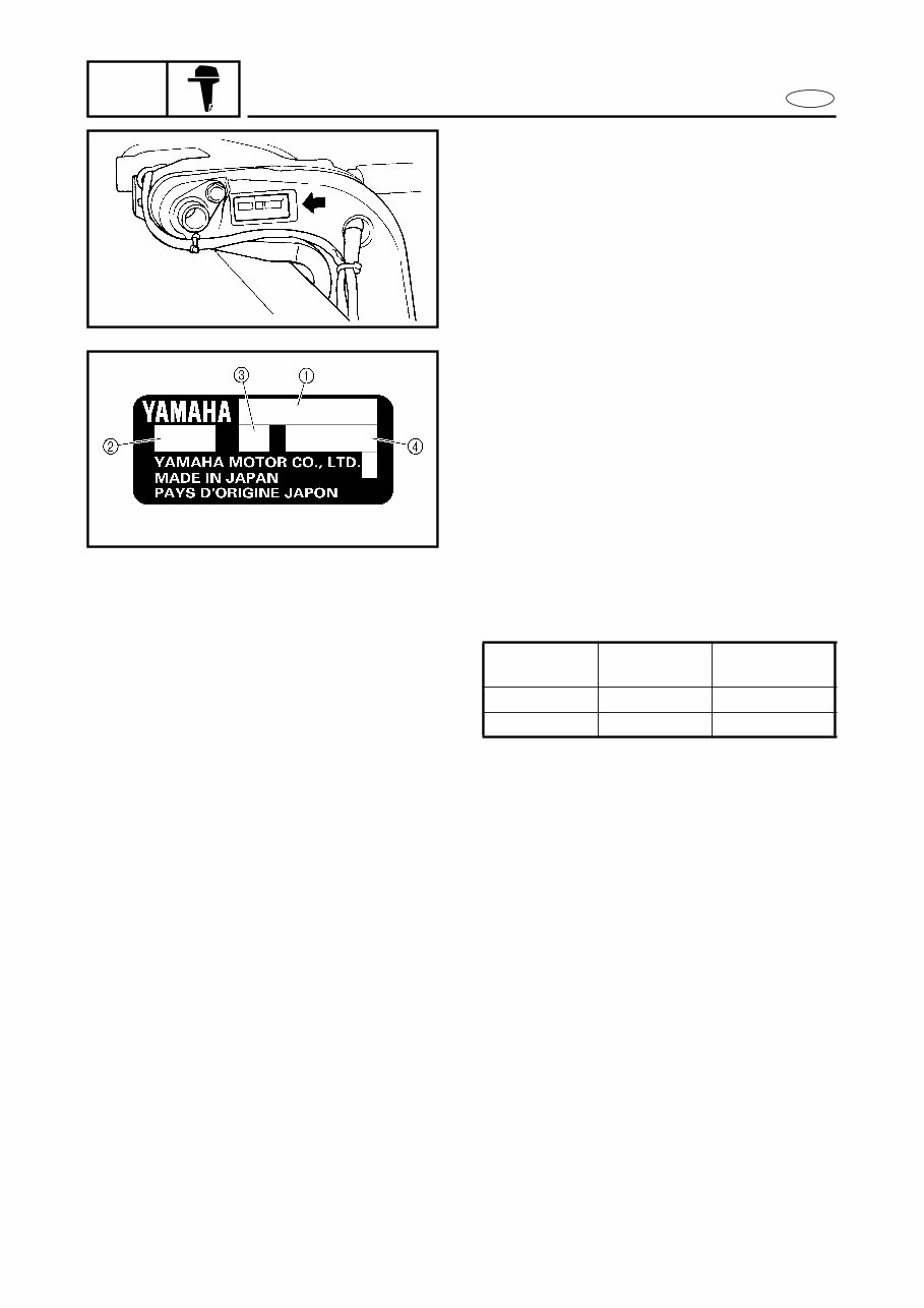
1-1 GEN INFO E IDENTIFICATION IDENTIFICATION 1 SERIAL NUMBER The outboard motor serial number is stamped on a label attached to the port clamp bracket. 1 Model name 2 Approved model code 3 Transom height 4 Serial number S67H1010 1020 STARTING SERIAL NUMBERS The starting serial number blocks are as fol- lows: Model name Approved model code Starting serial No. 150TR 6G4 X: 1006970 - V150TR 6J9 L: 1003950 -
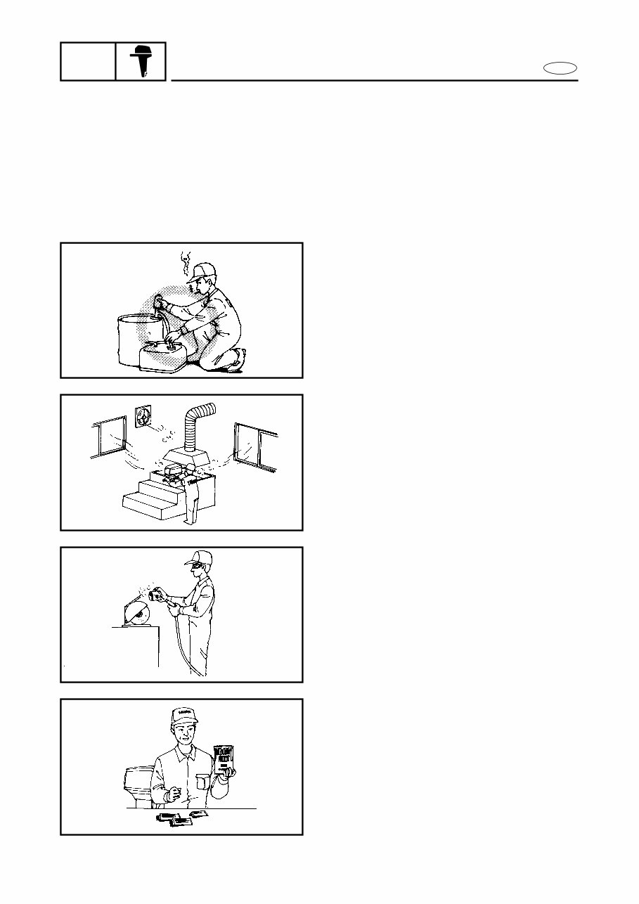
1-2 GEN INFO E SAFETY WHILE WORKING SAFETY WHILE WORKING 1 The procedures given in this manual are those recommended by Yamaha to be fol- lowed by Yamaha dealers and their mechanics. FIRE PREVENTION Gasoline (petrol) is highly flammable. Petroleum vapor is explosive if ignited. Do not smoke while handling gasoline and keep it away from heat, sparks and open flames. 1030 VENTILATION Petroleum vapor is heavier than air and is deadly if inhaled in large quantities. Engine exhaust gases are harmful to breathe. When test-running an engine indoors, maintain good ventilation. 1040 SELF-PROTECTION Protect your eyes with suitable safety glasses or safety goggles, when grinding or when doing any operation which may cause particles to fly off. Protect hands and feet by wearing safety gloves or protective shoes if appropriate to the work you are doing. 1050 OILS, GREASES AND SEALING FLUIDS Use only genuine Yamaha oils, greases and sealing fluids or those recommended by Yamaha. 1060
The 2006 Yamaha 150HP 2-Stroke Outboards OEM Service & Repair Manual is the official workshop guide for maintaining and servicing the Yamaha 150TR and V150TR models. Built for serious mechanical work, this manual is a reliable reference for both seasoned marine technicians and hands-on boat owners who prefer doing the job themselves.
Inside, you'll find full procedures for powerhead disassembly, lower unit service, bracket unit inspection, and fuel system troubleshooting. It also covers routine maintenance tasks like timing checks, carb adjustments, and periodic inspection schedules. Factory specifications, torque values, and diagnostic procedures are all laid out clearly.
Content overview:
General information
Technical specifications and reference data
Periodic inspections and adjustment procedures
Fuel system servicing and troubleshooting
Power unit disassembly, inspection, and repair
Lower unit maintenance and overhaul
Bracket unit servicing and structural checks
Electrical systems testing, wiring, and repair
Trouble analysis and diagnostic procedures for common issues
Whether you're rebuilding the power unit or just chasing down a hard-start issue, this manual gives you the structure and technical detail you need to get it done right. A solid choice for anyone maintaining a Yamaha 150HP 2-stroke outboard.
Printable: Yes Language: English Compatibility: Pretty much any electronic device, incl. PC & Mac computers, Android and Apple smartphones & tablet, etc. Requirements: Adobe Reader (free)