

1987-1989 Yamaha 150/175/200HP 2-Stroke Outboard Service & Repair Manual
What's Included?
Fast Download Speeds
Online & Offline Access
Access PDF Contents & Bookmarks
Full Search Facility
Print one or all pages of your manual

1987 - 1989
OUTBOARD
SERVICE MANUAL
Model : 200ETLF, 200ETLG, 200ETLH,
200ETXF, 200ETXG, 200ETXH, L200ETXG,
PROV150F, PROV150G, PROV150LH,
V6EXCELLF
6J9281972100 *6J9281972100*
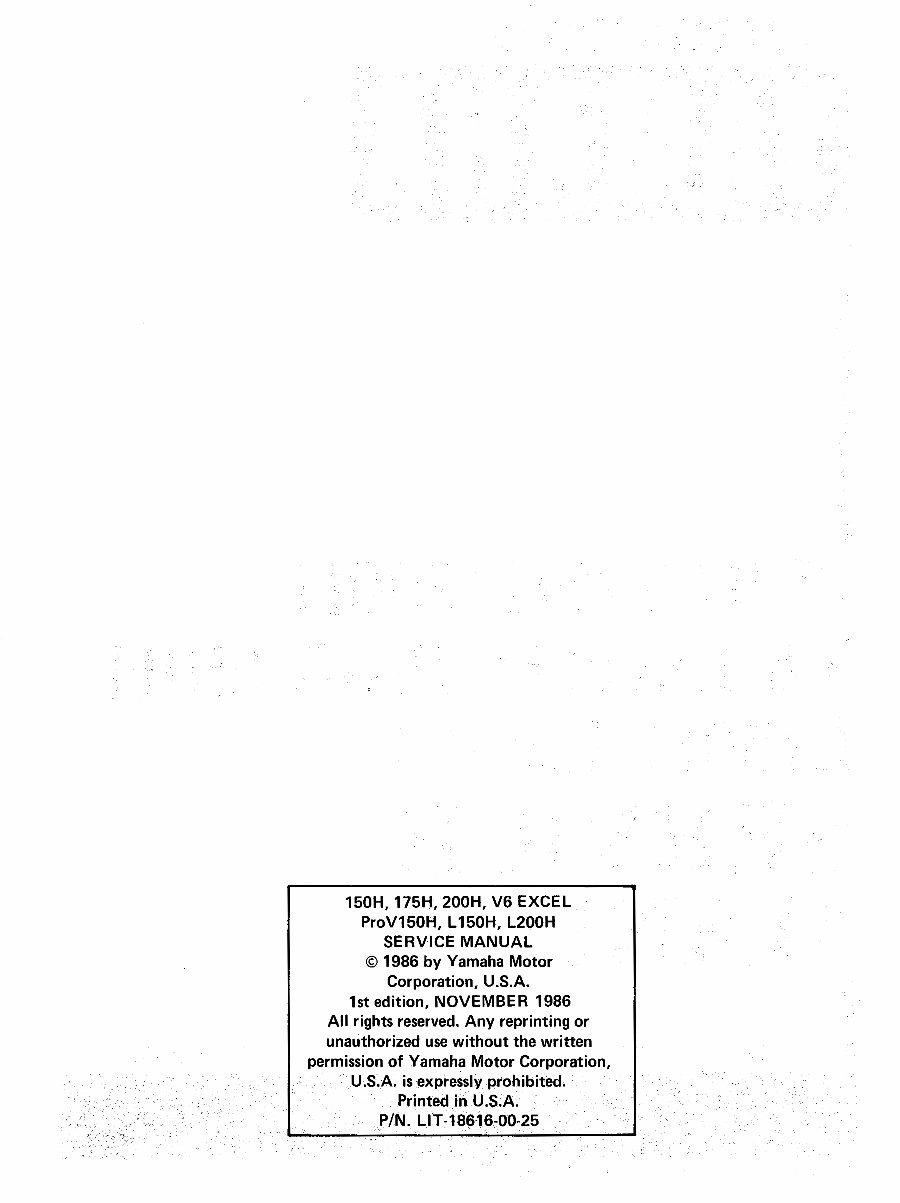
150H, 175H, 200H, V6 EXCEL
ProV150H, L150H, L200H
SERVICE MANUAL
© 1986 by Yamaha Motor
Corporation, U.S.A.
1st edition, NOVEMBER 1986
All rights reserved. Any reprinting or
unauthorized use without the written
permissionof Yamaha Motor Corporation,
U.S.A. isexpresslyprohibited.
Printed in U.S.A.
P/N. LIT-18616-00-25

EXTERNAL VIEW
V6 Excel
150HP,175HP,200HP
_!°°'
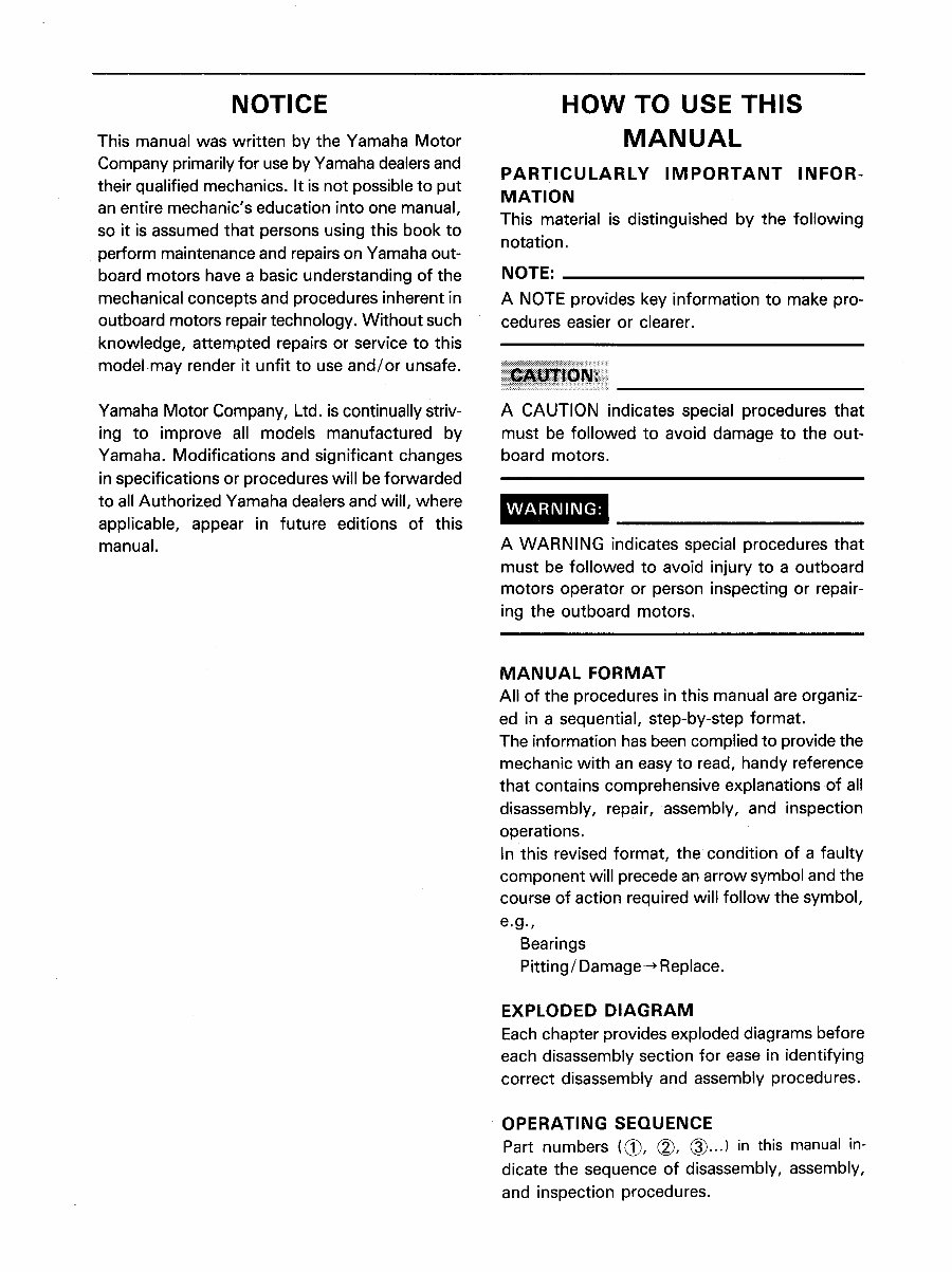
NOTICE HOW TO USE THIS
This manual was written by the Yamaha Motor MAN UAL
Company primarily for use byYamaha dealersand
PARTICULARLY IMPORTANT INFOR-
their qualifiedmechanics. It is not possibleto put MATION
an entire mechanic's education into one manual,
This material is distinguished by the following
so it is assumed that persons using this book to
notation.
perform maintenance and repairs on Yamaha out-
board motors have a basic understanding of the NOTE:
mechanical concepts and procedures inherent in A NOTE provides key information to make pro-
outboard motors repair technology. Without such cedures easier or clearer.
knowledge, attempted repairs or service to this
modelmay render it unfit to use and/or unsafe. !i!!!iii_i_ii_i_iiiiiiiiii:iil
Yamaha Motor Company, Ltd. is continually striv- A CAUTION indicates special procedures that
ing to improve all models manufactured by must be followed to avoid damage to the out-
Yamaha. Modifications and significant changes board motors.
in specifications or procedures will be forwarded
to all Authorized Yamaha dealers and will, where
WARNIN( :
applicable, appear in future editions of this
manual. A WARNING indicates special procedures that
must be followed to avoid injury to a outboard
motors operator or person inspecting or repair-
ing the outboard motors.
MANUAL FORMAT
All of the procedures in this manual are organiz-
ed in a sequential, step-by-step format.
The information has been complied to provide the
mechanic with an easy to read, handy reference
that contains comprehensive explanations of all
disassembly, repair, assembly, and inspection
operations.
In this revised format, the condition of a faulty
component will precede an arrow symbol and the
course of action required will follow the symbol,
e.g.,
Bearings
Pitting/Damage-, Replace.
EXPLODED DIAGRAM
Each chapter provides exploded diagrams before
each disassembly section for ease in identifying
correct disassembly and assembly procedures.
OPERATING SEQUENCE
Part numbers ((_), (_, (_...)in this manual in-
dicate the sequence of disassembly, assembly,
and inspection procedures.
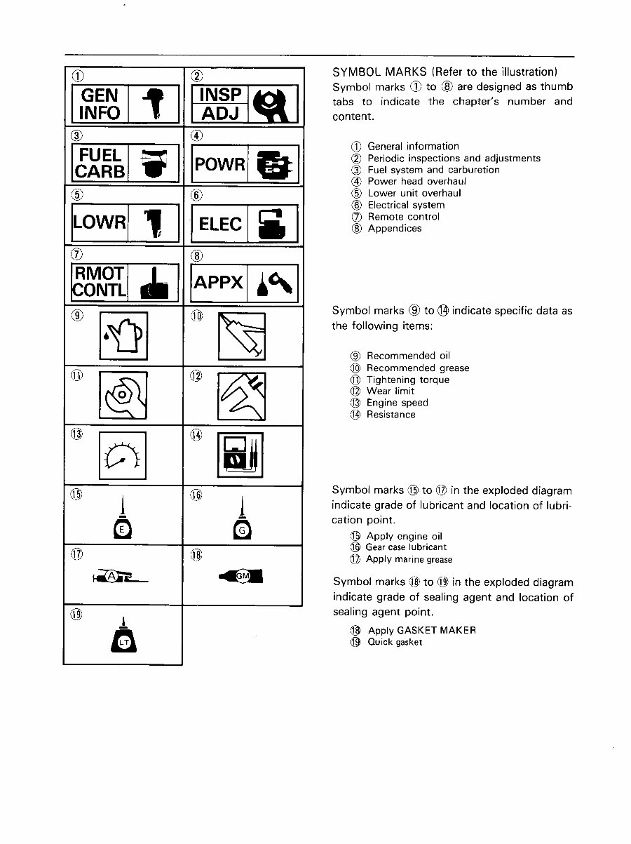
(_ (_ SYMBOL MARKS (Refer to the illustration)
r-e Symbol marks @ to (_ are designed as thumb
EN tabs to indicate the chapter's number and
_ {_ AL_..._ i _i content.
_ [e_wa (_ General information
(_) Periodic inspections and adjustments
(_) Fuel system and carburetion
@ Power head overhaul
(_ (_ ® Lower unit overhaul
[L I 1_: i I [ _ ® Electricalsystem
(_ Remote control
OWR ELEC ® Appendices
®
RMOTI
CO,T, ,I. +='1
(_ Symbol marks _ to (_ indicate specific data as
® [8_) _ the following items:
® Recommended oil
@ @ (_ Recommended grease
]_ i_ (_ Zighteningtorque
(_ Wear limit
@ Engine speed
(_) Resistance
@ @ J Symbol marks @ to @ in the exploded diagram
j | indicate of lubricant and location
grade
of lubri-
,IE
Q cation point.
(_ Apply engine oil
(_ Gear caselubricant
@ @ (_ Apply marine grease
_m,_ _ Symbol marks @ to (_ in the exploded diagram
indicate grade of sealing agent and location of
(_) sealing agent point.
@ Apply GASKET MAKER
@ Quick gasket
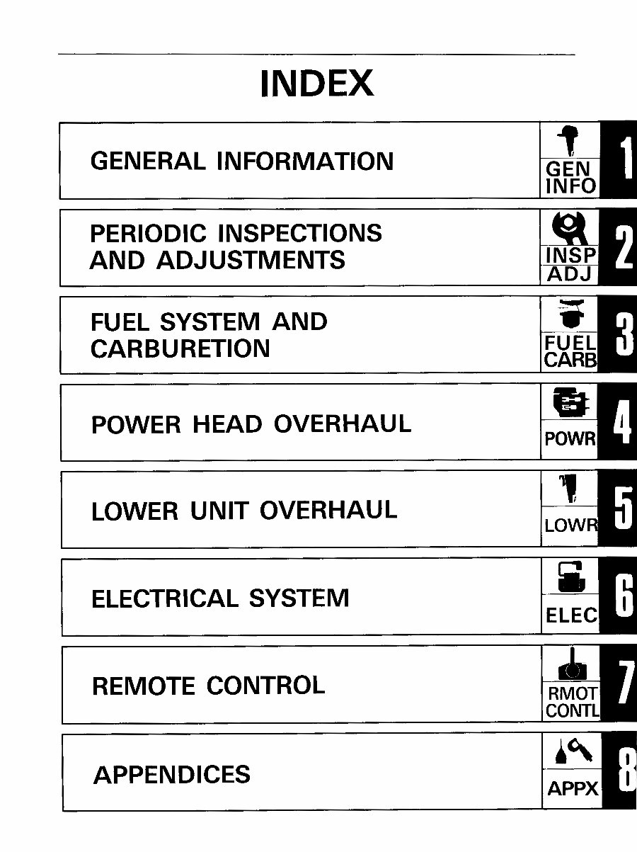
INDEX
GENERAL INFORMATION GEN
INFO
PERIODIC INSPECTIONS
AND ADJUSTMENTS INSP
ADJ
FUEL SYSTEM AND
CARBURETION FUEL
POWER HEAD OVERHAUL _:
LOWER UNIT OVERHAUL '_
ELECTRICAL SYSTEM
i .,I.-
REMOTE CONTROL RMOT
APPENDICES APPX

I GEN
,.o111' [
CHAPTER1
GENERAL INFORMATION
OUTBOARD MOTOR IDENTIFICATION ...................................... 1- 1
MODEL AND SERIAL NUMBER .......................................... 1- 1
ENGINE SERIAL NUMBER .............................................. 1- 1
IMPORTANT INFORMATION .............................................. 1-2
GASKET AND SEALS .................................................. 1- 2
CIRCLIPS ............................................................ 1- 2
LOCK WASHERS AND COTTER PINS .................................... 1- 2
BEARINGS AND OI L SEALS ............................................ 1- 2
TECHNICAL FEATURES .................................................. 1- 3
GENERAL .......................................................... 1- 3
ELECTRICAL ........................................................ 1- 6
POWER TRIM AND TILT ............................................... 1-10
OIL INJECTION SYSTEM .............................................. 1-15
OVERHEAT AND OIL LEVELWARNING SYSTEM .......................... 1-21
YAMAHA MICRO-COMPUTER IGNITION SYSTEM (Y.M.I.S.) (V6 Excel) ........ 1-25
FUNCTIONS OF Y.M.I.S ................................................. 1-28
Y.M.I.S. OPERATION NOTES ............................................ 1-35
SWITCH PANEL DESIGNED FOR TWIN-ENGINE MOUNT .................... 1-36
LOWER UNIT ............................................................ 1-42
CONSTRUCTION ...................................................... 1-42
SHIFT MECHANISM .................................................. 1-44
PROPELLER AND PROPELLER SELECTION .................................. 1-48
FUNCTION OF THE PROPELLER ........................................ 1-48
MOVEMENT OF THE PROPELLER IN THE WATER .......................... 1-48
PROPELLER PITCH .................................................... 1-49
PROPELLER SELECTION .............................................. 1-50
HIGH PERFORMANCE PROPELLER ...................................... 1-52
COOLING SYSTEM ...................................................... 1-53
SPECIAL TOOLS ........................................................ 1-55
FOR TUNE-UP ........................................................ 1-55
FOR ENGINE SERVICE ................................................ 1-56
FOR LOWER UNIT SERVICE ............................................ 1-58
FOR LOWER UNIT SERVICE (L200, L150) ................................ 1-62
FOR POWER TRIM AND TILT .......................................... 1-63
FOR ELECTRICAL COMPONENTS ....................................... 1-63
FOR ELECTRICAL COMPONENTS (V6 Excel) .............................. 1-64
FOR RIGGING ........................................................ 1-64
SEALING AGENTS AND LUBRICANTS ...................................... 1-65
SEALING AGENTS .................................................... 1-65
LUBRICANTS ........................................................ 1-65
[GE"I I
OUTBOARD MOTOR IDENTIFICATION INFO
GENERAL INFORMATION
OUTBOARD MOTOR IDENTIFICA-
TION
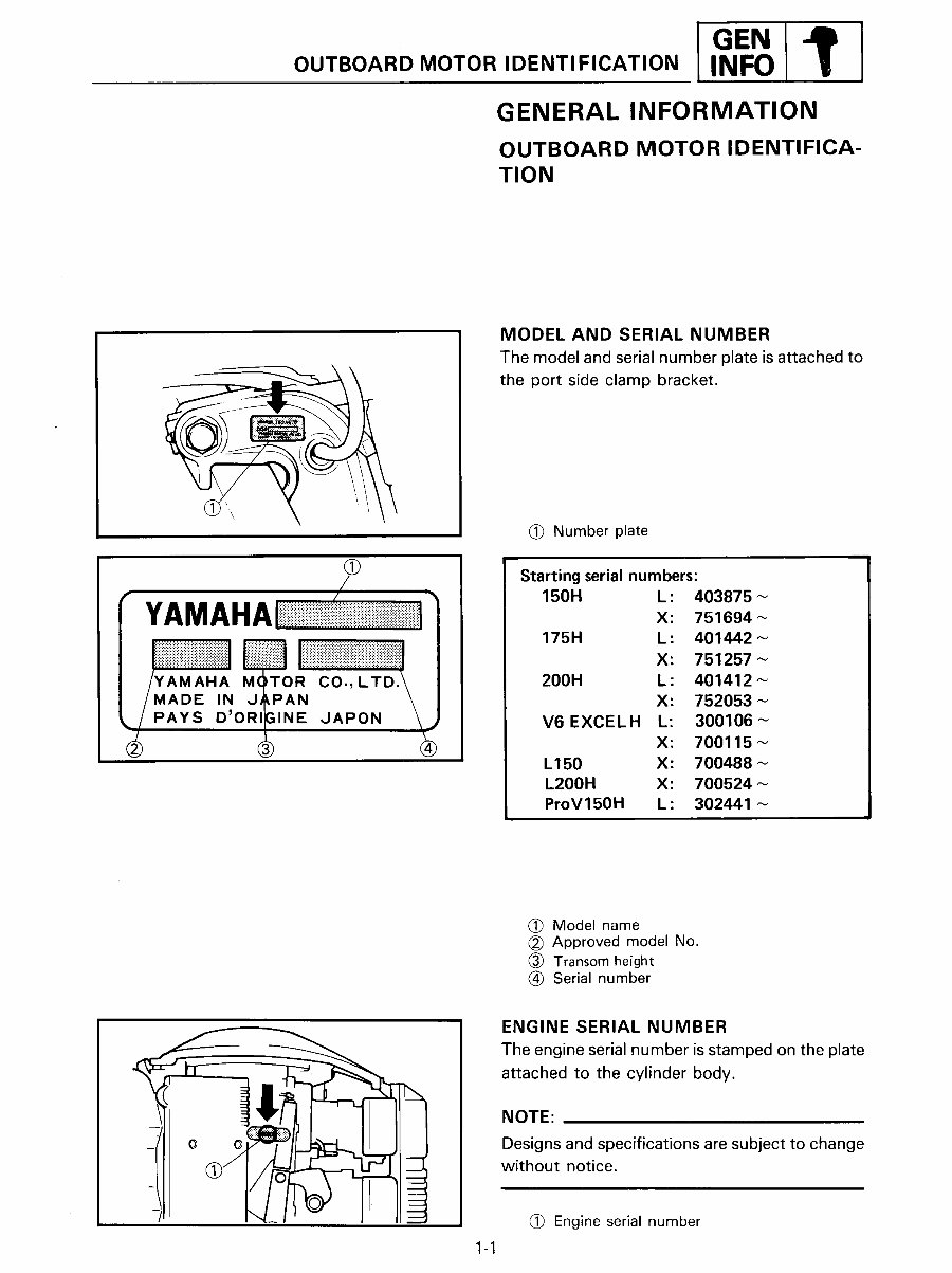
MODEL AND SERIAL NUMBER
The model and serial number plate is attached to
the port side clamp bracket.
@ Number plate
@ Starting serial numbers:
/
i Ii_iiiii!ii_i_ii!iiiiii_!iiii!ili!i!iiil _ lii_ii(i_il i_iii_Aiiii!il / 150H L: 403875_
YAMAHAliiiiiiiiiiiiii!iiiiiiiiiiiiiiiiii!iiiiiiiil ] ×: 51694-
175H L: 401442
X: 751257 ~
/YAMAHA M()TOR CO.,LTD.\ / 200H L: 401412_
/MADE IN J,_PAN \ I X: 752053_
/PAYS D'ORI31NE JAPON \.,) V6EXCELH L: 300106
/ _ X: 700115
_ L150 X: 700488 _
L200H X: 700524
ProV150H L: 302441
(_) Model name
(_ Approved model No.
(_) Transom height
@ Serial number
ENGINE SERIAL NUMBER
The engine serial number is stamped on the plate
_T attached to the cylinder body.
NOTE:
Designs and specifications are subject to change
without notice.
I-_ _ Engine serial number
1-1
°E.
1
INFO j IMPORTANT INFORMATION
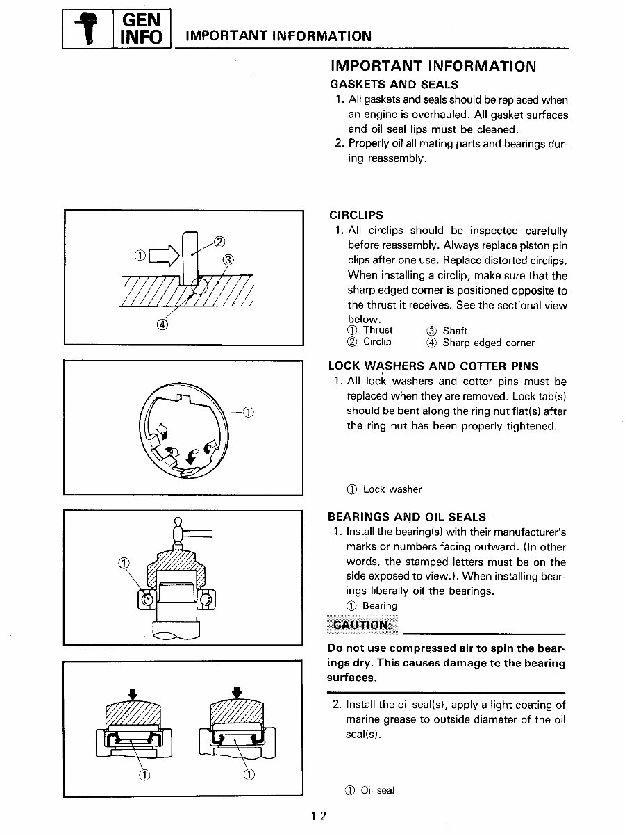
IMPORTANT INFORMATION
GASKETS AND SEALS
1. All gasketsand sealsshouldbe replacedwhen
an engine is overhauled. All gasket surfaces
and oil seal lips must be cleaned.
2. Properlyoil all mating parts and bearingsdur-
ing reassembly.
CIRCLIPS
1. All circlips should be inspected carefully
(_/(_ before reassembly. Always replace piston pin
clips after one use. Replace distorted circlips.
When installing a circllp, make sure that the
/////_/_/_'////_/ sharp edged corner is positioned opposite to
the thrust it receives. See the sectional view
f below.
(_) (_ Thrust (_ Shaft
(_ Circlip @ Sharp edged corner
LOCK WASHERS AND COTTER PINS
1. All lock washers and cotter pins must be
replaced when they are removed. Lock tab(s)
should be bent along the ring nut flat(s) after
the ring nut has been properly tightened.
(_ Lock washer
BEARINGS AND OIL SEALS
1. Install the bearing(s) with their manufacturer's
marks or numbers facing outward. (In other
words, the stamped letters must be on the
side exposed to view.). When installing bear-
ings liberally oil the bearings.
(_ Bearing
Do not use compressed air to spin the bear-
ings dry. This causes damage ta the bearing
surfaces.
,nsta,, sea,,s i c
marine grease to outside diameter of the oil
seal(s).
(_ Oil seal
1-2
GEN --=,==
TECHNICAL FEATURES INFO |
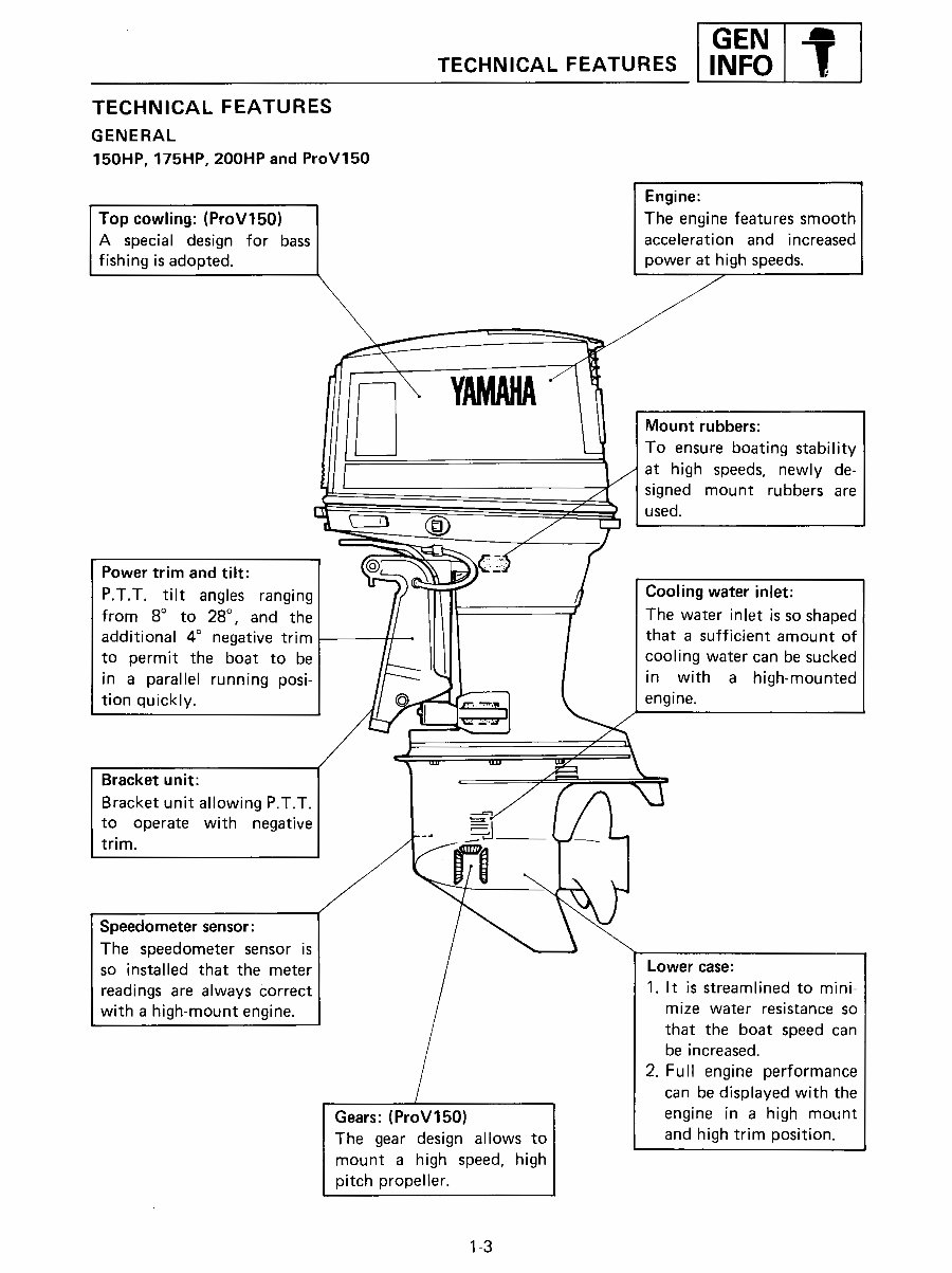
TECHNICAL FEATURES
GENERAL
150HP, 175HP, 200HP and ProV150
Engine:
Top cowling: (ProV150) The engine features smooth
A special design for bass acceleration and increased
fishing is adopted, power at high speeds,
Mount rubbers:
To ensure boating stability
at high speeds, newly de-
signed mount rubbers are
(_) used.
Power trim and tilt:
P.T.T. tilt angles ranging Cooling waterinlet:
from 8° to 28° , and the The water inlet is so shaped
additional 4° negative trim that a sufficient amount of
to permit the boat to be cooling water can be sucked
in a parallel running posi- in with a high-mounted
tion quickly, engine.
Bracket unit:
Bracket unit allowing P.T.T.
to operate with negative ._l
trim.
Speedometer sensor:
The speedometer sensor is
so installed that the meter Lower case:
readings are always Correct 1. It is streamlined to mini-
with a high-mount engine, mize water resistance so
that the boat speed can
be increased.
2. Full engine performance
can be displayed with the
Gears: (ProV150) engine in a high mount
The gear design allows to and high trim position.
mount a high speed, high
pitch propeller.
1-3
You're Reading a Preview
What's Included?
Fast Download Speeds
Online & Offline Access
Access PDF Contents & Bookmarks
Full Search Facility
Print one or all pages of your manual
$31.99
Viewed 32 Times Today


Secure transaction
What's Included?
Fast Download Speeds
Online & Offline Access
Access PDF Contents & Bookmarks
Full Search Facility
Print one or all pages of your manual
$31.99
- Get the most out of your Yamaha 150/175/200HP 2-Stroke Outboard with the 1987-1989 Yamaha Service & Repair Manual.
- Perfect for both professional marine mechanics and boating enthusiasts, this manual provides detailed maintenance, troubleshooting, and repair information.
- Includes comprehensive step-by-step instructions, vivid illustrations, and elaborate exploded-view diagrams.
- Yamaha’s 150/175/200HP 2-Stroke Outboards are known for their power and durability, requiring expert care and attention for peak performance.
- Equips you with the manufacturer’s own procedures for all maintenance and repair aspects.
- Covers engine maintenance, fuel system overhauls, and electrical diagnostics with practical information.
- Digital format allows for easy access on various devices, including PCs, tablets, and smartphones, streamlining the search for information.
- Printable: Yes
- Language: English
- Compatibility: Compatible across a wide range of devices including PCs, Macs, smartphones, and tablets.
- Requirements: A PDF reader like Adobe Reader (free)


