E HOW TO USE THIS MANUAL MANUAL FORMAT All of the procedures in this manual are organized in a sequential, step-by-step format. The information has been compiled to provide the mechanic with an easy to read, handy refer- ence that contains comprehensive explanations of all disassembly, repair, assembly, and inspection operations. For instance, the condition of a faulty component will precede an arrow symbol and the course of action required will follow the symbol. • Bearings Pitting/scratches → Replace. To assist you in finding your way through this manual, the section title and major heading is given at the top of every page. MODEL INDICATION Multiple models are mentioned in this manual and their model indications are noted as fol- lows. ILLUSTRATIONS The illustrations within this service manual represent all of the designated models. CROSS REFERENCES The cross references have been kept to a minimum. Cross references will direct you to the appropriate section or chapter. Model name F115AET FL115AET USA and Canada name F115TR LF115TR Indication F115AET FL115AET
E IMPORTANT INFORMATION In this Service Manual particularly important information is distinguished in the following ways. The Safety Alert Symbol means ATTENTION! BECOME ALERT! YOUR SAFETY IS INVOLVED! WARNING Failure to follow WARNING instructions could result in severe injury or death to the machine operator, a bystander, or a person inspecting or repairing the outboard motor. CAUTION: A CAUTION indicates special precautions that must be taken to avoid damage to the out- board motor. NOTE: A NOTE provides key information to make procedures easier or clearer.
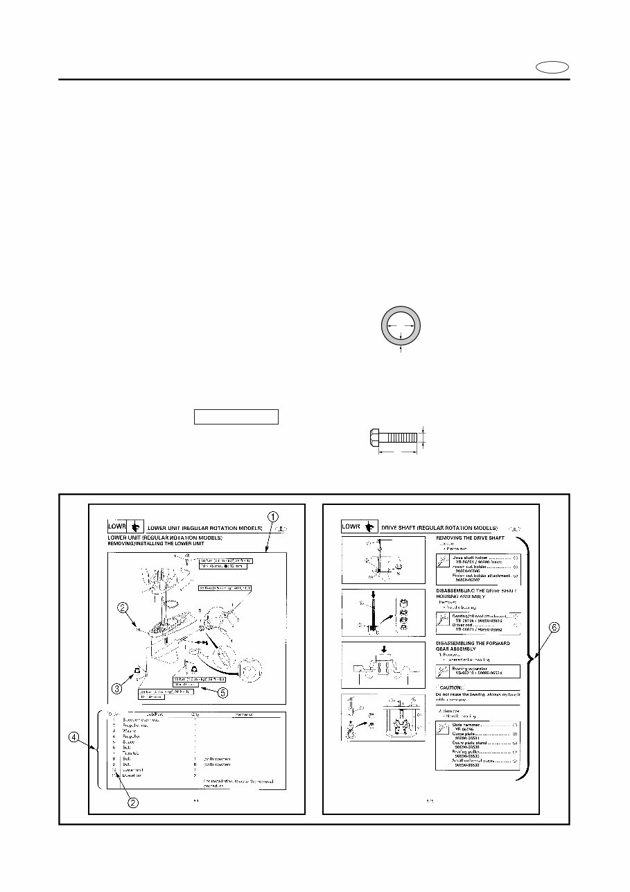
E HOW TO USE THIS MANUAL 1 The main points regarding removing/installing and disassembling/assembling procedures are shown in the exploded views. 2 The numbers in the exploded views indicate the required sequence of the procedure and should be observed accordingly. 3 Symbols are used in the exploded views to indicate important aspects of the procedure. A list of meanings for these symbols is provided on the following page. 4 It is important to refer to the job instruction charts at the same time as the exploded views. These charts list the sequence that the procedures should be carried out in, as well as pro- viding explanations on part names, quantities, dimensions and important points relating to each relevant task. Example: O-ring size 39.5 × 2.5 mm: inside diameter (D) × ring diameter (d) 5 In addition to tightening torques, the dimensions of the bolts and screws are also men- tioned. Example: Bolt and screw size : bolt and screw diameter (D) × length (L) 6 In addition to the exploded views and job instruction charts, this manual provides individ- ual illustrations when further explanations are required to explain the relevant procedure. d D 10 × 25 mm D L
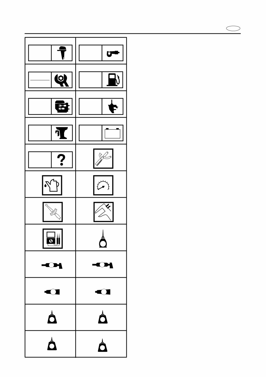
E SYMBOLS Symbols 1 to 9 are designed as thumb- tabs to indicate the content of a chapter. 1 General information 2 Specifications 3 Periodic inspections and adjustments 4 Fuel system 5 Power unit 6 Lower unit 7 Bracket unit 8 Electrical systems 9 Trouble analysis Symbols 0 to E indicate specific data. 0 Special tool A Specified liquid B Specified engine speed C Specified torque D Specified measurement E Specified electrical value [Resistance (Ω), Voltage (V), Electric current (A)] Symbol F to H in an exploded diagram indicate the grade of lubricant and the loca- tion of the lubrication point. F Apply Yamaha 4-stroke outboard motor oil (TC-W3) G Apply water resistant grease (Yamaha grease A, Yamaha marine grease) H Apply molybdenum disulfide oil Symbols I to N in an exploded diagram indicate the grade of the sealing or locking agent and the location of the application point. I Apply Gasket Maker ® J Apply Yamabond #4 (Yamaha bond number 4) K Apply LOCTITE ® No. 271 (Red LOCTITE) L Apply LOCTITE ® No. 242 (Blue LOCTITE) M Apply LOCTITE ® No. 572 N Apply silicon sealant 1 2 3 4 5 6 7 8 9 0 A B C D E F G H I J K L M N GEN INFO SPEC INSP ADJ FUEL POWR LOWR BRKT – + ELEC TRBL ANLS T R . . E A M GM 4 271 LT 242 LT 572 LT SS
E CONTENTS GENERAL INFORMATION SPECIFICATIONS PERIODIC INSPECTIONS AND ADJUSTMENTS FUEL SYSTEM POWER UNIT LOWER UNIT BRACKET UNIT ELECTRICAL SYSTEMS TROUBLE ANALYSIS
F D ES TABLE DES MATIERES INFORMATIONS GENERALES SPECIFICATIONS INSPECTION PERIODIQUE ET REGLAGE SYSTEME D’ALIMENTATION MOTEUR BLOC DE PROPULSION UNITE DE SUPPORT EQUIPEMENT ELECTRIQUE DEPANNAGE INHALT ALLGEMEINES TECHNISCHE DATEN REGELMÄßIGE INSPEKTIONEN UND EINSTELLUNGEN KRAFTSTOFFAN- LAGE MOTOR ANTRIEBSEINHEIT MOTORHALTERUNG ELEKTRISCHE ANLAGE STÖRUNGSSUCHE TABLA DE MATERIAS INFORMACIÓN GENERAL 1 ESPECIFICACIONES 2 SPEC INSPECCIÓN PERIÓDICA Y AJUSTE 3 SISTEMA DE COMBUSTIBLE 4 FUEL MOTOR 5 POWR UNIDAD INFERIOR 6 LOWR UNIDAD DE MÉNSULA 7 BRKT SISTEMAS ELÉCTRICOS 8 ELEC ANÁLISIS DE AVERÍAS 9 GEN INFO INSP ADJ – + TRBL ANLS
E 2 3 4 5 6 7 8 9 GEN INFO CHAPTER 1 GENERAL INFORMATION IDENTIFICATION ............................................................................................ 1-1 SERIAL NUMBER ..................................................................................... 1-1 STARTING SERIAL NUMBERS ............................................................... 1-1 SAFETY WHILE WORKING ............................................................................ 1-2 FIRE PREVENTION ................................................................................... 1-2 VENTILATION........................................................................................... 1-2 SELF-PROTECTION.................................................................................. 1-2 OILS, GREASES AND SEALING FLUIDS................................................ 1-2 GOOD WORKING PRACTICES ................................................................ 1-3 DISASSEMBLY AND ASSEMBLY ........................................................... 1-4 SPECIAL TOOLS ............................................................................................. 1-5 MEASURING ............................................................................................ 1-5 REMOVING AND INSTALLING ............................................................... 1-7
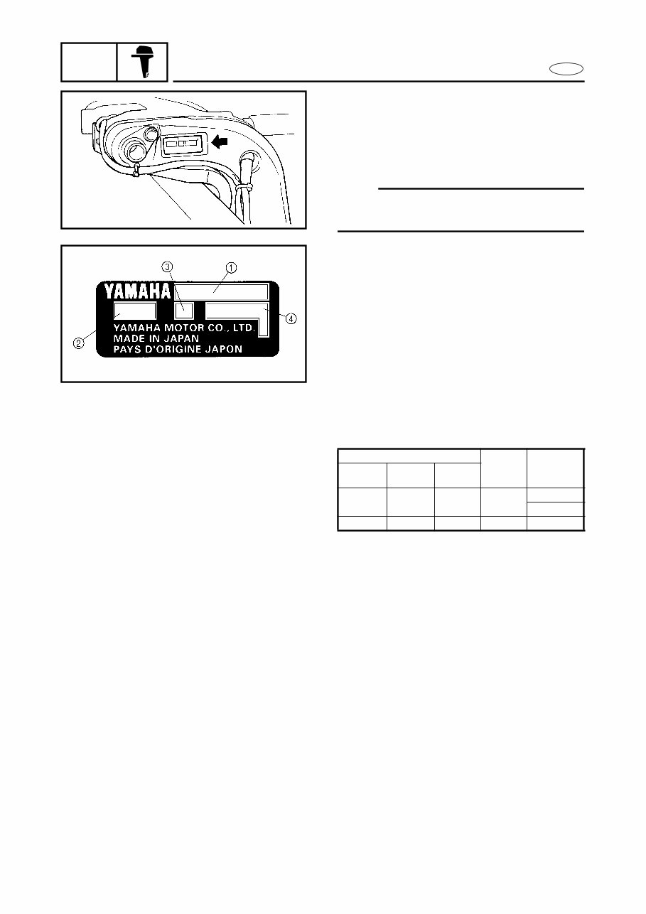
1-1 GEN INFO E IDENTIFICATION IDENTIFICATION 1 SERIAL NUMBER The outboard motor’s serial number is stamped on a label which is attached to the port side of the clamp bracket. NOTE: If the serial number label is removed, “VOID” marks will be appear on the label. 1 Model name 2 Approved model code 3 Transom height 4 Serial number S68V1010 1020 STARTING SERIAL NUMBERS The starting serial number blocks are as fol- lows: Model name Approved model code Starting serial number World- wide USA Canada F115AET F115TR F115TR 68V L: 300101 - X: 700101 - FL115AET LF115TR LF115TR 68W X: 800101 -
This service repair manual for the Yamaha F115A, FL115A Outboard provides comprehensive descriptions of disassembly, repair, assembly, adjustment, and inspection procedures in a sequential, step-by-step format. Each page includes the section title and major heading to help you navigate the manual, and an index to contents is provided at the beginning of each section.
This manual consists of 713 pages and is of high quality, with all pages being printable. It is available in English, French, German, and Spanish languages. The file format is PDF, compatible with all versions of Windows, Mac, and Linux. Adobe Reader and Win are the only requirements for accessing this manual, eliminating the need for shipping or waiting for a CD-ROM.
Recently Viewed
5,521,897Happy Clients
2,594,462eManuals
1,120,453Trusted Sellers
15Years in Business
Price:
Actual Price:
Yamaha F115A,FL115A Outboard Service Repair Manual