

2000-2003 Yamaha 115hp Outboard Service Manual
What's Included?
Fast Download Speeds
Online & Offline Access
Access PDF Contents & Bookmarks
Full Search Facility
Print one or all pages of your manual

F115C
LF115C
SERVICE MANUAL
68V-28197-1F-11 LIT-18616-02-71
*LIT186160271*

E
NOTICE
This manual has been prepared by Yamaha primarily for use by Yamaha dealers and their
trained mechanics when performing maintenance procedures and repairs to Yamaha equip-
ment. It has been written to suit the needs of persons who have a basic understanding of the
mechanical and electrical concepts and procedures inherent in the work, for without such
knowledge attempted repairs or service to the equipment could render it unsafe or unfit for
use.
Because Yamaha has a policy of continuously improving its products, models may differ in
detail from the descriptions and illustrations given in this publication. Use only the latest edi-
tion of this manual. Authorized Yamaha dealers are notified periodically of modifications and
significant changes in specifications and procedures, and these are incorporated in succes-
sive editions of this manual.
F115C, LF115C
SERVICE MANUAL
©2003 by Yamaha Motor Corporation, USA
1st Edition, October 2003
All rights reserved.
Any reprinting or unauthorized use
without the written permission of
Yamaha Motor Corporation, USA
is expressly prohibited.
Printed in USA
LIT-18616-02-71
E
HOW TO USE THIS MANUAL
MANUAL FORMAT
All of the procedures in this manual are organized in a sequential, step-by-step format. The
information has been compiled to provide the mechanic with an easy to read, handy refer-
ence that contains comprehensive explanations of all disassembly, repair, assembly, and
inspection operations.
For instance, the condition of a faulty component will precede an arrow symbol and the
course of action required will follow the symbol.
• Bearings
Pitting/scratches → Replace.
To assist you in finding your way through this manual, the section title and major heading is
given at the top of every page.
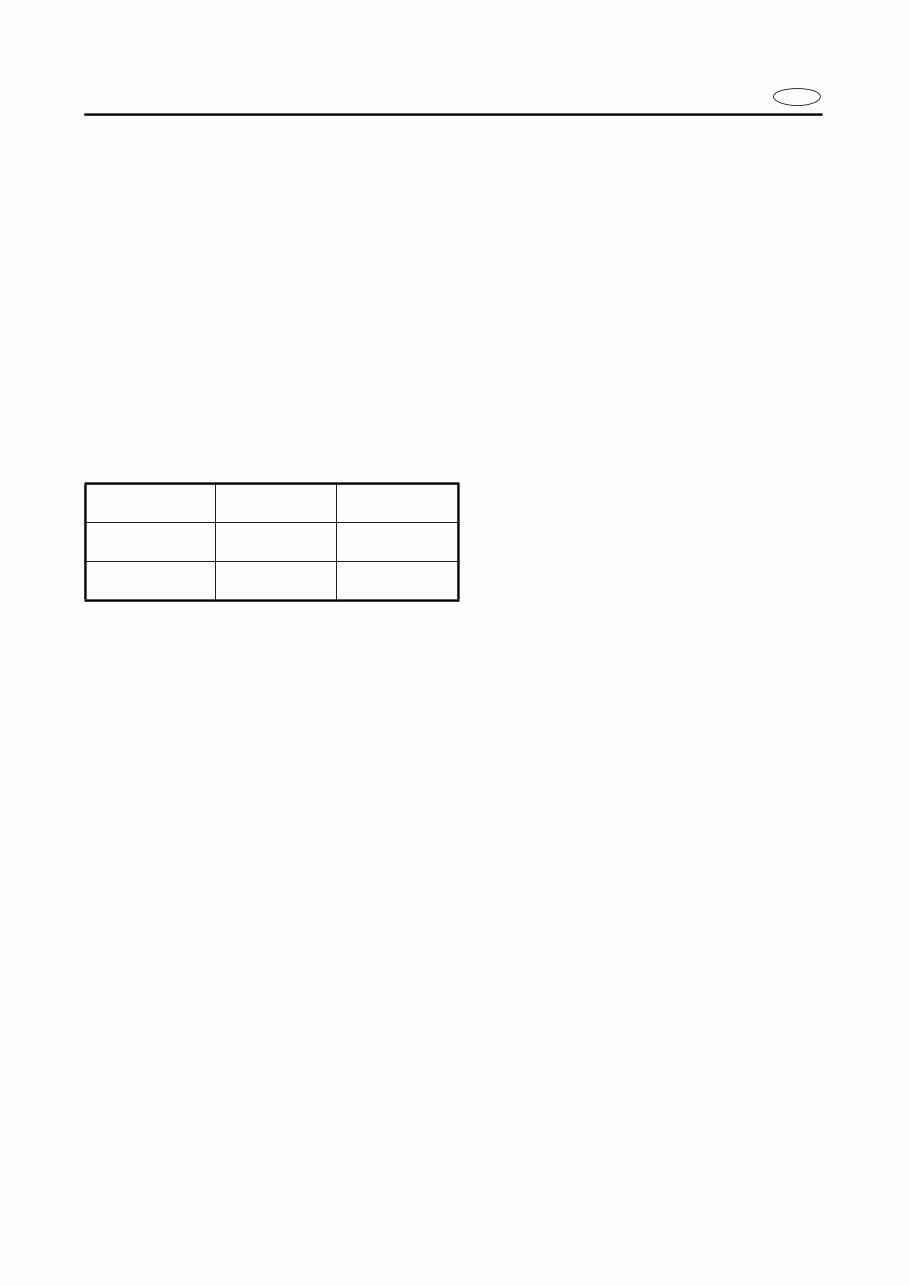
MODEL INDICATION
Multiple models are mentioned in this manual and their model indications are noted as fol-
lows.
ILLUSTRATIONS
The illustrations within this service manual represent all of the designated models.
CROSS REFERENCES
The cross references have been kept to a minimum. Cross references will direct you to the
appropriate section or chapter.
Model name F115AET FL115AET
USA and
Canada name
F115TR LF115TR
Indication F115AET FL115AET
E
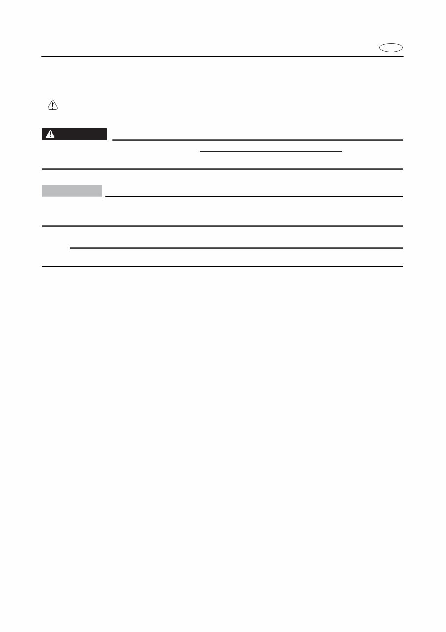
IMPORTANT INFORMATION
In this Service Manual particularly important information is distinguished in the following
ways.
The Safety Alert Symbol means ATTENTION! BECOME ALERT! YOUR SAFETY IS
INVOLVED!
WARNING
Failure to follow WARNING instructions could result in severe injury or death to the machine
operator, a bystander, or a person inspecting or repairing the outboard motor.
CAUTION:
A CAUTION indicates special precautions that must be taken to avoid damage to the out-
board motor.
NOTE:
A NOTE provides key information to make procedures easier or clearer.
E
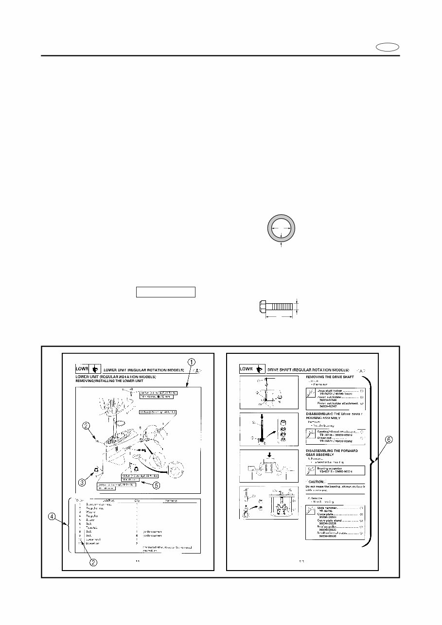
HOW TO USE THIS MANUAL
1 The main points regarding removing/installing and disassembling/assembling procedures
are shown in the exploded views.
2 The numbers in the exploded views indicate the required sequence of the procedure and
should be observed accordingly.
3 Symbols are used in the exploded views to indicate important aspects of the procedure.
A list of meanings for these symbols is provided on the following page.
4 It is important to refer to the job instruction charts at the same time as the exploded views.
These charts list the sequence that the procedures should be carried out in, as well as pro-
viding explanations on part names, quantities, dimensions and important points relating
to each relevant task.
Example:
O-ring size 39.5 × 2.5 mm: inside diameter (D) × ring diameter (d)
5 In addition to tightening torques, the dimensions of the bolts and screws are also men-
tioned.
Example:
Bolt and screw size : bolt and screw diameter (D) × length (L)
6 In addition to the exploded views and job instruction charts, this manual provides individ-
ual illustrations when further explanations are required to explain the relevant procedure.
d
D
10 × 25 mm
D
L
E
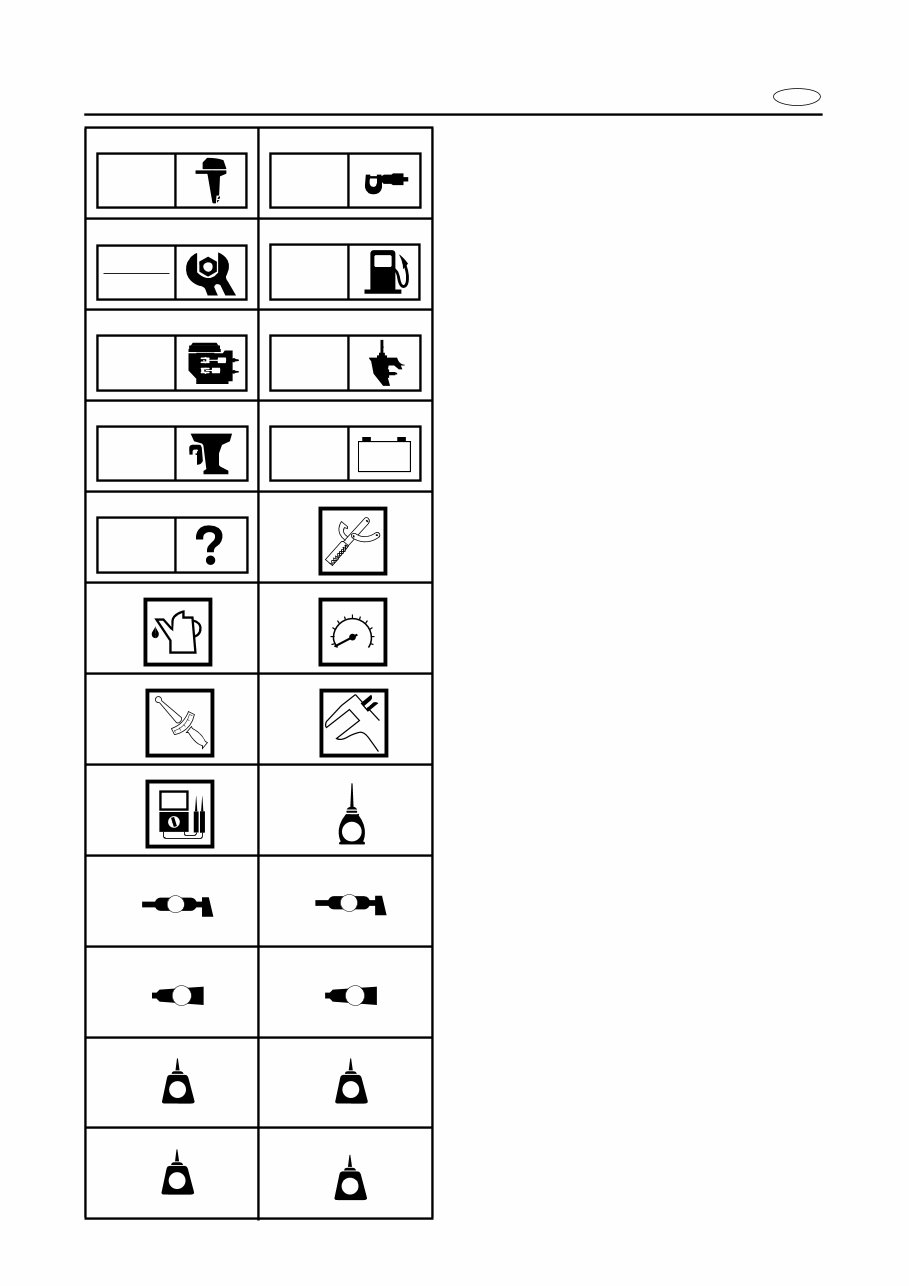
SYMBOLS
Symbols 1 to 9 are designed as thumb-
tabs to indicate the content of a chapter.
1 General information
2 Specifications
3 Periodic inspections and adjustments
4 Fuel system
5 Power unit
6 Lower unit
7 Bracket unit
8 Electrical systems
9 Trouble analysis
Symbols 0 to E indicate specific data.
0 Special tool
A Specified liquid
B Specified engine speed
C Specified torque
D Specified measurement
E Specified electrical value
[Resistance (Ω), Voltage (V), Electric current
(A)]
Symbol F to H in an exploded diagram
indicate the grade of lubricant and the loca-
tion of the lubrication point.
F Apply Yamaha 4-stroke outboard motor oil
(TC-W3)
G Apply water resistant grease
(Yamaha grease A, Yamaha marine grease)
H Apply molybdenum disulfide oil
Symbols I to N in an exploded diagram
indicate the grade of the sealing or locking
agent and the location of the application
point.
I Apply Gasket Maker
®
J Apply Yamabond #4
(Yamaha bond number 4)
K Apply LOCTITE
®
No. 271 (Red LOCTITE)
L Apply LOCTITE
®
No. 242 (Blue LOCTITE)
M Apply LOCTITE
®
No. 572
N Apply silicon sealant
1 2
3 4
5 6
7 8
9 0
A B
C D
E F
G H
I J
K L
M N
GEN
INFO
SPEC
INSP
ADJ
FUEL
POWR LOWR
BRKT
– +
ELEC
TRBL
ANLS
T
R
.
.
E
A M
GM
4
271
LT
242
LT
572
LT SS
E
CONTENTS
GENERAL INFORMATION
1
SPECIFICATIONS
2
SPEC
PERIODIC INSPECTIONS AND
ADJUSTMENTS
3
FUEL SYSTEM
4
FUEL
POWER UNIT
5
POWR
LOWER UNIT
6
LOWR
BRACKET UNIT
7
BRKT
ELECTRICAL SYSTEMS
8
ELEC
TROUBLE ANALYSIS
9
GEN
INFO
INSP
ADJ
– +
TRBL
ANLS
E
1
2
3
4
5
6
7
8
9
GEN
INFO
CHAPTER 1
GENERAL INFORMATION
IDENTIFICATION ............................................................................................ 1-1
SERIAL NUMBER ..................................................................................... 1-1
STARTING SERIAL NUMBERS ............................................................... 1-1
SAFETY WHILE WORKING ............................................................................ 1-2
FIRE PREVENTION ................................................................................... 1-2
VENTILATION........................................................................................... 1-2
SELF-PROTECTION.................................................................................. 1-2
OILS, GREASES AND SEALING FLUIDS................................................ 1-2
GOOD WORKING PRACTICES ................................................................ 1-3
DISASSEMBLY AND ASSEMBLY ........................................................... 1-4
SPECIAL TOOLS ............................................................................................. 1-5
MEASURING ............................................................................................ 1-5
REMOVING AND INSTALLING ............................................................... 1-7
1-1
GEN
INFO
E
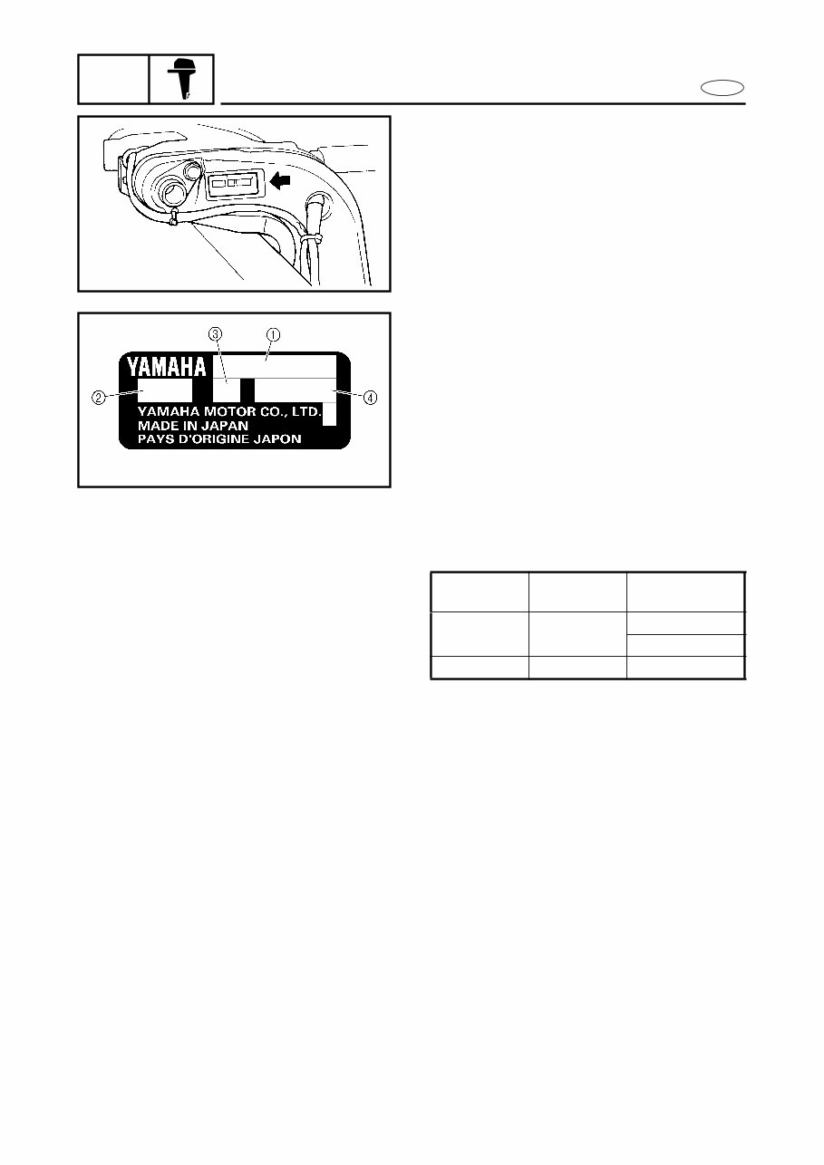
IDENTIFICATION
IDENTIFICATION 1
SERIAL NUMBER
The outboard motor serial number is
stamped on a label attached to the port
clamp bracket.
S68V1010
1 Model name
2 Approved model code
3 Transom height
4 Serial number
1020
STARTING SERIAL NUMBERS
The starting serial number blocks are as fol-
lows:
Model name
Approved
model code
Starting
serial number
F115TR 68V
L: 1016859 -
X: 1016859 -
LF115TR 68W X: 1000743 -
1-2
GEN
INFO
E
SAFETY WHILE WORKING
SAFETY WHILE WORKING 1
The procedures given in this manual are
those recommended by Yamaha to be fol-
lowed by Yamaha dealers and their
mechanics.
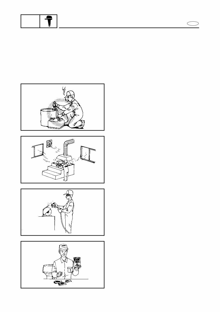
FIRE PREVENTION
Gasoline (petrol) is highly flammable.
Petroleum vapor is explosive if ignited.
Do not smoke while handling gasoline and
keep it away from heat, sparks and open
flames.
1030
VENTILATION
Petroleum vapor is heavier than air and is
deadly if inhaled in large quantities. Engine
exhaust gases are harmful to breathe.
When test-running an engine indoors,
maintain good ventilation.
1040
SELF-PROTECTION
Protect your eyes with suitable safety
glasses or safety goggles, when grinding or
when doing any operation which may
cause particles to fly off. Protect hands and
feet by wearing safety gloves or protective
shoes if appropriate to the work you are
doing.
1050
OILS, GREASES AND SEALING
FLUIDS
Use only genuine Yamaha oils, greases and
sealing fluids or those recommended by
Yamaha.
1060
You're Reading a Preview
What's Included?
Fast Download Speeds
Online & Offline Access
Access PDF Contents & Bookmarks
Full Search Facility
Print one or all pages of your manual
$32.99
Viewed 50 Times Today


Secure transaction
What's Included?
Fast Download Speeds
Online & Offline Access
Access PDF Contents & Bookmarks
Full Search Facility
Print one or all pages of your manual
$32.99
This manual covers the 2000-2003 Yamaha 115 Outboard, including all 115hp model outboards from 2000-2003.
It is the same manual that professional mechanics use for fixing your outboard, now available for DIY enthusiasts. It contains detailed removal and assembly instructions for any repair your motor may require, along with illustrations and technical information.
The manual covers all repair topics:
- General Information (Identification, Safety, Tools)
- Specifications (General and Maintenance)
- Periodic Inspection and Adjustment
- Fuel and Lubrication System
- Power Unit
- Lower Unit
- Bracket Unit
- Electrical System
- Troubleshooting
You can easily browse the manual via bookmarks, zoom in/out of specific pages, and print out the necessary pages for the repairs. Make back up copies to keep forever and eliminate worries about destroying your manual with dirt and grease.
Get this manual instantly without waiting for days!


