00 0 1 2 3 4 5 6 7 8 9 10 11 Precautions............................................................... 00-i Precautions ............................................................ 00-1 General Information ................................................... 0-i General Information ............................................... 0A-1 Maintenance and Tune-Up..................................... 0B-1 Power Head................................................................. 1-i Precautions .............................................................. 1-1 Engine Control ....................................................... 1A-1 Engine Electrical Devices....................................... 1C-1 Power Unit Mechanical .......................................... 1D-1 Power Unit Lubrication ........................................... 1E-1 Power Unit Cooling System ................................... 1F-1 Fuel System ...........................................................1G-1 Ignition System....................................................... 1H-1 Starting System....................................................... 1I-1 Charging System.................................................... 1K-1 Mid Unit ....................................................................... 2-i Precautions .............................................................. 2-1 Housing and Bracket .............................................. 2A-1 Power Trim and Tilt ................................................ 2B-1 Lower Unit ................................................................... 3-i Precautions .............................................................. 3-1 Right Hand Rotation Unit ....................................... 3A-1 Wire / Hose Routing ................................................... 4-i Precautions .............................................................. 4-1 Wire Routing .......................................................... 4A-1 Fuel / Water Hose Routing ..................................... 4B-1 TABLE OF CONTENTS
Table of Contents 00- i 00 Section 00 CONTENTS Precautions Precautions ............................................... 00-1 Precautions........................................................... 00-1 General Precautions ........................................... 00-1
00-1 Precautions: Precautions Precautions Precautions General Precautions ZAJ6110000001 WARNING ! • Proper service and repair procedures are important for the safety of the service mechanic and the safety and reliability of the outboard motor. • To avoid eye injury, always wear protective glasses when filing metals, working on a grinder, or doing other work, which could cause debris. • When two or more persons work together, pay attention to the safety of each other. • When it is necessary to run the outboard motor indoors, make sure that exhaust gas is vented outdoors. • When testing an outboard motor in the water, ensure that the necessary safety equipment is on board. Such equipment includes: flotation aids for each person, fire extinguisher, distress signals, anchor, paddles, bilge pump, first aid kit, emergency starter rope, etc. • When working with toxic or flammable materials, make sure that the area you work in is well ventilated and that you follow all of the material manufacturer’s instructions. • Never use gasoline as a cleaning solvent. • To avoid getting burned, do not touch the engine, engine oil or exhaust system during or shortly after engine operation. • Oil can be hazardous. Children and pets may be harmed from contact with oil. Keep new and used oil away from children and pets. To minimize your exposure to oil, wear a long sleeve shirt and moisture-proof gloves (such as latex gloves) when changing oil. If oil contacts your skin, wash thoroughly with soap and water. Launder any clothing or rags if wet with oil. Recycle or properly dispose of used oil. • After servicing the fuel, lubrication, cooling and/or the exhaust system, check all lines and fittings related to the system for leaks. • Carefully adhere to the battery handling instructions laid out by the battery supplier.
Precautions: 00-2 CAUTION • If parts replacement is necessary, replace the parts with Suzuki Genuine Parts or their equivalent. • When removing parts that are to be reused, keep them arranged in an orderly manner so that they may be reinstalled in the proper order and orientation. • Be sure to use special tools where instructed. • Make sure that all parts used in assembly are clean and also lubricated when specified. • When use of a certain type of lubricant, bond, or sealant is specified, be sure to use the specified type. • When removing the battery, disconnect the negative cable first and then the positive cable. When reconnecting the battery, connect the positive cable first and then the negative cable. • When performing service to electrical parts, if the service procedures do not require using battery power, disconnect the negative cable at the battery. • Tighten cylinder head and case bolts and nuts, beginning with larger diameter and ending with smaller diameter. Always tighten from inside to outside diagonally to the specified tightening torque. • Whenever you remove oil seals, gaskets, packing, O-rings, locking washers, locking nuts, cotter pins, circlips, and certain other parts as specified, always replace them with new. Also, before installing these new parts, be sure to remove any left over material from the mating surfaces. • Never reuse a circlip. When installing a new circlip, take care not to expand the end gap larger than required to slip the circlip over the shaft. After installing a circlip, always ensure that it is completely seated in its groove and securely fitted. • Use a torque wrench to tighten fasteners to the torque values when specified. • Remove grease or oil from screw / bolt threads unless a lubricant is specified. • After assembly, check parts for tightness and operation. • To protect the environment, do not unlawfully dispose of used motor oil, other fluids or batteries. • To protect the Earth's natural resources, properly dispose of used motor parts.
00-3 Precautions:
Table of Contents 0- i 0 Section 0 CONTENTS General Information General Information ................................ 0A-1 General Description ............................................. 0A-1 Symbols .............................................................. 0A-1 Abbreviations ...................................................... 0A-2 Wire Color Symbols ............................................ 0A-2 Warning, Caution and Information Label Locations........................................................... 0A-3 Genuine Parts Description .................................. 0A-3 Outboard Motor Identification Number Location ............................................................ 0A-3 Fuel and Oil Recommendations .......................... 0A-4 Break-In Procedures ........................................... 0A-4 Propeller Selection Guide ................................... 0A-5 Battery Requirement ........................................... 0A-5 Specifications ....................................................... 0A-6 Specifications ...................................................... 0A-6 Service Data ....................................................... 0A-8 Tightening Torque Specifications ...................... 0A-13 Special Tools and Equipment ........................... 0A-14 Recommended Service Material ....................... 0A-14 Special Tool ...................................................... 0A-15 Maintenance and Tune-Up ...................... 0B-1 Precautions........................................................... 0B-1 Precautions for Maintenance .............................. 0B-1 General Description ............................................. 0B-1 Recommended Oil and Lubricants ...................... 0B-1 Scheduled Maintenance ...................................... 0B-1 Periodic Maintenance Schedule Chart ................ 0B-1 Lubrication Point ................................................. 0B-2 Service Instructions ............................................. 0B-3 Engine Oil Level Check ....................................... 0B-3 Engine Oil Change and Engine Oil Filter Replacement ..................................................... 0B-3 Gear Oil Change ................................................. 0B-6 Spark Plug Removal and Installation .................. 0B-6 Spark Plug Inspection and Cleaning ................... 0B-7 Tappet Clearance Inspection and Adjustment .... 0B-8 Idle Speed and Idle Air Control (IAC) Duty Inspection ........................................................ 0B-13 Ignition Timing Inspection ................................. 0B-13 Breather Line and Fuel Line Inspection ............ 0B-14 Low Pressure Fuel Filter Inspection .................. 0B-15 Water Pump and Water Pump Impeller Inspection ........................................................ 0B-16 Propeller / Propeller Nut and Cotter Pin Inspection ........................................................ 0B-16 Anodes Inspection............................................. 0B-17 Bonding Wires Inspection ................................. 0B-18 Battery Inspection ............................................. 0B-18 Bolts and Nuts Inspection ................................. 0B-20 Oil Pressure Check ........................................... 0B-20 Cylinder Compression Pressure Check ............ 0B-21
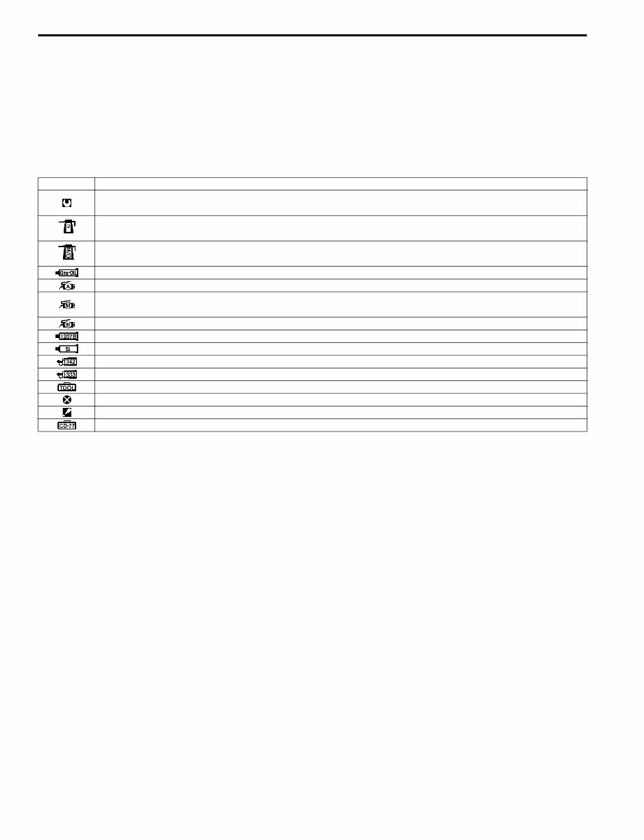
0A-1 General Information: General Information General Information General Description Symbols ZAJ6110101001 Listed in the table below are the symbols indicating instructions and other important information necessary for proper servicing. Please note the definition for each symbol. You will find these symbols used throughout this manual. Refer back to this table if you are not sure of any symbol (s) meanings. Symbol Definition Torque control required. Data beside it indicates specified torque. Apply oil. Use engine oil unless otherwise specified. Apply molybdenum oil solution. (Mixture of engine oil and SUZUKl MOLY PASTE in a ratio of 1 : 1) Apply SUZUKI Outboard Motor Gear Oil. Apply SUZUKI Super Grease A. Apply SUZUKI Moly Paste. 99000-25140 Apply SUZUKI Water Resistant Grease. Apply SUZUKI Bond 1207B. Apply SUZUKI Silicone Seal. Apply SUZUKI Thread Lock 1342. Apply SUZUKI Thread Lock Super 1333B. Use special tool. Do not reuse. Note on reassembly. Use peak voltmeter Stevens CD-77.
General Information: 0A-2 Abbreviations ZAJ6110101002 Abbreviations used in this service manual are as follows: A: ATDC: After Top Dead Center AC: Alternating Current B: BTDC: Before Top Dead Center C: CKP Sensor: Crankshaft Position sensor CMP Sensor: Camshaft Position sensor CTP: Close Throttle Position D: DC: Direct Current DOHC: Double Over Head Camshaft E: ECM: Engine Control Module EX (Ex.): Exhaust F: FP: Fuel Pump G: GND: Ground I: IAC: Idle Air Control IAT: Intake Air Temperature IG: Ignition Ign.: Ignition IN (In.): Intake L: LPS: Lever Position Sensor M: MAP: Manifold Absolute Pressure P: PCV: Positive Crankcase Ventilation PORT: Port PTT: Power Trim and Tilt S: SPS: Shift Position Sensor STBD: Starboard SIGP: Start-In-Gear Protection T: TPS: Throttle Position Sensor Wire Color Symbols ZAJ6110101003 There are two kinds of colored wire used in this product. One is single colored wire and the other is dual colored (striped) wire. The single colored wire uses only one color symbol. example: B (Black). The dual colored wire uses two color symbols. example: Bl/B. The first symbol represents the base color of the wire and the second symbol represents the color of the stripe. Example: Bl/B (Blue with Black stripe). Symbol Wire color Symbol Wire color B Black Lg Light green Bl Blue O Orange Br Brown P Pink Dg Dark green R Red G Green V Violet Gr Gray W White Lbl Light blue Y Yellow B (Base Color) Bl (Blue Color) Bl/B Black (Stripe Color) I9J011010001-02
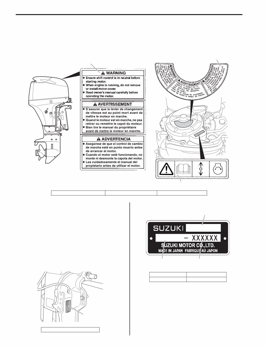
0A-3 General Information: Warning, Caution and Information Label Locations ZAJ6110101004 The figure shows main labels among others that are attached to outboard motor. When servicing outboard motor, refer to WARNING / CAUTION instructions printed on labels. If any WARNING / CAUTION label is found stained or damage, clean or replace it as necessary. Do not reuse a label after it has been removed. Always use new label. Genuine Parts Description ZAJ6110101005 If parts replacement is necessary, Suzuki strongly recommends that you use genuine Suzuki parts or their equivalent. They are precision-made to ensure high quality and correct fit. Outboard Motor Identification Number Location ZAJ6110101006 Model, Pre-fix, Serial number The Model, Pre-fix and Serial number of motor are stamped on a plate attached to the clamp bracket. Example 1 2 3 IAJ611010001-02 1. Label, engine cover 2. Label, mag cover 3. Label S.I.G.P. 1. Identification number plate 1 IAJ611010002-02 1. Model 3. Serial number 2. Pre-fix DF 60A 06002F 3 2 1 IAJ611010003-01
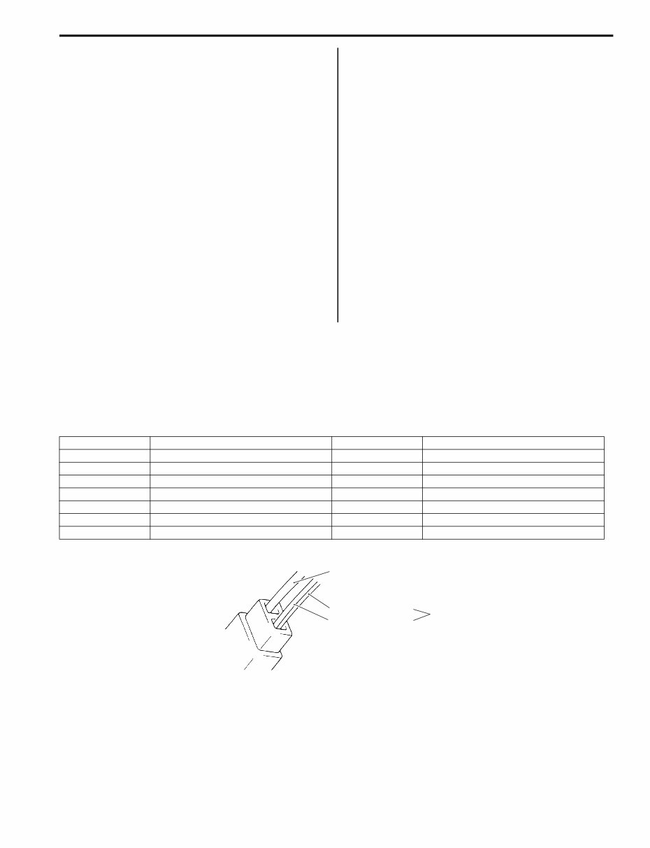
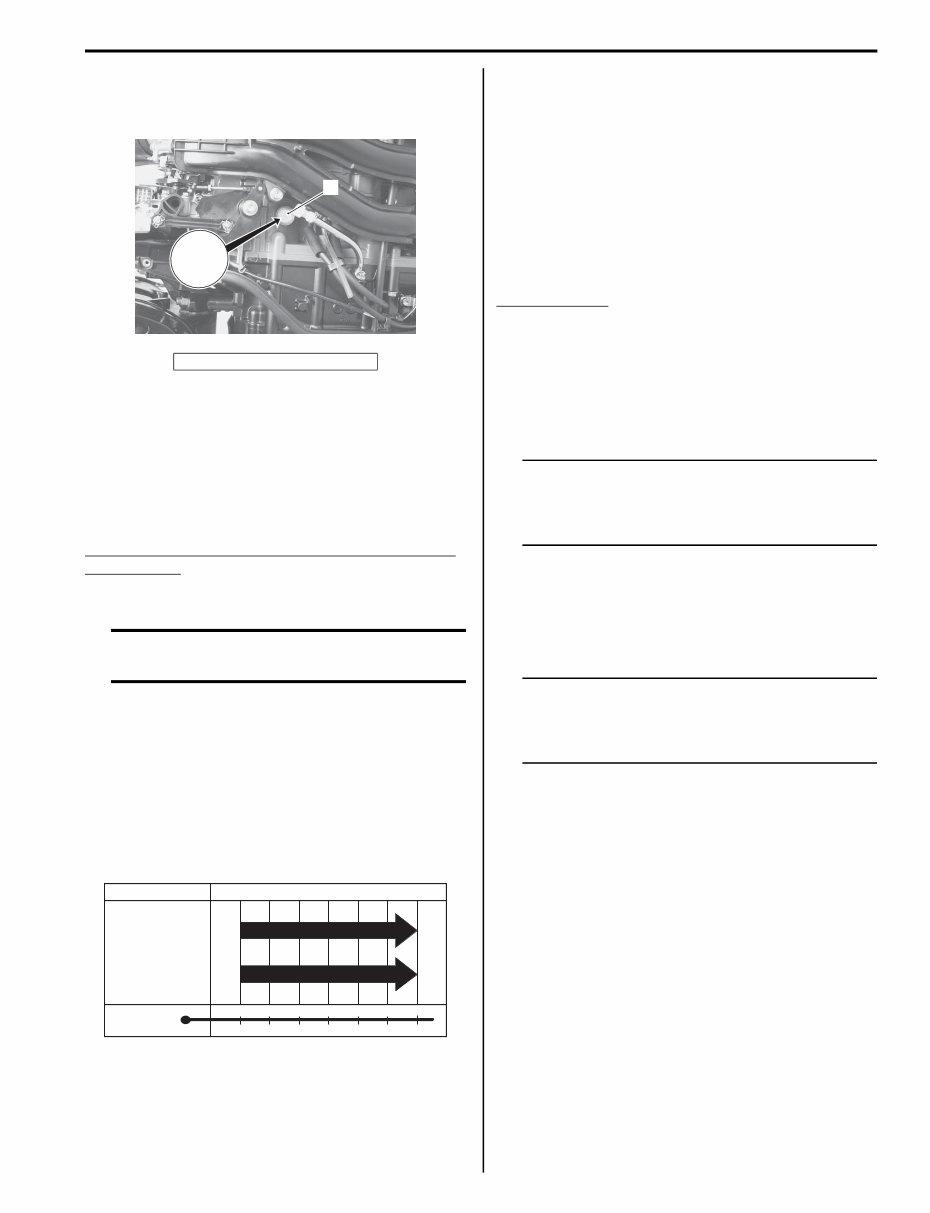
General Information: 0A-4 Engine Serial Number Location A second engine serial number plate is pressed into a boss on the cylinder block. Fuel and Oil Recommendations ZAJ6110101007 Gasoline Suzuki highly recommends that you use alcohol-free unleaded gasoline with a minimum pump octane rating of 87 (R+M/2 method) or 91 (Research method). However, blends of unleaded gasoline and alcohol with equivalent octane content may be used. Allowable maximum blend of a single additive (not combination) 5% Methanol, 10% Ethanol, 15% MTBE CAUTION If leaded gasoline is used, engine damage may result. Use only unleaded gasoline. Engine oil Oil quality is a major contributor to your engine’s performance and life. Always select good quality engine oil. Suzuki recommends the use of a SAE 10 W – 40 NMMA certified oil. If NMMA certified FC-W oil is not available, select a good quality 4-cycle motor oil from the following chart according to the average temperatures in your area. Gear oil Suzuki recommends the use of SUZUKI Outboard Motor Gear Oil. If it is not available, use SAE 90 hypoid gear oil which is rated GL-5 under the API classification system. Break-In Procedures ZAJ6110101008 The first 10 hours are critically important to ensure correct running of either a brand new motor or a motor that has been reconditioned or rebuilt. How the motor is operated during this time will have direct bearing on its life span and long-term durability. Break-in period 10 hours Warm-up recommendation Allow sufficient idling time (more than 5 minutes) for the engine to warm up after cold engine starting. Throttle recommendation NOTE Avoid maintaining a constant engine speed for an extended period at any time during the engine break-in period by varying the throttle position occasionally. First 2 hours For the first 15 minutes, operate the engine in-gear at idling speed. During the remaining 1 hour and 45 minutes, operate the engine in-gear at less than 1/2 (half) throttle (3 000 r/min). NOTE The throttle may be briefly opened beyond the recommended setting to plane the boat, but must be reduced to the recommended setting immediately after planning. Next 1 hour Operate the engine in-gear at less than 3/4 (three - quarter) throttle (4 000 r/min). Last 7 hours Operate the engine in-gear at a desired engine speed. However, do not operate continuously at full throttle for more than 5 minutes. 1. Serial number plate 1 XXXXXX IAJ611010005-01 –20 –10 0 10 20 30 –4 14 32 50 68 86 40 104 TEMP. API Classification SAE Viscosity Grade SG SH SL SJ SM 10W–40 10W–30 F C I9J011010003-02
This service manual is specifically for Suzuki DF40A, DF50A, and DF60A 4-Stroke models.
It provides immediate access to comprehensive repair information, covering all models and repairs for the mentioned vehicles.
This manual is not generic and is tailored to the specific vehicle, the same manual used by dealership technicians for maintenance, service, diagnosis, and repairs.
With this manual, vehicle repair becomes effortless, eliminating the need to search through multiple books. Print only the necessary pages and diagrams, avoiding greasy or torn paper manuals.
It is the best service manual for Suzuki DF40A, DF50A, and DF60A 4-Stroke models, with printable pages for convenient use in your garage or vehicle. Enlarged copies can also be printed.
This highly detailed repair manual includes complete instructions, illustrations, wiring schematics, and diagrams.
Additionally, we offer a 100% satisfaction guarantee. If you are not completely satisfied, you can contact us within 30 days for a refund. Our service and after-sale support are unmatched by any of our competitors.