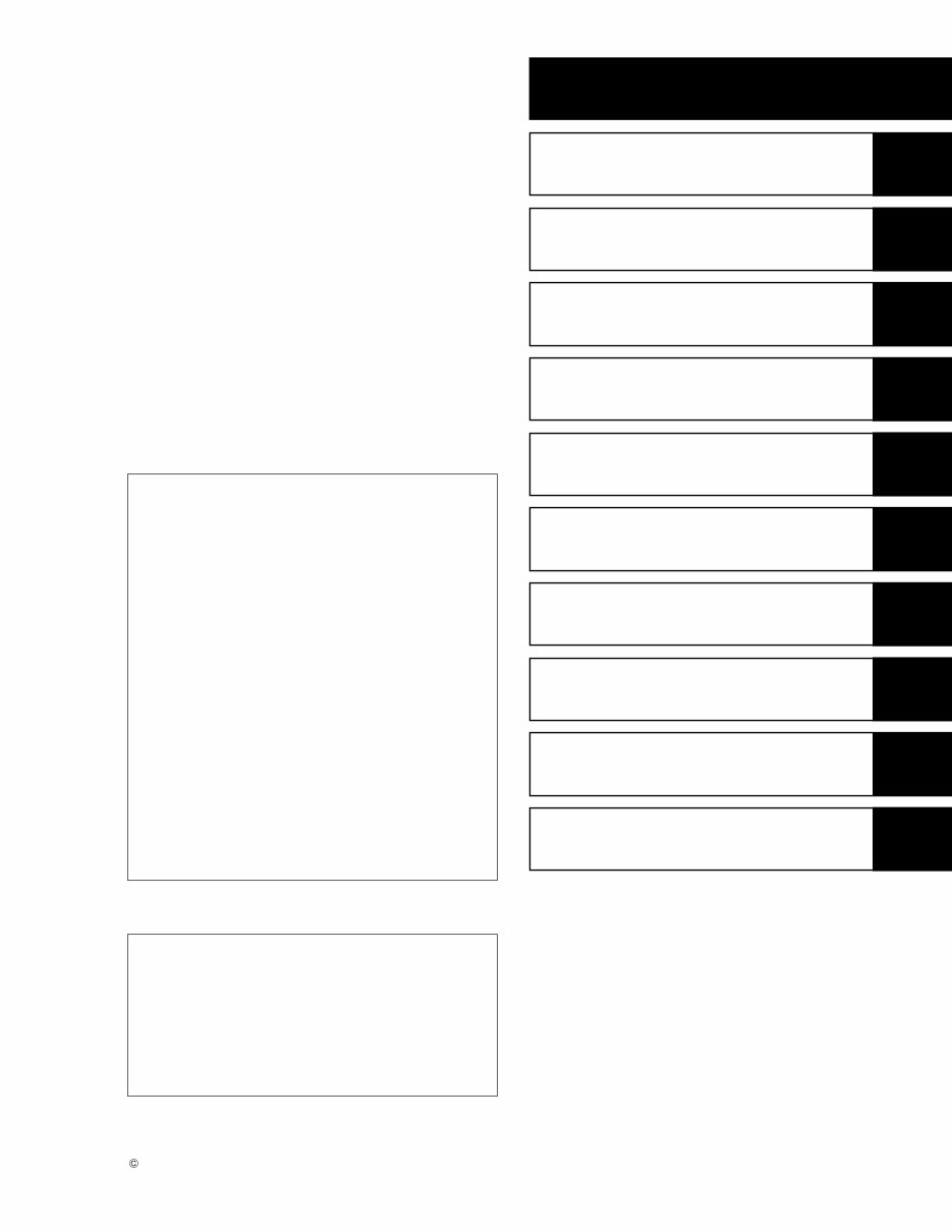
This manual contains an introductory description on SUZUKI Outboard motor DF40/50 and procedures for the inspection, service and overhaul of its main components. General knowledge information is not included. Please read the GENERAL INFORMATION sec- tion to familiarize yourself with basic information concerning this motor. Read and refer to the other sections in this manual for information regard- ing proper inspection and service procedures. This manual will help you better understand this out- board motor so that you may provide your custom- ers with optimum and quick service. GENERAL INFORMATION PERIODIC MAINTENANCE ENGINE CONTROL SYSTEM ELECTRICAL FUEL SYSTEM POWER UNIT MID UNIT POWER TRIM AND TILT LOWER UNIT WIRE / HOSE ROUTING Marine & Power Products Division GROUP INDEX A Apprentice machanics or do-it-yourself me- chanics that don’t have the proper tools and equipment may not be able to properly per- form the services described in this manual. Improper repair may result in injury to the mechanic and may render the engine unsafe for the boat operator and passengers. FOREWORD 1 2 3 4 5 6 7 8 9 10 • This manual has been prepared using the lat- est information available at the time of publi- cation. If a modification has been made since then, differences may exist between the content of this manual and the actual outboard motor. • Illustrations in this manual are used to show the basic principles of operation and work pro- cedures and may not represent the actual outboard motor in exact detail. • This manual is intended for use by technicians who already possess the basic knowledge and skills to service SUZUKI outboard motors. Persons without such knowledge and skills should not attempt to service an outboard engine by relying on this manual only. Instead, please contact your nearby autho- rized SUZUKI outboard motor dealer. COPYRIGHT SUZUKI MOTOR CORPORATION 1998
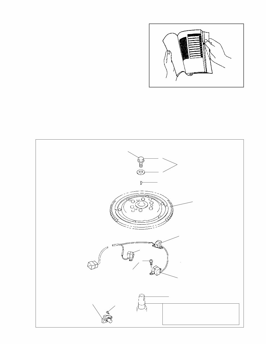
HOW TO USE THIS MANUAL TO LOCATE WHAT YOU ARE LOOKING FOR: 1. The text of this manual is divided into sections. 2. The section titles are listed on the previous page in a GROUP INDEX. Select the section you wish to reference. 3. Holding the manual as shown at the right will al- lowyou to find the first page of the section easily. 4. The first page of each section lists a table of con- tents to easily locate the item and page you need. COMPONENT PARTS AND IMPORTANT ITEM ILLUSTRATIONS Under the name of each system or unit, an exploded view is provided with work instructions and other service information such as the tightening torque, lubrication and locking agent points. Example : 1 Flywheel bolt 2 Washer 3 Key 4 Flywheel 5 CKP sensor 6 Screw 7 CMP sensor 8 Bolt 1 2 3 4 5 5 5 6 7 8 Crankshaft @ 200 N . m (20.0 kg-m, 145 lb.-ft.) o h NOTE: Clean flywheel and crankshaft mating surfaces with cleaning solvent.
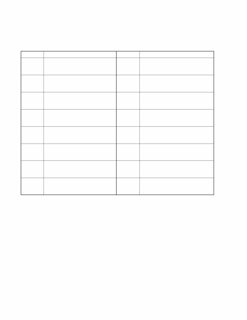
SYMBOL Listed in the table below are the symbols indicating instructions and other important information neces- sary for proper servicing. Please note the definition for each symbol. You will find these symbols used throughout this manual. Refer back to this table if you are not sure of any symbol(s) meanings. Apply THREAD LOCK “1342”. Apply THREAD LOCK SUPER “1333B”. Measure in DC voltage range. Measure in resistance range. Measure in continuity test range. Use peak voltmeter “Stevens CD-77”. Use special tool. Torque control required. Data beside it indicates specified torque. Apply oil. Use engine oil unless otherwise specified. Apply SUZUKI OUTBOARD MOTOR GEAR OIL. Apply SUZUKI SUPER GREASE “A”. Apply SUZUKI WATER RESISTANT GREASE. Apply SUZUKI BOND “1104”. Apply SUZUKI BOND “1207B”. Apply SUZUKI SILICONE SEAL. SYMBOL DEFINITION SYMBOL DEFINITION @ o j v l a b k h g s t r z q
GENERAL INFORMATION 1 WARNING/CAUTION/NOTE _________________________________ 1-1 GENERAL PRECAUTIONS _________________________________ 1-1 IDENTIFICATION NUMBER LOCATION _______________________ 1-3 FUEL AND OIL ___________________________________________ 1-3 GASOLINE RECOMMENDATION ................................................................. 1-3 ENGINE OIL ................................................................................................... 1-3 ENGINE BREAK-IN _______________________________________ 1-4 PROPELLERS ___________________________________________ 1-5 SPECIFICATIONS_________________________________________ 1-6 SERVICE DATA___________________________________________ 1-8 TIGHTENING TORQUE ____________________________________ 1-15 SPECIAL TOOLS _________________________________________ 1-17 MATERIALS REQUIRED ___________________________________ 1-20 CONTENTS
1-1 GENERAL INFORMATION WARNING/CAUTION/NOTE Please read this manual and follow its instructions carefully. To emphasize special information, the sym- bol and the words WARNING, CAUTION and NOTE have special meanings. Pay special attention to the messages highlighted by these signal words. A Indicates a potential hazard that could result in death or injury. B Indicates a potential hazard that could result in motor damage. NOTE: Indicates special information to make maintenance easier or instructions clearer. Please note, however, that the warnings and cautions contained in this manual cannot possibly cover all potential hazards relating to the servicing, or lack of servicing, of the outboard motor. In addition to the WARNING and CAUTION stated, you must also use good judgement and observe basic mechanical safety principles. GENERAL PRECAUTIONS • Proper service and repair procedures are important for the safety of the service mechanic and the safety and reliability of the outboard motor. • To avoid eye injury, always wear protective goggles when filing metals, working on a grinder, or doing other work, which could cause flying material particles. • When 2 or more persons work together, pay attention to the safety of each other. • When it is necessary to run the outboard motor indoors, make sure that exhaust gas is vented outdoors. • When testing an outboard motor in the water and on a boat, ensure that the necessary safety equipment is on board. Such equipment includes : flotation aids for each person, fire extinguisher, distress signals, anchor, paddles, bilge pump, first-aid kit, emergency starter rope, etc. • When working with toxic or flammable materials, make sure that the area you work in is well-ventilated and that you follow all of the material manufacturer’s instructions. • Never use gasoline as a cleaning solvent. • To avoid getting burned, do not touch the engine, engine oil or exhaust system during or shortly after engine operation. • Oil can be hazardous. Children and pets may be harmed from contact with oil. Keep new and used oil away from children and pets. To minimize your exposure to oil, wear a long sleeve shirt and moisture-proof gloves (such as dishwashing gloves) when changing oil. If oil contacts your skin, wash thoroughly with soap and water. Launder any clothing or rags if wet with oil. Recycle or properly dispose of used oil. • After servicing fuel, oil/engine cooling system and exhaust system, check all lines and fittings related to the system for leaks. • Carefully adhere to the battery handling instructions laid out by the battery supplier. A
GENERAL INFORMATION 1-2 • If parts replacement is necessary, replace the parts with Suzuki Genuine Parts or their equivalent. • When removing parts that are to be reused, keep them arranged in an orderly manner so that they may be reinstalled in the proper order and orientation. • Be sure to use special tools when instructed. • Make sure that all parts used in assembly are clean and also lubricated when specified. • When use of a certain type of lubricant, bond, or sealant is specified, be sure to use the specified type. • When removing the battery, disconnect the negative cable first and then the positive cable. When reconnecting the battery, connect the positive cable first and then the negative cable. • When performing service to electrical parts, if the service procedures do not require using battery power, disconnect the negative cable at the battery. • Tighten cylinder head and case bolts and nuts, beginning with larger diameter and ending with smaller diameter, Always tighten from inside to outside diagonally, to the specified tightening torque. • Whenever you remove oil seals, gaskets, packing, O-rings, locking washers, locking nuts, cotter pins, circlips, and certain other parts as specified, always replace them with new. Also, before installing these new parts, be sure to remove any left over material from the mating surfaces. • Never reuse a circlip. When installing a new circlip, take care not to expand the end gap larger than required to slip the circlip over the shaft. After installing a circlip, always en- sure that it is completely seated in its groove and securely fitted. • Use a torque wrench to tighten fasteners to the torque values when specified. Remove grease or oil from screw / bolt threads unless a lubricant is specified. • After assembly, check parts for tightness and operation. • To protect the environment, do not unlawfully dispose of used motor oil, other fluids, and batteries. • To protect the Earth’s natural resources, properly dispose of used motor parts. B
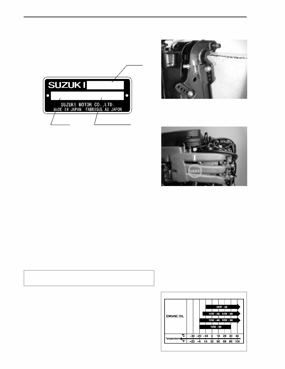
1-3 GENERAL INFORMATION IDENTIFICATION NUMBER LOCATION MODEL PRE-FIX SERIAL NUMBER The MODEL, PRE-FIX and SERIAL NUMBER of motor are stamped on a plate attached to the clamp bracket. Example FUEL AND OIL GASOLINE RECOMMENDATION Suzuki highly recommends that you use alcohol - free un- leaded gasoline with a minimum pump octane rating of 87 (R+M / 2 method) or 91 (Research method). However, blends of unleaded gasoline and alcohol with equivalent octane con- tent may be used. Allowable maximum blend of a single additive (not combina- tion) : 5% Methanol, 10% Ethanol, 15% MTBE B If leaded gasoline is used, engine damage may re- sult. ENGINE OIL Use only oils that are rated SE, SF, SG, SH, or SJ under the API (American Petroleum Institute) classification system. The viscosity rating should be SAE 10W-40. If an SAE 10W-40 motor oil is not available, select an alterna- tive according to the chart at right. MODEL PRE-FIX SERIAL NUMBER DF 50 05001F–XXXXXX ENGINE SERIAL NUMBER A second engine serial number plate is pressed into a boss on the cylinder block .
GENERAL INFORMATION 1-4 ENGINE BREAK-IN The first 10 hours are critically important to ensure correct running of either a brand new motor or a motor that has been reconditioned or rebuilt. How the motor is operated during this time will have direct bearing on its life span and long-term durability. Break-in period : 10 hours WARM-UP RECOMMENDATION Allow sufficient idling time (more than 5 minutes) for the en- gine to warm up after cold engine starting . THROTTLE RECOMMENDATION NOTE: Avoid maintaining a constant engine speed for an extended period at any time during the engine break-in by varying the throttle position occasionally. 1. FIRST 2 HOURS For first 15 minutes, operate the engine in-gear at idling speed. During the remaining 1 hour and 45 minutes, operate the engine in-gear at less than 1/2 (half) throttle (3000 r/min). NOTE: The throttle may be briefly opened beyond the recommended setting to plane the boat, but must be reduced to the recom- mended setting immediately after planning. 2. NEXT 1 HOUR Operate the engine in-gear at less than 3/4 (three-quar- ter) throttle (4000 r/min). 3. LAST 7 HOURS Operate the engine in-gear at desired engine speed. However, do not operate continuously at full throttle for more than 5 minutes.
1-5 GENERAL INFORMATION PROPELLERS An outboard motor is designed to develop its rated power within a specified engine speed range. The maximum rated power delivered by the DF40 / 50 T models is shown below. Blade × Diam. (in.) × Pitch (in.) 3 × 11- 1/2 × 9 (S900) 3 × 11- 1/2 × 10 (S1000) 3 × 11- 1/2 × 11 (S1100) 3 × 11- 5/8 × 12 (S1200) 3 × 11- 1/2 × 13 (S1301, SS1300) 3 × 11- 3/8 × 14 (S1400, SS1400) 3 × 11- 1/4 × 15 (S1500) 3 × 11- 1/8 × 16 (S1600, SS1600) 3 × 11 × 17 (S1700) If the standard propeller fails to meet the above requirement, use another pitch propeller to hold the engine speed within the range specified above. Propeller selection chart Recommended full throttle speed range DF40T 5200-5800 r / min DF50T 5900-6500 r / min
You're Reading a Preview
What's Included?
Lifetime Access
Fast Download Speeds
Online & Offline Access
Access PDF Contents & Bookmarks
Full Search Facility
Print one or all pages of your manual
$32.99
SUZUKI OUTBOARD DF40 DF50 Marine BOAT Service Repair Manual
SUZUKI OUTBOARD DF40 DF50 MARINE BOAT WORKSHOP SERVICE REPAIR MANUAL
This manual is compatible with the following computer operating systems:
All Windows versions
All Mac versions
You need the Adobe Acrobat Reader to view the document as the manual is in PDF format. If your computer doesn't have this application, you can download and install it for free from the Adobe Acrobat website.
As this manual is coming to you in PDF format, you need to extract the file before use by using extraction software. If your computer doesn't have this application, you can download and install it for free from a reliable website.
File size: 30 MB
This manual is presented for you in electronic format. You can just print out the page you need then dispose of it when you have completed your task. This manual has detailed illustrations as well as step by step written instructions with the necessary diagrams or pictures. These manuals are your number one source for repair and service information and specifically written for the do-it-yourself as well as the experienced mechanics worldwide used to use this factory manual to fix your vehicle. Using this repair manual is an inexpensive way to keep your machine working properly. It is this level of detail, along with illustrated, that guide the reader through each service, repair, and maintenance procedure.
Engine covered:
815 cc 4-stroke 3-cylinder DOHC
Contents:
Foreward
General Information
Maintenance
Engine Control System
Ignition System
Electronic Fuel Injection System
Caution System
Self-Diagnostic System
Fail-Safe System
Inspection
Troubleshooting
Removal / Installation
Battery Charging System
Electric Starter System
Fuel System
Intake Manifold Assembly
Power Unit
Oil Pump / Case
Timing Chain / Tensioner
Cylinder Head Assembly
Cylinder / Crankshaft / Piston
Thermostat
Engine Lubrication System
Mid Unit
Lower Unit
Wiring Diagram
Wire Routing
Fuel / Water Hose Routing
Recently Viewed
5,521,897Happy Clients
2,594,462eManuals
1,120,453Trusted Sellers
15Years in Business
Price:
Actual Price:
SUZUKI OUTBOARD DF40 DF50 Marine BOAT Service Repair Manual









 Lifetime Access




