

Suzuki Outboard Motor DF25 DF30 4 Stroke Service Repair Manual
What's Included?
Fast Download Speeds
Online & Offline Access
Access PDF Contents & Bookmarks
Full Search Facility
Print one or all pages of your manual

Chapter 1: General Information
Chapter 2: Tools and Techniques
Chapter 3: Troubleshooting and Testing
Chapter 4: Lubrication, Maintenance and Tune-Up
Chapter 5: Synchronization and Adjustment
Chapter 6: Fuel System
Chapter 7: Electrical and Ignition
Chapter 8: Power Head
Chapter 9: Gearcase
Chapter 10: Manual Start
Chapter 11: Hydraulic Trim and Midsection
Chapter 12: Remote Control
Chapter 13 Index
Chapter 14 Wiring Diagrams
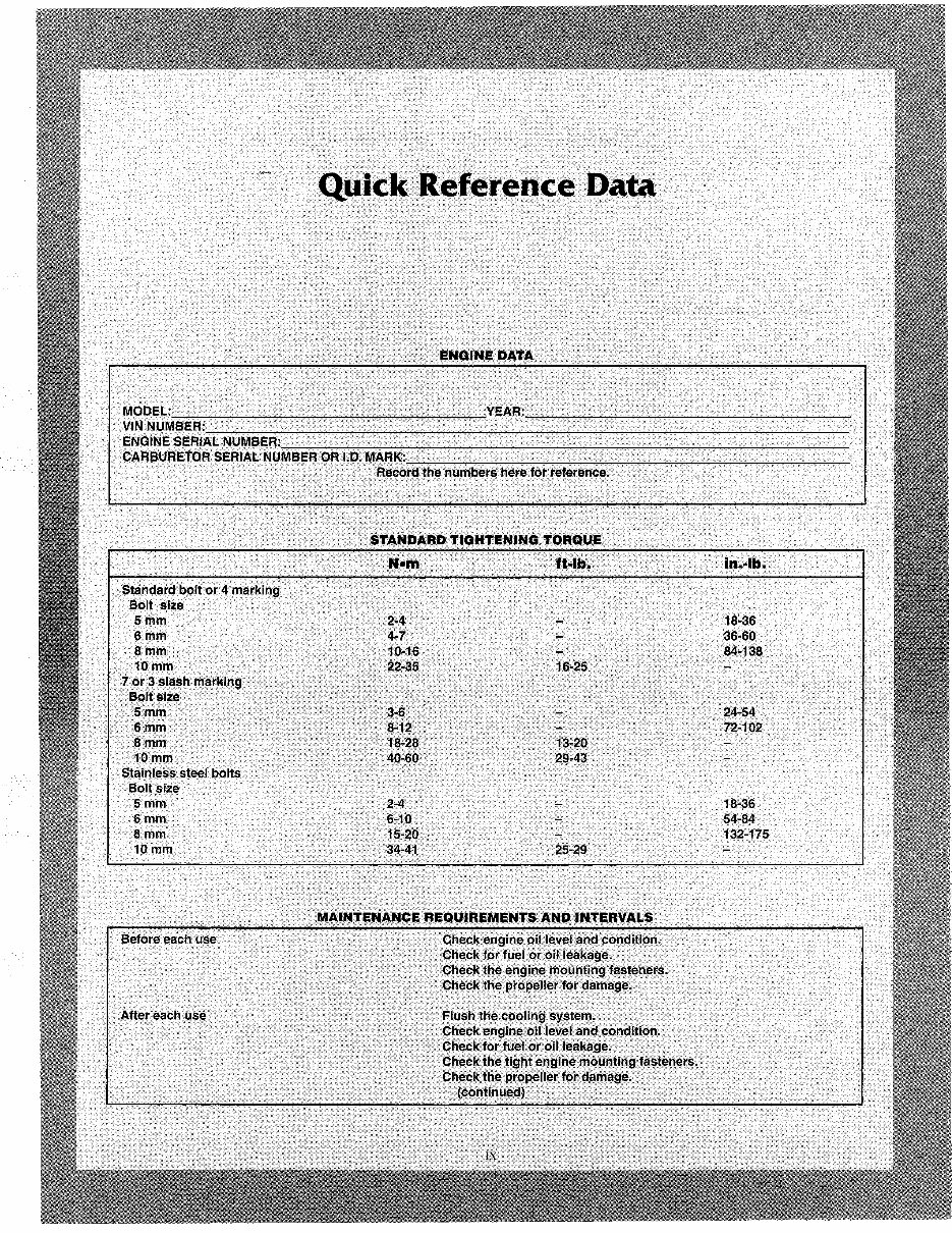
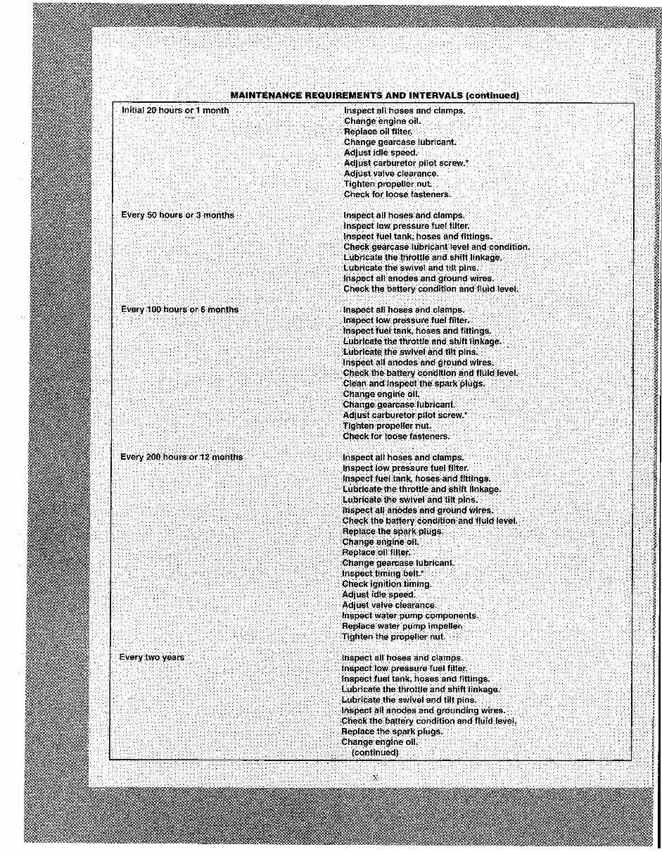
MAINTENANCE REQUIREI\iIENTSAND INTERVALS (continued)
Initial 20 hOl,lr~ or.1 month
Every 50 hc;>urs or 3. mO!lths
Every 200 houfsor.12 montl'ls.
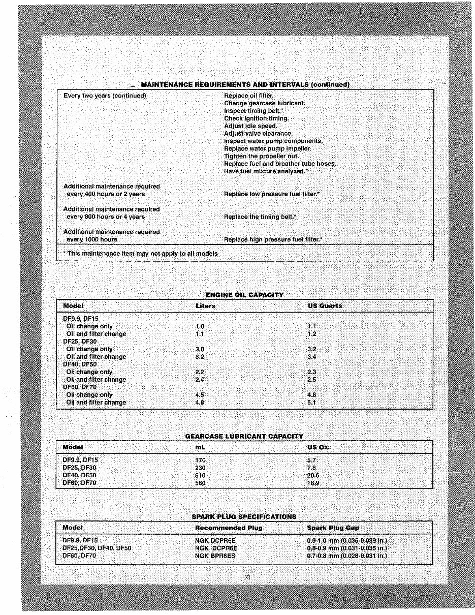
Every two years.
Inspect all hoses and clamps.
Changee!1gine oil.
Replace. QiI.fllter.
Chang~ gearcasell,lbricant.
Adjustidte speed.
Adjustcarburetor pilot screw.*
Adjust valvecl.earance.
Tighten propeller nut.
Check for loose fasteners.
Inspect all hosesand.clamps.
InsPect Iow pressure fuel.filter;
InspectJueltank, hoses and. fittings •
.Cbeckgearc!,8e lubricant level and C9n(ntion~
.Lubricate. the throttle and shift linkage.
Lubrica.te the.swivel and tUtpins.
· Inspect al.1 anodes and ground wires:
Ch.eck the battery cQndition andflu!d level.
Inspect all hOses and clamps.··
Inspect low pressure fuel. filter.·
Inspect fuel tank, hoses and . fittings.
ll,lbric.ate the throttle and shift linkage •.
Lubricate the swivel andtilf pin~. .
Ihspectall.anodes. and groutyd. wires.
· C:he~~ the baUerycond!tion and fhlidle.vel:
cte~mand inspectthe spark plugs.
Chan9~engine QiI. .
c:;hangegearcase JUt)rlcant,
Ad) liSt carburetorpilof screw. *
Tighten propeller nut.
·Check for loose fa.steners.
Im~pect all hoses. and ~Iamps.
.Inspect low pj'essurefuelfU~er.
Inspectfue.1 tank; hoses and fittings.
Lubricate the tl)rotfle and shift linkage.
L.ubrlcate .the SWiV~.1 and tilt pins;
Inspect aif.anodesand ground wires.
Che~Kt~e~attery conditicm and fluid level •.
~eplace the.spatkplogs, ..
· Cnangeengine 011.·
Replace oil.fnter; ..
Cl)aflge Qea.rcase . lubricant
.lnsPecttfrnin:9belt;*
CheCk ignition timing.
Adj~.Il~t .idle speed.
Adjust valve clearance.
Inspect water pump components.
Replacewater pump impeller;
Tighten the ptopeflernut.
Inspect all hoses and clamps.
Inspect Jow pressure fuel fiiter.
Inspect fuel tank; hoses and fittings.
L,ubricate the throttle and sh ift linkage.
lu~ricate the .swivel and tilt pins.
. Insp~ctan anodes and grounding .. wires.
Check ttJe battery condition and fluid level.
Replace the spark plugs.
Change engine oiL
(continUed)

Chapter One
General Information
This detailed, comprehensive manual con-
tains complete information on maintenance,
tune-up, repair and overhaul. Hundreds of pho-
tos and drawings guide you through every step-
by -step procedure.
Troubleshooting, tune-up, maintenance and
repair are not difficult if you know what tools
and equipment to use and what to do. Anyone
not afraid to get their hands dirty, of average
intelligence and with some mechanical ability,
can perform most of the procedures in this book.
See Chapter Two for more information on tools
and techniques.
A shop manual is a reference. You want to be
able to find information fast. Books are
designed with you in mind. All chapters are
thumb tabbed and important items are indexed
at the end of the book. All procedures, tables,
photos, etc., in this manual assume that the
reader may be working on the machine or using
this manual for the first time.
Keep this book handy in your tool box. It will
help you to better understand how your machine
runs, lower repair and maintenance costs and
generally increase your enjoyment of your ma-
rine equipment.
MANUAL ORGANIZATION
This chapter provides general information
useful to marine owners and mechanics.
Chapter Two discusses the tools and tech-
niques for preventive maintenance, trou-
bleshooting and repair.
Chapter Three describes typical equipment
problems and provides logical troubleshooting
procedures.
Following chapters describe specific systems,
providing disassembly, repair, assembly and ad-
justment procedures in simple step- by- step
form. Specifications concerning a specific sys-
tem are included at the end of the appropriate
chapter.
NOTES, CAUTIONS
AND WARNINGS
The terms NOTE, CAUTION and WARN-
ING have specific meanings in this manual. A
NOTE provides additional information to make
a step or procedure easier or clearer. Disregard-
ing a NOTE could cause inconvenience, but
would not cause damage or personal injury.

CHAPTER ONE
A CAUTION emphasizes areas where equip-
ment damage could result. Disregarding a CAU-
TION could cause permanent mechanical
damage; however, personal injury is unlikely.
A WARNING emphasizes areas where per-
sonal injury or even death could result from
negligence. Mechanical damage may also occur.
WARNINGS are to be taken seriously. In some
cases, serious injury or death has resulted from
disregarding similar warnings.
TORQUE SPECIFICATIONS
Torque specifications throughout this manual
are given in foot-pounds (ft.-lb.) and either Wew-
ton meters (N.m) or meter-kilograms (mkg).
Newton meters are being adopted in place of
meter-kilograms in accordance with the Intema-
tional Modernized Metric System. Existing
torque wrenches calibrated in meter-kilograms
can be used by perfoming a simple conversion:
move the decimal point one place to the right.
For example, 4.7 mkg = 47 N.m. This conversion
is accurate enough for mechanics' use even
though the exact mathematical conversion is 3.5
mkg = 34.3 N.m.
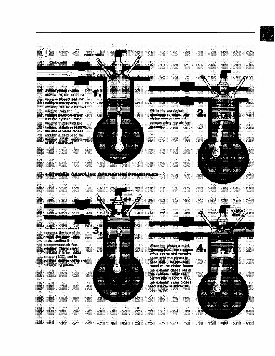
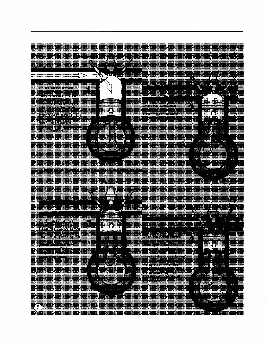
ENGINE OPERATION
All marine engines, whether 2- or 4-stroke,
gasoline or diesel, operate on the Otto cycle of
intake, compression, power and exhaust phases.
A 4- stroke engine requires two crankshaft
revolutions (4 strokes of the piston) to complete
the Otto cycle. Figure I shows gasoline 4-stroke
engine operation. Figure 2 shows diesel 4-stroke
engine operation.
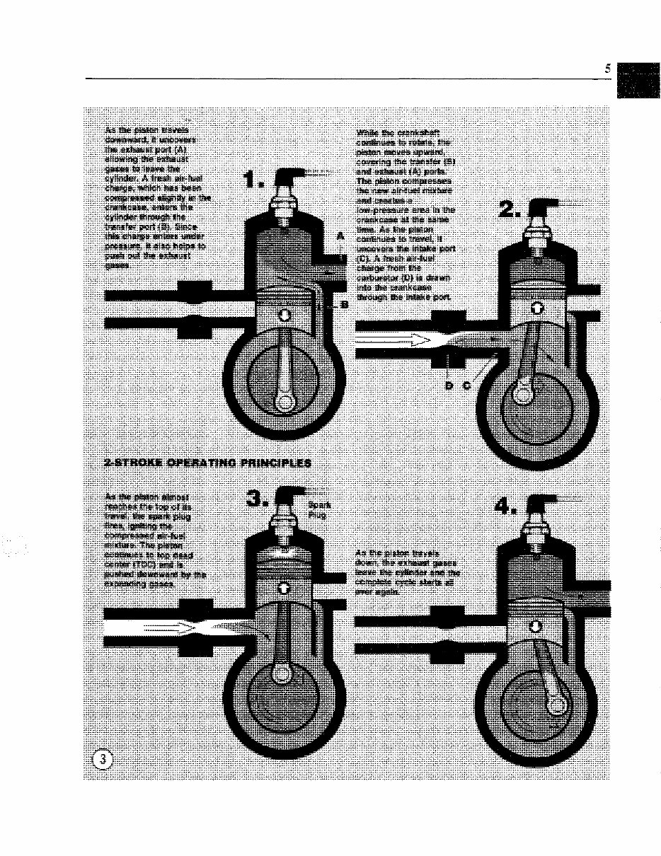
2-stroke Cycle
A 2-stroke engine requires only I crankshaft
revolution (2 strokes of the piston) to complete
the Otto cycle. Figure 3 shows gasoline 2-stroke
engine operation. Although diesel 2-strokes ex-
ist, they are not commonly used in light marine
applications.
FASTENERS
The material and design of the various fasten-
ers used on marine equipment are not arrived at
by chance or accident. Fastener design deter-
mines the type of tool required to work with the
fastener. Fastener material is carefully selected
to decrease the possibility of physical failure or
corrosion. See Cah~ani Corrosiolz in this chap-
ter for more information on marine materials.
Threads
Nuts, bolts and screws are manufactured in a
wide range of thread patterns. To join a nutand
bolt, the diameter of the bolt and the diameter of
the hole in the nut must be the same. It is just as
impoflant that the threads on both be properly
matched.
The best way to deternine if the threads on
two fasteners are matched is to turn the nut on
the bolt (or the bolt into the threaded hole in a
piece of equipment) with fingers only. Be sure
both pieces are clean. If much force is required,
check the thread condition on each fastener. If
the thread condition is good but the fasteners
jam, the threads are not compatible.
Four important specifications describe every
thread:
a. Diameter.
b. Threads per inch.
c. Thread pattern.
d. Thread direction.
Figure 4 shows the first two specifications.
Thread pattern is more subtle. Italian and British
GENERAL INFORMATION 3
4 CHAPTER ONE
GENERAL INFORMATION 5 5
You're Reading a Preview
What's Included?
Fast Download Speeds
Online & Offline Access
Access PDF Contents & Bookmarks
Full Search Facility
Print one or all pages of your manual
$30.99
Viewed 10 Times Today


Secure transaction
What's Included?
Fast Download Speeds
Online & Offline Access
Access PDF Contents & Bookmarks
Full Search Facility
Print one or all pages of your manual
$30.99
- Covers Models:
- DF25
- DF30
- Y MODEL
- K3 MODEL
- This is the most complete service repair manual for Suzuki Outboard Motor DF25 DF30 4 Stroke in PDF format.
- This Service Repair Manual has easy-to-read text sections with high quality diagrams and instructions.
- Service Repair Manual Covers:
- GENERAL INFORMATION
- PERIODIC MAINTENANCE
- ENGINE CONTROL SYSTEM
- ENGINE ELECTRICAL
- FUEL SYSTEM
- RECOIL STARTER
- POWER UNIT
- MID UNIT
- POWER TRIM AND TILT
- LOWER UNIT
- WIRE / HOSE ROUTING
- DF25/30 K3 (03) MODEL
- File Format: PDF
- Printable: Yes
- Compatible: All Versions of Windows & Mac
- Language: English
- Requirements: Adobe Reader
- Instant means there will be no shipping cost or waiting for a paper or CD to arrive in the mail.
- You will get this manual immediately after payment!!
- Have any questions please contact me.


