

VERADO 200 225 250 275 HP OUTBOARD Service Repair Manual
What's Included?
Fast Download Speeds
Online & Offline Access
Access PDF Contents & Bookmarks
Full Search Facility
Print one or all pages of your manual
Page iii
Service Manual Outline
1 - Important Information
A - Master Specifications
B - Maintenance
C - General Information
D - Outboard Motor Installation
2 - Electrical
A - Ignition
B - Charging and Starting System
C - Timing, Synchronizing and Adjusting
D - Digital Throttle and Shift
3 - Fuel System
A - Fuel System Operation
B - Troubleshooting and Diagnostics
C - Service Procedures
D - Emissions
4 - Powerhead
A - Cylinder Block/Crankcase
B - Cylinder Head
C - Lubrication
5 - Mid-Section
A - Pedestal/Mount Cradle and Driveshaft Housing
B - Adapter Plate
C - Power Trim
6 - Lower Unit
A - Right Hand Rotation
B - Left Hand Rotation
7 - Attachments
A - Attachments
8 - Power Steering
A - Power Steering
9 - Colored Wire Diagrams
A - Colored Wire Diagrams
Important Information
1
Electrical
2
Fuel System
3
Powerhead
4
Mid-Section
5
Lower Unit
6
Attachments
7
Power Steering
8
Colored Wire Diagrams
9
Page i
Notice to Users of This Manual
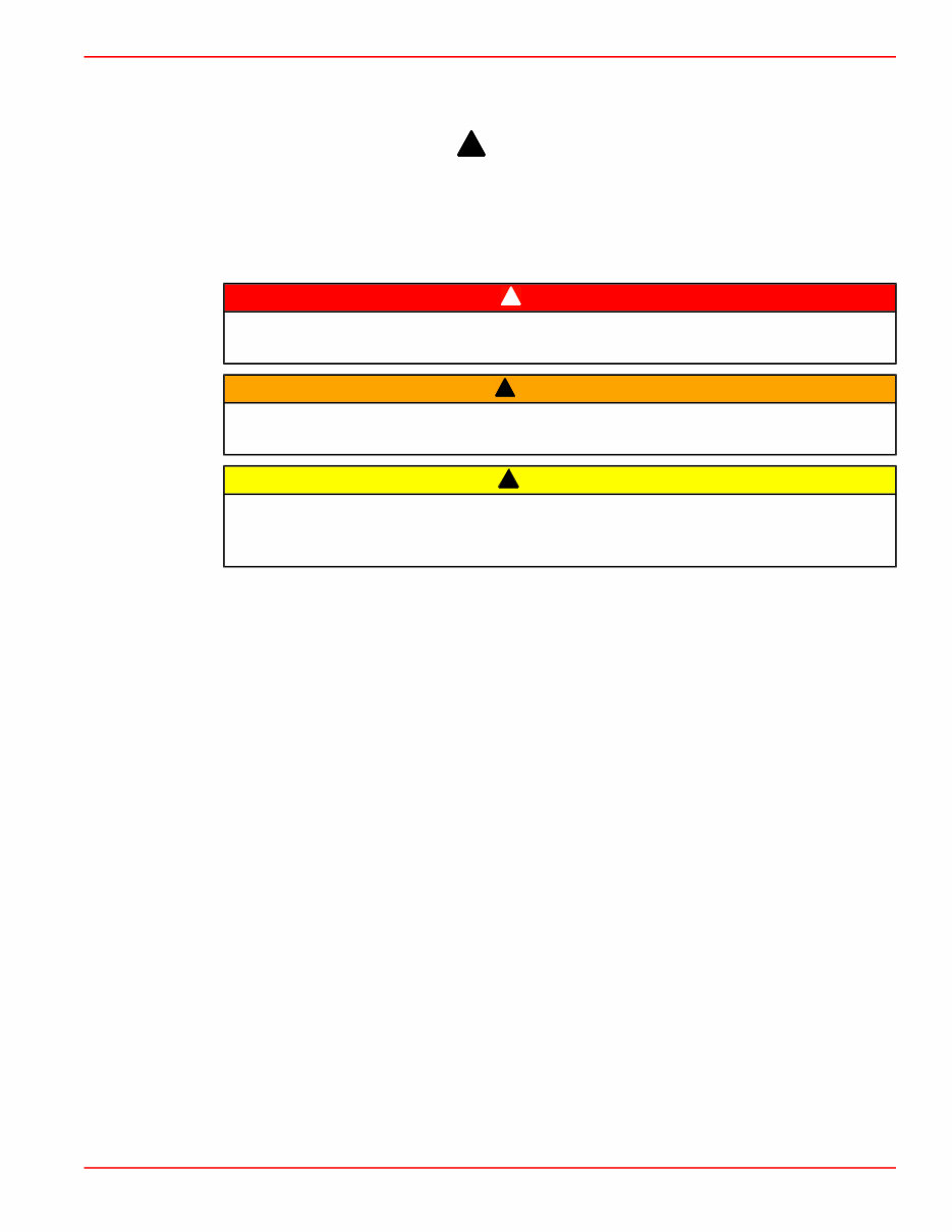
Throughout this publication, Dangers, Warnings and Cautions (accompanied by the
International HAZARD Symbol
!
) are used to alert the mechanic to special instructions
concerning a particular service or operation that may be hazardous if performed incorrectly
or carelessly. OBSERVE THEM CAREFULLY!
These safety alerts alone cannot eliminate the hazards that they signal. Strict compliance
to these special instructions when performing the service, plus common sense operation,
are major accident prevention measures.
! DANGER
DANGER - indicates an imminently hazardous situation that, if not avoided, will result in
death or serious injury.
! WARNING
WARNING - indicates a potentially hazardous situation that, if not avoided, could result
in death or serious injury.
! CAUTION
CAUTION - indicates a potentially hazardous situation that, if not avoided, may result in
minor or moderate injury or property damage. It may also be used to alert against unsafe
practices.
This service manual has been written and published by the Service Department of Mercury
Marine to aid our dealers’ mechanics and company service personnel when servicing the
products described herein. We reserve the right to make changes to this manual without
prior notification.
© 2004, Mercury Marine
Mercury, Mercury Marine, MerCruiser, Mercury MerCruiser, Mercury Racing, Mercury
Precision Parts, Mercury Propellers, Mariner, Quicksilver, #1 On The Water, Alpha, Bravo,
Pro Max, OptiMax, Sport-Jet, K-Planes, MerCathode, RideGuide, SmartCraft, Zero Effort,
M with Waves logo, Mercury with Waves logo, and SmartCraft logo are all registered
trademarks of Brunswick Corporation. Mercury Product Protection logo is a registered
service mark of Brunswick Corporation.
It is assumed that these personnel are familiar with marine product servicing procedures.
Furthermore, it is assumed that they have been trained in the recommended service
procedures of Mercury Marine Power Products, including the use of mechanics’ common
hand tools and the special Mercury Marine or recommended tools from other suppliers.
We could not possibly know of and advise the marine trade of all conceivable procedures
and of the possible hazards and/or results of each method. Therefore, anyone who uses
a service procedure and/or tool, which is not recommended by the manufacturer, first must
completely satisfy himself that neither his nor the products safety will be endangered.
All information, illustrations and specifications contained in this manual are based on the
latest product information available at the time of publication. As required, revisions to this
manual will be sent to all dealers contracted by us to sell and/or service these products.
Refer to dealer service bulletins, operation maintenance and warranty manuals and
installation manuals for other pertinent information concerning the products described in
this manual.
Page ii
Precautions
It should be kept in mind, while working on the product, that the electrical and ignition
systems are capable of violent and damaging short circuits or severe electrical shocks.
When performing any work where electrical terminals could possibly be grounded or
touched by the mechanic, the battery cables should be disconnected at the battery.
Any time the intake or exhaust openings are exposed during service they should be
covered to protect against accidental entrance of foreign material which could enter the
cylinders and cause extensive internal damage when the engine is started.
It is important to note, during any maintenance procedure replacement fasteners must have
the same measurements and strength as those removed. Numbers on the heads of the
metric bolts and on the surfaces of metric nuts indicate their strength. American bolts use
radial lines for this purpose, while most American nuts do not have strength markings.
Mismatched or incorrect fasteners can result in damage or malfunction, or possibly
personal injury. Therefore, fasteners removed should be saved for reuse in the same
locations whenever possible. Where the fasteners are not satisfactory for reuse, care
should be taken to select a replacement that matches the original.
Replacement Parts
Use of parts other than the recommended service replacement parts, will void the warranty
on those parts that are damaged as a result.
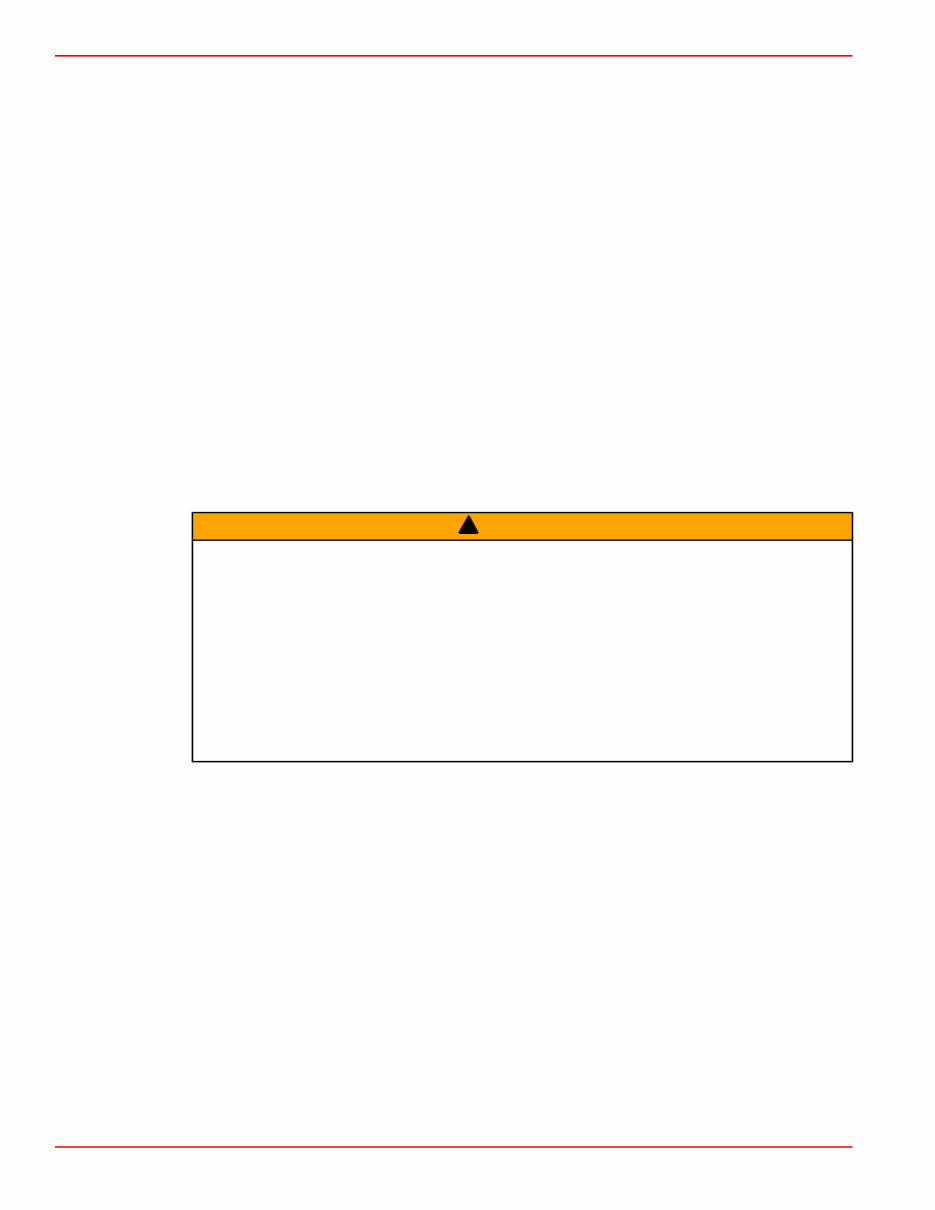
! WARNING
Electrical, ignition and fuel system components on Mercury Marine Power Products are
designed and manufactured to comply with U.S. Coast Guard Rules and Regulations to
minimize risks of fire or explosion.
Use of replacement electrical, ignition or fuel system components, which do not comply
to these rules and regulations, could result in a fire or explosion hazard and should be
avoided.
When servicing the electrical, ignition and fuel systems, it is extremely important that all
components are properly installed and tightened. If not, any electrical or ignition
component opening would permit sparks to ignite fuel vapors from fuel system leaks, if
they existed.
Cleanliness and Care of Product
A Mercury Marine Power Product is a combination of many machined, honed, polished and
lapped surfaces with tolerances that are measured in the ten thousands of an inch/mm.
When any product component is serviced, care and cleanliness are important. Throughout
this manual, it should be understood that proper cleaning and protection of machined
surfaces and friction areas is a part of the repair procedure. This is considered standard
shop practice even if not specifically stated.
Whenever components are removed for service, they should be retained in order. At the
time of installation, they should be installed in the same locations and with the same mating
surfaces as when removed.
Personnel should not work on or under an engine that is suspended. Engines should be
attached to work stands, or lowered to ground as soon as possible.

Master Specifications
90-896580100 JULY 2004 Page 1A-1
1
A
Important Information
Section 1A - Master Specifications
Table of Contents
200/225/250/275 Verado Master Specifications
.........................................................................1A-2
General Specifications..............................1A-2
Fuel System Specifications.......................1A-2
Ignition Specifications...............................1A-3
Charging and Starting Specifications........1A-3
Cylinder Head Specifications....................1A-4
Cylinder Block/Crankcase Specifications
..................................................................1A-5
Power Trim Specifications........................1A-5
Oil System Specifications.........................1A-6
Gear Housing Specifications (Standard
Rotation)...................................................1A-6
Gear Housing Specifications (Counter
Rotation)...................................................1A-6
Power Steering Specifications..................1A-6
Propeller Chart.................................................1A-7
Mercury/Mariner 200 (6 Cyl., 4 Stroke).....1A-7
Mercury/Mariner 225 (6 Cyl., 4 Stroke).....1A-8
Mercury/Mariner 250 (6 Cyl., 4 Stroke)...1A-10
Mercury/Mariner 275 (6 Cyl., 4 Stroke)...1A-12

Master Specifications
Page 1A-2 90-896580100 JULY 2004
200/225/250/275 Verado Master Specifications
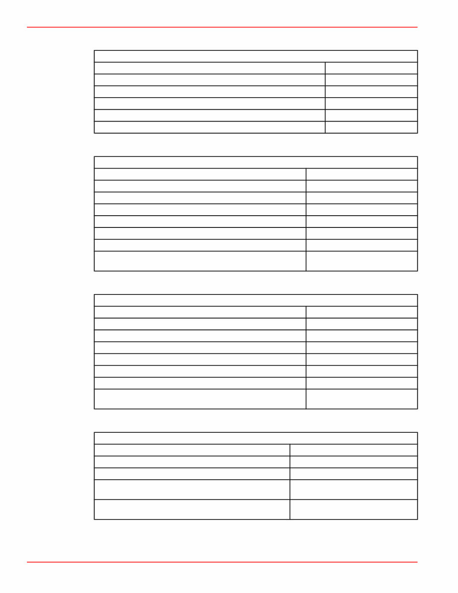
General Specifications
Model Specifications
Kilowatts (Horsepower)
149 kw (200 HP)
168 kw (225 HP)
186 kw (250 HP)
205 kw (275 HP)
Weight
50.8 cm (20 in.) 293 kg (645 lbs.)
63.5 cm (25 in.) 299 kg (659 lbs.)
76.2 cm (30 in.) 307 kg (677 lbs.)
Displacement (All Hp) 2.6L (158.5 cu. in.)
RPM
Idle 550 ± 50 RPM
WOT 5800 - 6400 RPM
Induction System
SmartCraft DTS® electronic throttle, intercooled supercharged aspiration with
electronic boost pressure control
Fuel System Computer controlled sequential multi-port Electronic Fuel Injection
Ignition System SmartCraft Propulsion Control Module (PCM) 03 digital inductive
Charging System Regulated belt driven 70 amp alternator
Exhaust System Through prop
Cooling System Water cooled - thermostat with pressure control
Lubrication System
Integrated dry sump 7 Liters (7.4 qts.)
Engine Control System SmartCraft PCM 03 Digital Throttle and Shift (DTS)
Trim System SmartCraft programmable
Maximum Tilt Range 73° (-6° to 67°)
Maximum Trim Range 20° (-6° to 14°)
Steering System Electric - Hydraulic Power Steering with integral hydraulic cylinder
Fuel System Specifications
Fuel System Specifications
Type of fuel
149 kw (200 hp), 168 kw (225 hp), 186 kw (250 hp)
Automotive unleaded with a minimum pump posted
octane rating of 87 (90 RON)
205 kw (275 hp)
Automotive unleaded with a minimum pump posted
octane rating of 91 (96 RON)
Approximate fuel pressure @ idle 279 - 289 kPa (40 - 42 psi)
Fuel filtration
Fuel inlet water separator 2 Microns
High pressure 20 Microns

Master Specifications
90-896580100 JULY 2004 Page 1A-3
Ignition Specifications
Ignition Specifications
Full Throttle RPM (All Models) 5800 - 6400
Idle RPM (All Models) 550
Ignition Type Digital Inductive
Spark Plug Type NGK ILFR6G
Spark Plug Gap 0.8 mm (0.031 in.)
Spark Plug Hex Size 16 mm
Spark Plug Torque 27.5 Nm (19 lb. ft.)
Spark Plug Hole Size 14 mm
Firing Order 1-3-5-6-4-2
Ignition Timing @ Idle Not Adjustable; Controlled by PCM
Ignition Timing @ WOT Not Adjustable; Controlled by PCM
PCM Over Speed Limiter Activates @ 6500 RPM
Charging and Starting Specifications
Charging and Starting Specifications
Alternator Output (Regulated)
Output @ Battery (@ 1000 RPM) 37 - 44 Amperes
Output @ Battery (@ 3000 RPM) 53 - 69 Amperes
Output @ Alternator (@ 1000 RPM) 48 - 54 Amperes
Output @ Alternator (@ 3000 RPM) 65 - 72 Amperes
Voltage Set Point 14.5 +/- 0.25 Volts
Regulator Current Draw
1.
Ignition Switch "OFF" (maximum) 1.0 mA
Ignition Switch "ON" 350 mA
Starter Draw (Under Load) 160 Amperes
Starter Draw (No Load) 60 Amperes
Minimum Brush Length 65.4 mm (0.25 in.)
Battery Rating
Marine Cranking Amperes (minimum) 1000
Cold Cranking Amperes (minimum) 800
Ampere Hour (Ah) (minimum) 180
1. All model alternator specifications require an amperage draw of less than 1.0 mA with the ignition key in the "OFF" position and an
amperage draw of not more than 350.0 mA with key in the "ON" position.

Master Specifications
Page 1A-4 90-896580100 JULY 2004
Cylinder Head Specifications
Cylinder Head Specifications
Maximum deck warp 0.075 mm (0.003)
Number of valves 24
Number of valves per cylinder 4
Number of cams 2
Cam bearing journal (intake and exhaust) 28.95 mm (1.1398 in.)
Camshaft bearing cap ID 29.000 - 29.021 mm (1.1417 - 1.1425 in. )
Cam lobe
Intake 42.50 mm (1.6732 in.)
Exhaust 43.55 mm 1.7145 in.)
Valve lash
Intake 0.150 - 0.230 mm (0.0059 - 0.009)
Exhaust 0.350 - 0.430 mm (0.0137 - 0.0169 in.)
Valve seat angles 30°, 45°, 60°
Valve spring free length 48.77 mm (1.920 in.)
Valve outside diameter
Intake 32.0 ± 0.15 mm (1.259 ± 0.0059 in.)
Exhaust 27.2 mm ± 0.190 (1.0708 ± 0.0059 in.)
Valve face width (intake and exhaust) 2.25 mm (0.0886 in.)
Valve margin
Intake 0.75 mm (0.0295 in.)
Exhaust 0.65 mm (0.0256 in.)
Valve guide bore ID (intake and exhaust) 6.00 - 6.016mm (0.2362 - 0.2368 in.)
Valve stem diameter
Intake 5.97 mm (0.235 in.)
Exhaust 5.96 mm (0.2346 in.)
Valve stem run-out (maximum) 0.038 mm (0.0015 in.)
Valve stem to valve guide clearance
Intake 0.03 - 0.046 mm (0.0011 - 0.0018 in.)
Exhaust 0.04 - 0.056 mm (0.0015 - 0.0022 in.)
Valve seat contact width (intake and exhaust) 2.25 mm (0.0886 in.)

Master Specifications
90-896580100 JULY 2004 Page 1A-5
Cylinder Block/Crankcase Specifications
Cylinder Block/Crankcase Specifications
Number of cylinders 6
Displacement 2.6 Liters (158.6 CID)
Compression ratio 8.25:1
Standard bore 82.00 mm (3.228 in.)
Stroke 82.0 mm (3.228 in.)
Cylinder bore maximum taper (service) 0.0762 mm (0.003 in.)
Cylinder bore maximum out of round (service) 0.0762 mm (0.003 in.)
Cylinder block main bearing 65.997 - 66.013 mm (2.5982 - 2.5989 in.)
Crankshaft main bearing journal 59.985 - 60.001 mm (2.3616 - 2.3622 in.)
Crankshaft pin journal 49.982 - 50.0 mm (1.9678 - 1.968 in.)
Crankshaft end play 0.08 - 0.19 mm mm (0.003 - 0.007 in.)
Crankshaft run out 0.05 mm (0.002 in.)
Crankshaft main bearing oil clearance (without expansion) 0.014 - 0.042 mm (0.0005 - 0.0016 in.)
Crankshaft pin bearing oil clearance (without expansion) 0.020 - 0.050 mm (0.0008 - 0.0019 in.)
Connecting rod wrist pin bore diameter 22.005 - 22.014 mm (0.8663 - 0.8666 in.)
Connecting rod crankshaft pin diameter 53.000 - 53.018 mm (2.0866 - 2.0873 in.)
Piston skirt standard diameter 81.975 mm (3.2273 in.)
Piston wrist pin bore diameter 22.004 - 22.011 mm (0.8662 - 0.8665 in.)
Wrist pin diameter 21.997 - 22.000 mm (0.8660 - 0.8661 in.)
Top ring grove width 1.25 mm (0.049 in.)
Second ring grove width 1.25 mm (0.049 in.)
Third ring grove width 2.05 mm (0.081 in.)
Top ring thickness 1.19 mm (0.047 in.)
Second ring thickness 1.19 mm (0.047 in.)
Third ring thickness 1.98 mm (0.078 in.)
Top ring side clearance 0.04 - 0.08 mm (0.001 - 0.003 in.)
Second ring side clearance 0.04 - 0.08 mm (0.001 - 0.003 in.)
Third ring side clearance 0.05 - 0.17 mm (0.002 - 0.006
Top ring end gap 0.27 - 0.42 mm (0.010 - 0.016 in.)
Second ring end gap 0.42 - 0.62 mm (0.016 - 0.024 in.)
Oil ring end gap 0.2 - 0.7 mm (0.007 - 0.027 in.)
Power Trim Specifications
Power Trim Specifications
Trim up circuit pressure, maximum 18,270 - 28,960 kPa (2650 - 4200 psi)
Trim down circuit pressure 1255 - 2765 kPa (182 - 401 psi)
System fluid
Power Trim and Steering Fluid or Automatic Transmission Fluid (ATF)
(Type Dexron III)
Master Specifications
Page 1A-6 90-896580100 JULY 2004
Oil System Specifications
Oil System Specifications
Engine Capacity Wet 7 liters (7.4 qts.)
Engine Capacity Dry 8 liters (8.4 qts.)
Oil Filter Part Number 35-883701K01
Oil Pressure (Minimum) @ 550 RPM 70 kPa (10 psi)
Oil Pressure (Minimum) @ 6000 RPM 220 kPa (32 psi)
IOM thermostat opening temperature 105 °C (221 °F)
Gear Housing Specifications (Standard Rotation)
Gear Housing Specifications (Standard Rotation)
Gear Ratio 1.85:1 (13/24 Teeth)
Gearcase Capacity 970 ml (32.8 fl.oz.)
Gear Lubricant Type Premium Gear Lubricant
Pinion Height 0.635 mm (0.025 in.)
Forward Gear Backlash 0.482 - 0.660 mm (0.019 - 0.026 in.)
Reverse Gear Backlash 1.27 - 1.47 mm (0.050 - 0.058 in.)
Water Pressure @ RPM 55 - 68.9 kPa (8 - 10 psi)
Gear Housing Pressure (without gear lubricant, 5 minutes without
leakage)
103.4 kPa (15 psi)
Gear Housing Specifications (Counter Rotation)
Gear Housing Specifications (Counter Rotation)
Gear Ratio 1.85:1 (13/24 Teeth)
Gearcase Capacity 970 ml (32.8 fl.oz.)
Gear Lubricant Type Premium Gear Lubricant
Pinion Height 0.635 mm (0.025 in.)
Forward Gear Backlash 0.482 - 0.660 mm (0.019 - 0.026 in.)
Reverse Gear Backlash 1.27 - 1.47 mm (0.050 - 0.058 in.)
Water Pressure @ RPM 55 - 68.9 kPa (8 - 10 psi)
Gear Housing Pressure (without gear lubricant, 5 minutes without
leakage)
103.4 kPa (15 psi)
Power Steering Specifications
Power Steering Specifications
Fluid Type SAE 0W-30 synthetic power steering fluid
Capacity Typical 1 - 2 liters (1 - 2 quarts)
Current Draw Shall not exceed 75 Amps
Steering Ratio (40 cc helm and single steering cylinder, lock to
lock)
4.1 turns
Steering Ratio (50 cc helm with dual steering cylinders, lock to
lock)
6.5 turns

Master Specifications
90-896580100 JULY 2004 Page 1A-7
Propeller Chart
Mercury/Mariner 200 (6 Cyl., 4 Stroke)
• Wide Open Throttle RPM: 5800 - 6400
• Recommended Transom Height: 50.8 cm (20 in.), 63.5 cm (25 in.), 76.2 cm (30 in.)
• Gear Reduction: 1.85:1
• Right Hand Rotation (RH), Left Hand Rotation (LH)
Diameter Pitch
No. of
Blades
Model Approx. Gross Boat Wgt.
Approx. Boat
Length
Speed Range
Propeller Part
Number
13.75 27 4 Trophy Plus
Up to952.54 Kg
(2100 lbs.)
Up to 6.4 m
(21 ft.)
120.70 - 136.8 km
(75 - 85 MPH)
48-825946A47
14.62 27 3 Tempest Plus
Up to952.54 Kg
(2100 lbs.)
Up to 6.4 m
(21 ft.)
120.70 - 136.8 km
(75 - 85 MPH)
48-825868A47
15.25 26 4 Bravo 1
861.83 - 997.7 Kg
(1900-2200 lbs.)
6.4 - 7.0 m
(21 - 23 ft.)
115.87 - 130.4 km
(72 - 81 MPH)
48-831914A45
(RH)
48-831913A45
(LH)
13.75 26 4 Trophy Plus
861.83 - 997.7 Kg
(1900-2200 lbs.)
6.4 - 7.0 m
(21 - 23 ft.)
115.87 - 130.4 km
(72 - 81 MPH)
48-825944A47
14.62 26 3 Tempest Plus
861.83 - 997.7 Kg
(1900-2200 lbs.)
6.4 - 7.0 m
(21 - 23 ft.)
115.87 - 130.4 km
(72 - 81 MPH)
48-825874A47
14.50 25 3 Mirage Plus
907.18 - 1043.26 Kg
(2000-2300 lbs.)
6.4 - 7.0 m
(21 - 23 ft.)
111.04 - 125.53 km
(69 - 78 MPH)
48-13706A46
(RH)
48-13707A46 (LH)
13.75 25 4 Trophy Plus
907.18 - 1043.26 Kg
(2000-2300 lbs.)
6.4 - 7.0 m
(21 - 23 ft.)
111.04 - 125.53 km
(69 - 78 MPH)
48-825942A47
14.62 25 3 Tempest Plus
907.18 - 1043.26 Kg
(2000-2300 lbs.)
6.4 - 7.0 m
(21 - 23 ft.)
111.04 - 125.53 km
(69 - 78 MPH)
48-825866A47
15.25 24 4 Bravo I
952.54 - 1088.62 Kg
(2100-2400 lbs.)
6.7 - 7.3 m
(22 - 24 ft.)
106.22 - 119.09 km
(66 - 74 MPH)
48-831912A45
(RH)
48-831911A45
(LH)
13.75 24 4 Trophy Plus
952.54 - 1088.62 Kg
(2100-2400 lbs.)
6.7 - 7.3 m
(22 - 24 ft.)
106.22 - 119.09 km
(66 - 74 MPH)
48-825940A47
14.62 24 3 Tempest Plus
952.54 - 1088.62 Kg
(2100-2400 lbs.)
6.7 - 7.3 m
(22 - 24 ft.)
106.22 - 119.09 km
(66 - 74 MPH)
48-825872A47
14.62 23 4 Revolution 4
997.90 - 1133.98 Kg
(2200-2500 lbs.)
6.7 - 7.3 m
(22 - 24 ft.)
101.39 - 114.26 km
(63 - 71 MPH)
48-857030A46
(RH)
48-857031A46
(LH)
13.75 23 4 Trophy Plus
997.90 - 1133.98 Kg
(2200-2500 lbs.)
6.7 - 7.3 m
(22 - 24 ft.)
101.39 - 114.26 km
(63 - 71 MPH)
48-825938A47
14.62 23 3 Tempest Plus
997.90 - 1133.98 Kg
(2200-2500 lbs.)
6.7 - 7.3 m
(22 - 24 ft.)
101.39 - 114.26 km
(63 - 71 MPH)
48-825864A47
14.63 23 3 Mirage Plus
997.90 - 1133.98 Kg
(2200-2500 lbs.)
6.7 - 7.3 m
(22 - 24 ft.)
101.39 - 114.26 km
(63 - 71 MPH)
48-13704A46
(RH)
48-13705A46 (LH)
13.25 23 5 High Five
997.90 - 1133.98 Kg
(2200-2500 lbs.)
6.7 - 7.3 m
(22 - 24 ft.)
101.39 - 114.26 km
(63 - 71 MPH)
48-815762A46
You're Reading a Preview
What's Included?
Fast Download Speeds
Online & Offline Access
Access PDF Contents & Bookmarks
Full Search Facility
Print one or all pages of your manual
$46.99
$61.99
Viewed 39 Times Today


Secure transaction
What's Included?
Fast Download Speeds
Online & Offline Access
Access PDF Contents & Bookmarks
Full Search Facility
Print one or all pages of your manual
$46.99
$61.99
This is a comprehensive service repair manual for the MERCURY MARINER VERADO 200 225 250 275 HP OUTBOARD engines, covering the following engine models:
- MERCURY MARINER VERADO 200HP (6-CYLINDER, 4-STROKE)
- MERCURY MARINER VERADO 225HP (6-CYLINDER, 4-STROKE)
- MERCURY MARINER VERADO 250HP (6-CYLINDER, 4-STROKE)
- MERCURY MARINER VERADO 275HP (6-CYLINDER, 4-STROKE)
The manual covers a 2.6L 6-cylinder, 4-stroke, DTS, inter-cooled supercharged, DOHC engine. It includes detailed information on the following:
- Precaution info
- Replacement parts
- Master specification
- Propeller chart
- Maintenance
- Motor installation
- Ignition system
- Charging system
- Starting system
- Timing & adjusting
- Synchronizing system
- Throttle control
- Electronic shift control
- Fuel system operation
- Troubleshooting & diagnostics
- Service procedure
- Emission system
- Cylinder block-crankcase
- Cylinder head service
- Lubrication system
- Pedestal-mount cradle
- Driveshaft housing
- Adapter plate
- Power trim system
- Right-hand rotation
- Left-hand rotation
- Attachments
- Manual & auxiliary tilt
- Hydraulic diagram
- Electrical system
- Manifold system
- Power steering
- Special tools
- Wiring diagram
This manual is useful for both professional mechanics and DIY enthusiasts. It features detailed exploded views, step-by-step written procedures with pictures and diagrams, and is fully printable. It is the same manual that technicians use to fix these engines, covering repairs, maintenance, and servicing.


