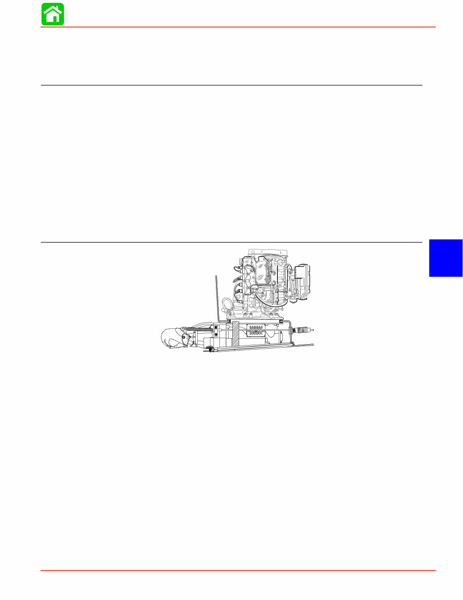
SPORT JET INSTALLATION Page 6A-2 90-858804 AUGUST 1998 General Information Notice to Installer Throughout this publication, “Warnings” and “Cautions” (accompanied by the International Hazard Symbol ! ) are used to alert the installer to special instructions concerning a particu- lar service or operation that may be hazardous if performed incorrectly or carelessly. –– Ob- serve Them Carefully! These “Safety Alerts,” alone, cannot eliminate the hazards that they signal. Strict com- pliance to these special instructions when performing the service, plus “common sense” op- eration, are major accident prevention measures. WARNING Hazards or unsafe practices which COULD result in severe personal injury or death. CAUTION Hazards or unsafe practices which could result in minor personal injury or product or property damage. IMPORTANT: Indicates information or instructions that are necessary for proper in- stallation and/or operation. This installation manual has been written and published by the service department of Mer- cury Marine to aid installers when installing the products described herein. It is assumed that these personnel are familiar with the installation procedures of these prod- ucts, or like or similar products manufactured and marketed by Mercury Marine. Also, that they have been trained in the recommended installation procedures of these products which includes the use of mechanics’ common hand tools and the special Mercury Marine or rec- ommended tools from other suppliers. We could not possibly know of and advise the marine trade of all conceivable procedures by which an installation might be performed and of the possible hazards and/or results of each method. We have not undertaken any such wide evaluation. Therefore, anyone who uses an installation procedure and/or tool, which is not recommended by the manufacturer, first must completely satisfy himself that neither his nor the product’s safety will be endan- gered by the installation procedure selected. All information, illustrations, and specifications contained in this manual are based on the latest product information available at time of publication. As required, revisions to this man- ual will be sent to all OEM boat companies. INSTALLATION PRODUCTS Loctite “271” 92-823089--1 Quicksilver Anti-Corrosion Grease 92-78376A6 Liquid Neoprene 92-25711--2 Dielectric Grease 92-823506--1 Perfect Seal 92-34227--1
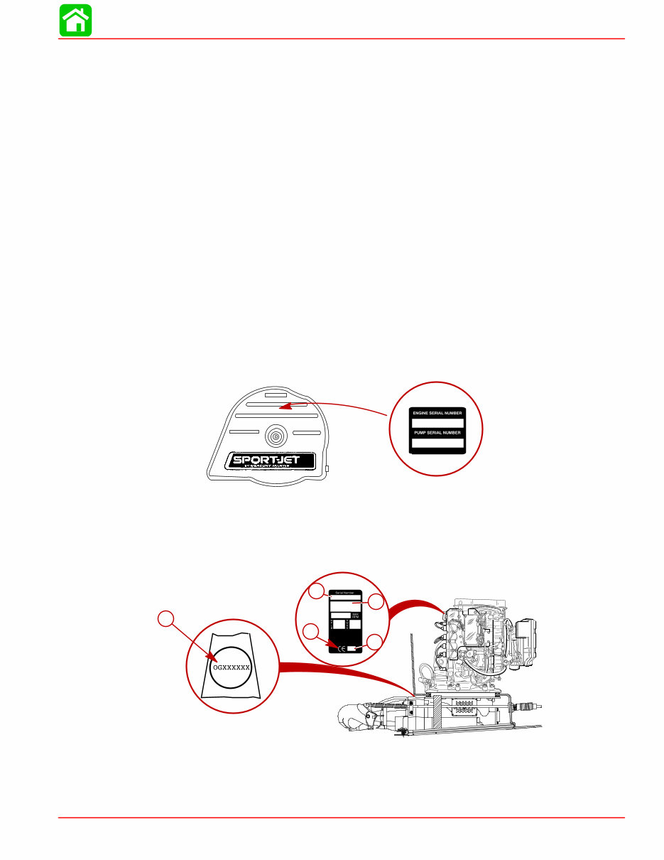
SPORT JET INSTALLATION 90-858804 AUGUST 1998 Page 6A-3 Torque Specifications NOTE: Tighten all fasteners, not listed, securely. Exhaust Bellows Clamps 50 lb. in. (5.6 N·m) Shift Cable Swivel Screws 50 lb. in. (5.6 N·m) Shift Cable Mounting Bracket Screws 50 lb. in. (5.6 N·m) 8 mm Fasteners(Powerhead to Pump) 20 lb. ft. (27 N·m) 10 mm Fasteners (Powerhead to Pump) 35 lb. ft. (47 N·m) Cooling Waterline Nut Snug with Wrench, Then Tighten One Addition Flat (60 degrees) Steering Cable Mounting Bracket Screws 200 lb. in. (23 N·m) Reverse Stop Screw 120 lb. in. (14 N·m) Forward Stop Screw 120 lb. in. (14 N·m) Ride Plate-to-Pump Screws 75 lb. in. (8.5 N·m) Drive Housing Cover to Drive Housing fasteners 35 lb. ft. (47 N·m) Serial Number Decal Location A serial number decal is located on the flywheel cover. OGXXXXXX IMPORTANT: The Pump Unit Serial Number sticker must be taken out of the envelope affixed to the pump unit and applied to the flywheel cover decal. The engine serial number and pump serial number are different and unique. The engine se- rial number is located aft of the flywheel cover. The pump unit serial number is stamped in a plug located above the shift cable hole on the port side of the pump housing. 19XX XX OGXXXXXX a b c d e a- Engine Serial Number b- Model Year c- Year Manufactured d- Certified Europe e- Pump Unit Serial Number
SPORT JET INSTALLATION Page 6A-4 90-858804 AUGUST 1998 Corrosion Protection This power package is equipped with anodes to help protect it from galvanic corrosion under moderate conditions. See the Operator’s Manual for location of anodes. Installation Requirements IMPORTANT: The Sport Jet is considered an INBOARD engine. The boat it is installed in must meet industry standards (ABYC, NMMA, etc.), federal standards and Coast Guard regulations for INBOARD engine installations Battery/Battery Cables IMPORTANT: Boating industry standards (ABYC, NMMA, etc.), federal standards and Coast Guard regulations must be adhered to when installing battery. Be sure battery cable installation meets the pull test requirements and that positive battery terminal is properly insulated in accordance with regulations. IMPORTANT: Engine electrical system is negative (–) ground. It is recommended (re- quired in some states) that battery be installed in an enclosed case. Refer to regula- tions for your area. 1. Select a battery that meets all of the following specifications: a. 12-volt marine type. b. 670 Marine Cranking Amps (MCA) or 520 Cold Cranking Amps (CCA). c. Reserve capacity rating of at least 100 minutes. 2. Select proper size positive (+) and negative (–) battery cables using chart. Battery should be located as close to engine as possible. IMPORTANT: Terminals must be soldered to cable ends to ensure good electrical contact. Use electrical grade (resin flux) solder only. Do not use acid flux solder, as it may cause corrosion and a subsequent failure. Cable Length Cable Gauge Up to 3-1/2 ft. (1.1 m) 4 (25 mm 2 ) 3-1/2 - 6 ft. (1.1-1.8 m) 2 (35 mm 2 ) 6 - 7-1/2 ft. (1.8-2.3 m) 1 (50 mm 2 ) 7-1/2 - 9-1/2 ft. (2.3-2.9 m) 0 (50 mm 2 ) 9-1/2 - 12 ft. (2.9-3.7 m) 00 (70 mm 2 ) 12 - 15 ft. (3.7-4.6 m) 000 (95 mm 2 ) 15 - 19 ft. (4.6-5.8 m) 0000 (120 mm 2 ) Boat Construction IMPORTANT: All applicable Coast Guard regulations for INBOARD engines must be complied with, when constructing engine compartment. Care must be exercised in the design and construction of the engine compartment. Seams must be located so that any rain water or splash, which may leak through the seams, is di- rected away from the engine and carburetor cover. Also, the passenger compartment drain- age system should not be routed directly to the engine compartment. Water that runs on or is splashed in the carburetor cover may enter the engine and cause serious dam- age to internal engine parts. IMPORTANT: Mercury Marine will not honor any warranty claim for engine damage as a result of water entry.
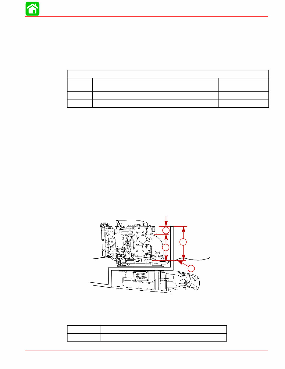
SPORT JET INSTALLATION 90-858804 AUGUST 1998 Page 6A-5 Engine Compartment Ventilation Engine compartment must be designed to provide a sufficient volume of air for engine breathing and also must vent off any fumes in engine compartment in accordance with industry standards (ABYC, NMMA, etc.), federal standards and Coast Guard regulations for inboard engines. Pressure differential (outside engine compartment versus inside engine compartment) should not exceed 2 in. (51 mm) of water (measured with a manometer) at maximum air flow rate. Engine Compartment Specifications Model Engine Air Requirements at Wide Open Throttle Physical Engine Volume* 95 HP 230 ft. 3 /min. (0.109m 3 /sec.) 0.60 ft. 3 (17 L) 120 HP 304 ft. 3 /min. (0.143 m 3 /sec.) 0.67 ft. 3 (19 L) * Physical engine volume is used in flotation calculations and is representative of the amount of flotation the engine provides. For serviceability, it is recommended that an additional 6 inches minimum (152 mm) (per side) of clearance be allowed between powerhead and engine compartment walls. Exhaust System IMPORTANT: It is the responsibility of the boat manufacturer, or installing dealer, to properly locate the engine. Improper installation may allow water to enter the exhaust manifold and combustion chambers and severely damage the engine. Damage caused by water in the engine will not be covered by Mercury Marine Limited Warranty, unless this damage is the result of defective part(s). The engine must be properly located to ensure that water will not enter the engine through the exhaust system. Determine the correct engine height by taking measurements (a) and (b), with boat at rest in the water and maximum load aboard. Subtract (b) from (a) to find (c). If (c) is less than specified in chart, boat construction must be altered to properly lower waterline relative to exhaust elbow. a b c d a- From Waterline to Top of Transom b- From Highest Point on Exhaust Elbow to Top of Transom c- (a) minus (b) = (c) d- Waterline at Rest (at Maximum Load) Model c = (a) minus (b) 95/120 HP (c) must be 7.5 in. (330 mm) or more.
SPORT JET INSTALLATION Page 6A-6 90-858804 AUGUST 1998 Fuel Delivery System WARNING Boating standards (NMMA, ABYC, etc.), federal standards and U. S. Coast Guard regulations for INBOARD engines must be adhered to when installing fuel delivery system. Failure to comply could result in severe personal injury or death. CAUTION Remove plastic plug from fuel inlet fitting. Attach fuel line to fuel fitting with U.S. Coast Guard approved hose clamp. Inspect for fuel leaks. 1. Fuel tank should be mounted below carburetor(s) level (if possible) or gravity feed may cause carburetor fuel inlet needle(s) to unseat, and flooding may result. 2. Fuel pickup should be at least 1 in. (25 mm) from the bottom of the fuel tank to prevent picking up impurities. 3. Fuel lines used must be Coast Guard approved (USCG type A1), fittings and lines must not be smaller than 5/16 in. (8 mm) I.D. 4. On installations requiring long lines or numerous fittings, larger size lines should be used. 5. Fuel line should be installed free of stress and firmly secured to prevent vibration and/or chafing. 6. Sharp bends in fuel line should be avoided. 7. A flexible fuel line must be used to connect fuel line to engine fuel pump to absorb deflec- tion when engine is running. 8. A primer bulb is not necessary with this application. If a primer bulb is used, it must be Coast Guard approved for inboard engine applications. 9. Mount the fuel primer pump in a suitable location in the boat. Follow the installation instructions which are provided with the fuel primer pump. a a- Fuel Primer Pump IMPORTANT: Fuel Primer Pump must be mounted within 12” of the powerhead per U.S. Coast Guard regulation.
SPORT JET INSTALLATION 90-858804 AUGUST 1998 Page 6A-7 Instrumentation CAUTION If a fused accessory panel is to be used, it is recommended that a separate circuit (properly fused) be used from the battery to the fuse panel with sufficient wire size to handle the intended current load. NOTE: The charging system on these engines is capable of producing 9 amps maximum charge at 3500 RPM (4.5 amps minimum at 1000 RPM). The electrical load of the boat should not exceed this capacity. If loads higher than the capacity of the charging system are anticipated, refer to “Quicksilver Accessory Guide” for a high output alternator. We recommend the use of Quicksilver Instrumentation and Wiring Harness(es). Refer to “Quicksilver Accessories Guide” for selection. If other than Quicksilver electrical accessories are to be used, it is good practice to use waterproof ignition components (ignition switch, lanyard stop switch, etc.). A typical jet boat of this nature will see water splashed on these components. Therefore, precautions must be taken to avoid ignition failure due to shorting out of ignition components. WARNING Sudden stopping of engine (shorting ignition components) while boat is underway will cause loss of steering control due to loss of thrust. This loss of steering control may cause property damage, personal injury or death. A warning horn must be incorporated in the wiring harness (see wiring diagram) to alert the user of an overheat or low oil condition. IMPORTANT: If a warning horn system is not installed by the boat manufacturer, Mer- cury Marine will not honor any warranty claims for engine damage as a result of over- heating or lack of engine oil. Route instrumentation wiring harness back to engine, making sure that harness does not rub or get pinched. If an extension harness is required, be sure to secure connection proper- ly. Fasten harness(es) to boat at least every 18 in. (460 mm), using appropriate fasteners.
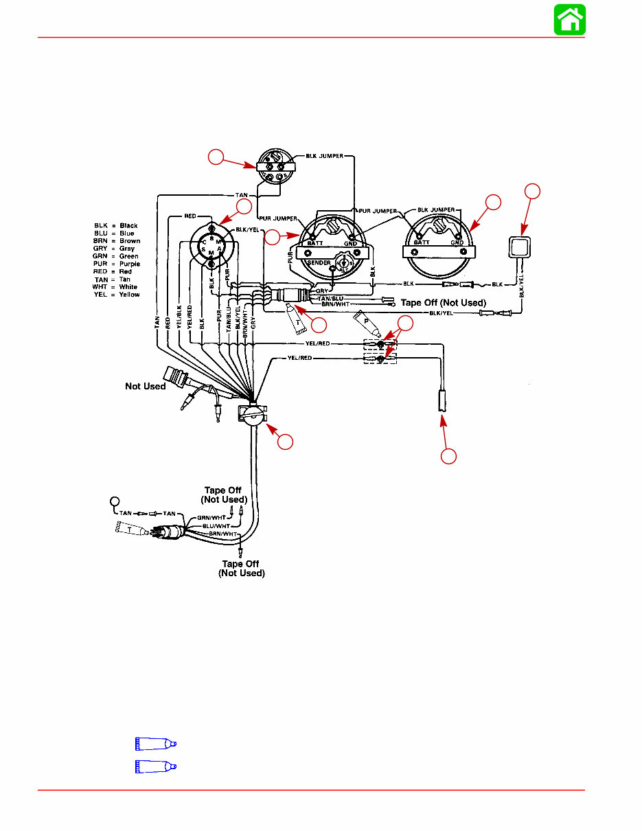
SPORT JET INSTALLATION Page 6A-8 90-858804 AUGUST 1998 Wiring Diagrams QUICKSILVER INSTRUMENTATION, TYPICAL INSTALLATION SHOWN Refer to gauge manufacturer’s instructions for specific connections. NOTE: When fastening bullet connectors use force to ensure a positive connection. NOTE: If gauge options are not used, tape back unused wiring harness leads. (Included With Gauge) Temperature Sender i a b c d e f g h i a- Temperature Gauge b- Key Switch c- Tachometer Gauge d- Emergency Stop Switch e- Tachometer Harness (P/N 84-86396A8) (Not Included with Key/Choke Harness Kit) f- Connect Wires Together with Screw and Hex Nut (2 places). Apply Quicksilver Liquid Neoprene to connections and slide rubber sleeve over each connection. g- To Neutral Start Safety Switch in Remote Control Box h- Speedometer Gauge i - Overheat/Low Oil Horn P Liquid Neoprene (92-25711--2) T Dielectric Grease (92-823506--1)
SPORT JET INSTALLATION 90-858804 AUGUST 1998 Page 6A-9 Impeller Selection IMPORTANT: Installed impeller must allow engine to run in its specified maximum wi- de-open-throttle RPM range. The jet drive comes equipped with a standard stainless steel impeller which allows the engine to operate in its specified operating range. If a different impeller is installed in place of the standard impeller, it is the responsibility of the installer to ensure engine RPM remains in specified range. Specified engine WOT RPM range is listed in “Operation and Maintenance Manual” attached to the engine. Remote Control and Cables To ensure proper shift and throttle operation, we recommend the use of the Sport Jet Re- mote Control (P/N 802755). This remote control has been qualified by Mercury Marine to be used with the Sport Jet and provides the following required features: • Start-in-gear protection • Neutral rpm limit at 2,000 rpm NOTE: This applies to dual lever remote controls as well as single lever remote controls • High strength mechanism to accommodate loads transmitted to the remote control • Shift cable travel of 3 inches "1/8 inch (76 mm "3 mm) • Ability to use 40 series shift cable If a remote control other than the Sport Jet Remote Control (P/N 802755) is used, the remote control must meet the above criteria as well as the design criteria outlined in the ABYC manual pertaining to Mini-Jet Boats (Standard P-23). SHIFT CABLE The shift cable to be used MUST MEET the following criteria: • 40-Series Cable • Allow for a minimum of 3 inches (76 mm) of travel. • A means of attaching and locking the cable to the wear ring. • Cable end at pump must allow for a clevis pin and cotter pin (all provided) to connect cable to the reverse gate. • Protected against water intrusion and/or corrosion as the cable end (at the pump) is sub- mersed in water with the boat at rest. A cable bellows is provided with the cable (P/N 64-858342A_). Follow installation proce- dures for proper sealing of cable. The shift cable end (at the pump) is submersed in water. It should be sealed against water intrusion, protected against corrosion and be able to withstand the shift loads imparted on it by the reverse gate. Follow shift cable adjustment procedure for proper adjustment. THROTTLE CABLE The throttle cable must have one end compatible with the control box. The other end must have Mercury style connectors. Follow throttle cable adjustment procedures for proper adjustment.
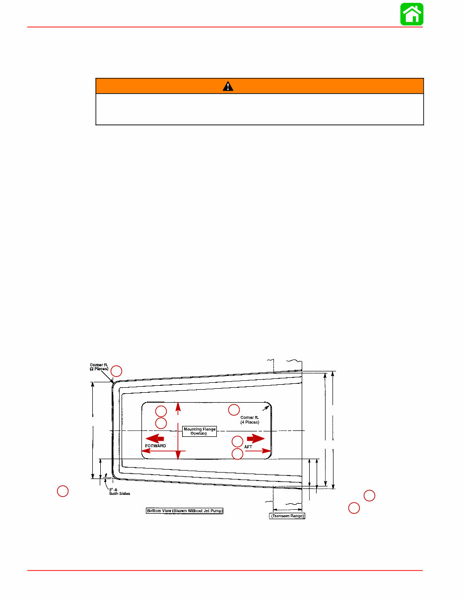
SPORT JET INSTALLATION Page 6A-10 90-858804 AUGUST 1998 Steering Helm and Cable STEERING HELM The steering helm must limit steering cable travel to 3.50 ± .10 inches (88.9 ± 2.5 mm). WARNING Failure to limit steering cable travel at the helm could pre-load the cable resulting in premature failure of a steering component causing loss of steering. This loss of steering could cause property damage, personal injury or death. STEERING CABLE The steering cable to be used MUST MEET the following criteria: • 60 Series Steering Cable • 60 Series bulkhead fitting at output end • Allow for a minimum of 3.75 inches (95.3 mm) of travel. • Cable end at pump must allow for a 5/16 in. threaded adaptor shouldered thru-bolt and lock nut to connect the cable to the steering arm. • A means of attaching and locking the cable to the steering cable bracket (provided). Sport Jet Hull Dimensions HULL OPENING CUT OUT The pump to powerhead opening in the hull is the most important factor to consider in a Sport Jet installation. There are three areas of concern: 1. Location (a) of the pump to powerhead hull cut out relative to the boat bottom for proper ride plate seal fit. 2. Dimensional control of the cutout - corner radii (b), straightness (c) and size (d) for prop- er grommet installation, and corner radii (e) for ride plate seal fit. 3. Flatness and thickness of the area around the hull cut out for proper grommet sealing (see drawing on next page). 1 1/16 +/– 1/16 3/4 +/– 1/16 7 1/16 +/– 1/16 16 1/4 +/– 1/16 14 11/16 +/– 1/16 14 5/16 +/– 1/16 2 9/16 +/– 1/16 12 1/8 +/– 1/16 3 13/16 +/– 1/16 3 5/8 +/– 1/16 Tunnel Dimensions (in inches) a e a a c d c d b a- Location b & e - Size and Straightness c & d - Size and Straightness
The Mercury Sport Jet 120 120XR Service Manual is a comprehensive resource for anyone involved in the repair and maintenance of the Mercury Sport Jet 120 and 120XR engines. This manual contains detailed information and step-by-step procedures for servicing, repairing, and maintaining the engines, making it an invaluable tool for professional mechanics and DIY enthusiasts alike.
Whether you are looking to troubleshoot a specific issue or perform routine maintenance, this manual provides the necessary guidance and technical specifications to ensure the job is done accurately and efficiently. With its in-depth explanations and illustrations, the manual equips users with the knowledge needed to tackle various tasks related to the Mercury Sport Jet 120 and 120XR engines.