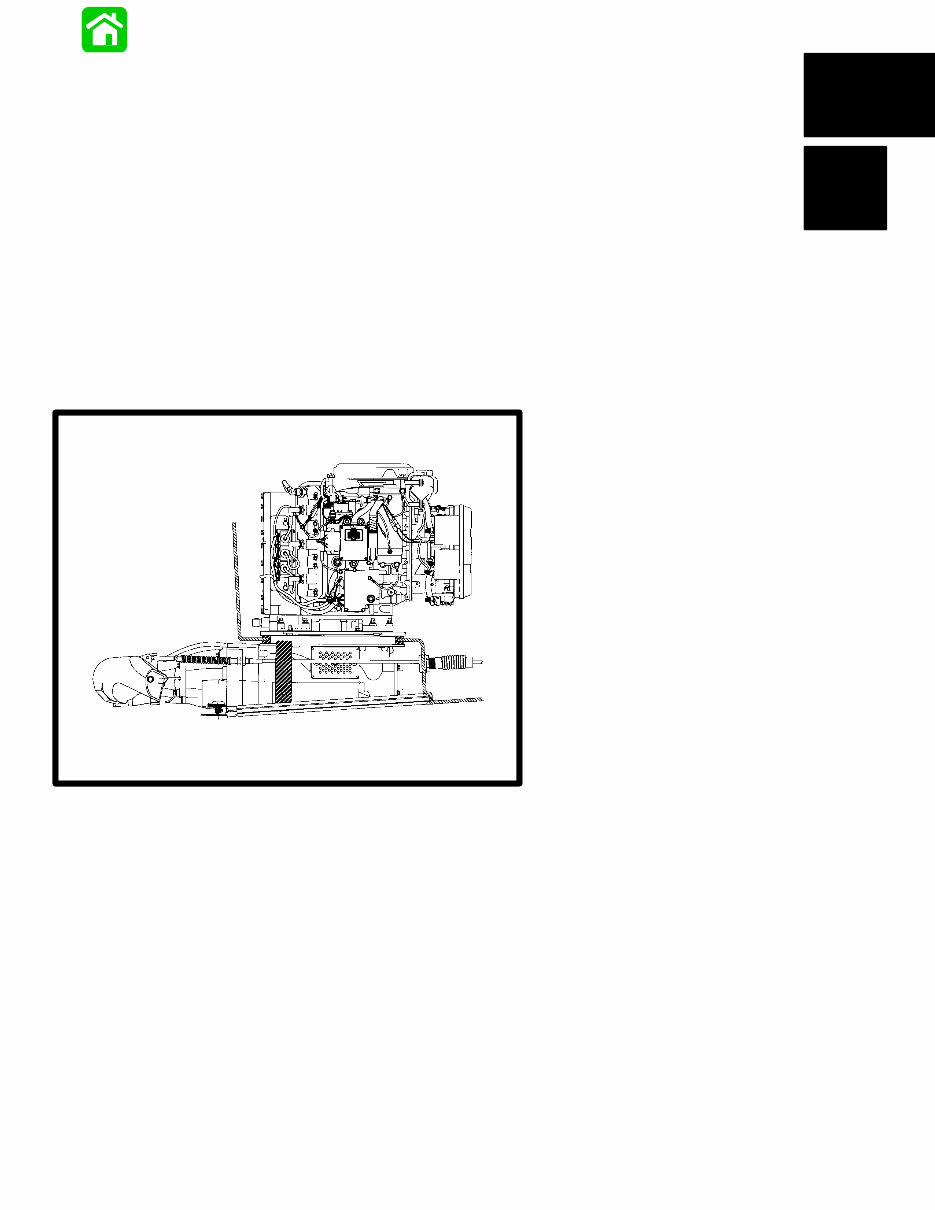
Printed in U.S.A. 90-852396R1 NOVEMBER 1997 1997, Mercury Marine MODELS 175XR 2 Sport Jet United States With Starting Serial Numbers Powerhead Pump Unit 0E203000 0E151580
IMPORTANT INFORMATION - 1C-1 90-852396 MAY 1996 Notice Throughout this publication, “Dangers”, “Warnings” and “Cautions” (accompanied by the International HAZARD Symbol ) are used to alert the mechanic to special instructions concerning a particular service or operation that may be hazardous if performed in- correctly or carelessly. OBSERVE THEM CARE- FULLY! These “Safety Alerts” alone cannot eliminate the haz- ards that they signal. Strict compliance to these spe- cial instructions when performing the service, plus “Common Sense” operation, are major accident pre- vention measures. DANGER DANGER - Immediate hazards which WILL result in severe personal injury or death. WARNING WARNING - Hazards or unsafe practices which COULD result in severe personal injury or death. CAUTION Hazards or unsafe practices which could result in minor personal injury or product or property damage. Notice to Users of This Manual This service manual has been written and published by the Service Department of Mercury Marine to aid our dealers’ mechanics and company service per- sonnel when servicing the products described here- in. It is assumed that these personnel are familiar with the servicing procedures of these products, or like or similar products manufactured and marketed by Mercury Marine, that they have been trained in the recommended servicing procedures of these prod- ucts which includes the use of mechanics’ common hand tools and the special Mercury Marine or recom- mended tools from other suppliers. We could not possibly know of and advise the service trade of all conceivable procedures by which a ser- vice might be performed and of the possible hazards and/or results of each method. We have not under- taken any such wide evaluation. Therefore, anyone who uses a service procedure and/or tool, which is not recommended by the manufacturer, first must completely satisfy himself that neither his nor the products safety will be endangered by the service procedure selected. All information, illustrations and specifications con- tained in this manual are based on the latest product information available at the time of publication. As re- quired, revisions to this manual will be sent to all deal- ers contracted by us to sell and/or service these prod- ucts. It should be kept in mind, while working on the prod- uct, that the electrical system and ignition system are capable of violent and damaging short circuits or se- vere electrical shocks. When performing any work where electrical terminals could possibly be grounded or touched by the mechanic, the battery cables should be disconnected at the battery. Any time the intake or exhaust openings are exposed during service they should be covered to protect against accidental entrance of foreign material which could enter the cylinders and cause extensive inter- nal damage when the engine is started. It is important to note, during any maintenance proce- dure replacement fasteners must have the same measurements and strength as those removed. Numbers on the heads of the metric bolts and on the surfaces of metric nuts indicate their strength. Ameri- can bolts use radial lines for this purpose, while most American nuts do not have strength markings. Mis- matched or incorrect fasteners can result in damage or malfunction, or possibly personal injury. There- fore, fasteners removed should be saved for reuse in the same locations whenever possible. Where the fasteners are not satisfactory for re-use, care should be taken to select a replacement that matches the original.
1C-2 - IMPORTANT INFORMATION 90-852396 MAY 1996 Cleanliness and Care of Sport Jet A marine power product is a combination of many machined, honed, polished and lapped surfaces with tolerances that are measured in the ten thousands of an inch/mm. When any product component is serv- iced, care and cleanliness are important. Throughout this manual, it should be understood that proper cleaning, and protection of machined surfaces and friction areas is a part of the repair procedure. This is considered standard shop practice even if not specif- ically stated. Whenever components are removed for service, they should be retained in order. At the time of instal- lation, they should be installed in the same locations and with the same mating surfaces as when re- moved. Before raising or removing an engine from a boat, the following precautions should be adhered to: 1. Check that flywheel is secured to end of crank- shaft with a locknut and lifting eye is threaded into flywheel a minimum of 5 turns. 2. Connect a hoist of suitable strength to the lifting eye. In addition, personnel should not work on or under an engine which is suspended. Engines should be at- tached to work stands, or lowered to ground as soon as possible. We reserve the right to make changes to this manual without prior notification. Refer to dealer service bulletins for other pertinent in- formation concerning the products described in this manual. Page Numbering Two number groups appear at the bottom of each page. The example below is self-explanatory. EXAMPLE: 90-826148 R1 JANUARY 1993 POWERHEAD - 5A-7 Revision No. 1 Month of Printing Year of Printing Section Description Section Number Part of Section Letter Page Number
Important Information Electrical Fuel System Powerhead Pump Unit 1 2 3 4 5 IMPORTANT INFORMATION - 1C-3 90-852396 MAY 1996 Service Manual Outline Section 1 - Important Information A - Specifications B - Maintenance C - General Information D - Sport Jet Installation Section 2 - Electrical A - Ignition B - Charging & Starting System C - Timing, Synchronizing & Adjusting Section 3 - Fuel System A - Fuel Pump & Fuel Primer B - Carburetor C - Oil Injection D - Electronic Enrichment & Turn Key Start Electronic Control Module Section 4 - Powerhead Section 5 - Pump Unit
1C-4 - IMPORTANT INFORMATION 90-852396 MAY 1996 NOTES:
IMPORTANT INFORMATION - 1A-1 90-852396 MAY 1996 Master Specifications Model 175 HORSEPOWER (KW) 175(130.5) SPORT JET WEIGHT Powerhead Pump Unit 205 lb. (93 kg) 100 lb. (45 kg) CYLINDER BLOCK Type Displacement V-6 Cylinder, Two Cycle, Loop Charged 153.0 cu. in. (2507cc) STROKE Length (All Models) 2.650 in. (67.31mm) CYLINDER BORE Diameter (Std) Taper/Out of Round/Maximum Wear Bore Type 3.501 in. (88.925mm) 0.003 in. (0.076mm) Cast Iron PISTON Piston Type Standard 0.015 in. (0.381 mm) Oversize Aluminum 3.494 in. ± 0.001 in. (88.748mm ± 0.025mm) 3.509 in. ± 0.001 in. (89.129mm ± 0.025mm) REEDS Reed Type Reed Stand 0pen (Max.) Reed Stop (Max.) Steel 0.020 in. (0.50mm) Not Adjustable FUEL SYSTEM Fuel Recommended Gasoline Recommended Oil Gasoline/Oil Ratio Fuel Pressure – @ Idle – @ WOT Gasoline w/Oil Injection Unleaded 87 Octane Minimum Quicksilver TC-W3 or TC-WII 2 Cycle Outboard Oil Only 50:1 (25:1 Break-In) 2 PSI 8 PSI STARTING SYSTEM Electric Start – All Models Starter Draw (Under Load) Starter Load (No Load) Battery Rating 175 Amperes 40 Amperes 670 Marine Carnking Amps (MCA) or 520 Cold Cranking Amps (CCA) IGNITION SYSTEM Type Spark Plug Type Spark Plug Gap Capacitor Discharge NGK BU8H Surface Gap CHARGING SYSTEM Alternator Output (Regulated) 12 Amperes @ 3000 RPM
90-852396 MAY 1996 1A-2 - IMPORTANT INFORMATION Master Specifications (Continued) 175XR 2 Sport Jet (Continued) Carburetor Idle RPM Wide Open Throttle (WOT) RPM Idle Mixture Screw Adjustment (Preset - Turns Out) – All Carbs Float Setting Main Jet –Top Carb –Middle Carb –Bottom Carb Idle Air Jet –Top Carb –Middle Carb –Bottom Carb Vent Jet –Top Carb –Middle Carb –Bottom Carb 1000 - 1100 RPM 5000 - 5500 1-1/2 turns out from a lightly seated position Set parallel to body flange .076 .076 .076 .050 .050 Port .054 Starbboard .050 .080 .080 .080 Timing Maximum Timing BTDC @ Cranking Speed @ 5000 RPM Idle Timing ATDC Firing Order 22° BTDC 20° BTDC 0° 2° @ 1000 - 1100 RPM 1-2-3-4-5-6
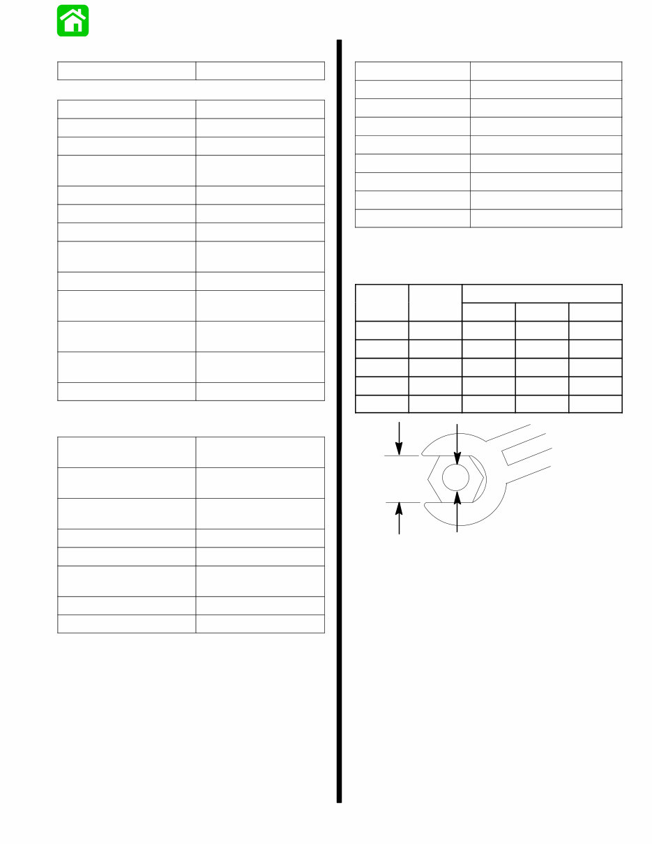
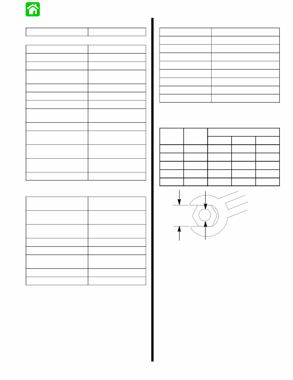
IMPORTANT INFORMATION - 1A-3 90-852396 MAY 1996 Torque Chart Special Items Torque PUMP UNIT Impeller Nut 150 lb. ft. (203 N·m) Impeller Gear Nut 90 lb. ft. (122 N·m) Pinion Shaft Assembly 180 lb. in. (20 N·m) Drive Housing Cover Nuts 35 lb. ft. (47.5 N·m) Stator Bolts 35 lb. ft. (47.5 N·m) Nozzle to Stator Bolts 35 lb. ft. (47.5 N·m) Rudder Pivot Bolt 50 lb. ft. (68 N·m) Reverse Gate Pivot Bolt 50 lb. ft. (68 N·m) Steering Lever Screw 180 lb. in. (20.2 N·m) Reverse Gate Stop Screw 120 lb. in. (13.6 N·m) Inlet Screen Screw (6 mm) 75 lb. in. (8.5 N·m) Inlet Screen Screw (8 mm) 200 lb. in. (23 N·m) Ride Plate Screw 75 lb. in. (8.5 N·m) POWERHEAD Adaptor Plate to Powerhead 35 lb. ft. (47.5 N·m) Powerhead to Drive Housing Nuts 35 lb. ft. (47.5 N·m) Cylinder Head 225 lb. in. (25.4 N·m) Then Turn Additional 90_ Flywheel Nut 125 lb. ft. (169.5 N·m) Main Bearing Bolts 270 lb. in. (30.4 N·m) Connecting Rod Screws 120 lb. in. (13.6 N·m) Then Turn Additional 90_ Transfer Port Cover 80 lb. in. (9.03 N·m) Exhaust Manifold 180 lb. in. (20 N·m) Standard Hardware Screw or Nut Size Torque 6 - 32 9 lb. in. (1.0 N·m) 8 - 32 20 lb. in. (2.3 N·m) 10 - 24 30 lb. in. (3.4 N·m) 10 - 32 35 lb. in. (3.9 N·m) 12 - 24 45 lb. in. (5.0 N·m) 1/4 - 20 70 lb. in. (7.8 N·m) 5/16 - 18 160 lb. in. (18.1 N·m) 3/8 - 16 270 lb. in. (30.4 N·m) Metric Hardware A B Torque Specification A B lb. in. lb. ft. N·m 8 mm M5 36 3 4 10 mm M6 70 6 8 12 mm M8 156 13 18 14 mm M10 312 26 36 17 mm M12 372 31 42 A B
Complete Service manual for the Mercury 175XR2 Sport Jet Drive is your ultimate resource for repair and service information. This manual is designed for both do-it-yourself enthusiasts and experienced mechanics. It offers cost-effective solutions to maintain your motor's optimal functionality. With step-by-step instructions derived from the complete disassembly of the machine, accompanied by numerous photos and illustrations, this manual provides comprehensive guidance through each service and repair procedure.
Whether stored on your hard drive, burned to a CD-ROM, or printed, this manual offers versatile accessibility. Detailed substeps further elaborate on repair procedures, while notes, cautions, and warnings throughout each chapter highlight critical information. Numbered instructions systematically lead you through every repair procedure, complemented by bold figure numbers for quick illustration matching. Detailed illustrations, drawings, and photos, along with enlarged insets, facilitate thorough part examination. The numbered table of contents ensures swift access to the required information.
This manual also simplifies the diagnosis and repair of electrical system issues, combining troubleshooting and electrical service procedures with detailed wiring diagrams for user convenience.