115/135/150/175 OptiMax Direct Fuel Injection Starting Model Year 2000 Starting Serial Number OG960500 Starting Model Year 2000 Starting S/N OG960500 115/135/150/175 OptiMax
90-859494R1 JUNE 2000 Page i Notice Throughout this publication, “Dangers”, “Warnings” and “Cautions” (accompanied by the In- ternational HAZARD Symbol ) are used to alert the mechanic to special instructions con- cerning a particular service or operation that may be hazardous if performed incorrectly or carelessly. OBSERVE THEM CAREFULLY! These “Safety Alerts” alone cannot eliminate the hazards that they signal. Strict compliance to these special instructions when performing the service, plus “Common Sense” operation, are major accident prevention measures. DANGER DANGER - Immediate hazards which WILL result in severe personal injury or death. WARNING WARNING - Hazards or unsafe practices which COULD result in severe personal in- jury or death. CAUTION Hazards or unsafe practices which could result in minor personal injury or product or property damage. Notice to Users of This Manual This service manual has been written and published by the Service Department of Mercury Marine to aid our dealers’ mechanics and company service personnel when servicing the products described herein. It is assumed that these personnel are familiar with the servicing procedures of these prod- ucts, or like or similar products manufactured and marketed by Mercury Marine, that they have been trained in the recommended servicing procedures of these products which in- cludes the use of mechanics’ common hand tools and the special Mercury Marine or recom- mended tools from other suppliers. We could not possibly know of and advise the service trade of all conceivable procedures by which a service might be performed and of the possible hazards and/or results of each method. We have not undertaken any such wide evaluation. Therefore, anyone who uses a service procedure and/or tool, which is not recommended by the manufacturer, first must completely satisfy himself that neither his nor the products safety will be endangered by the service procedure selected. All information, illustrations and specifications contained in this manual are based on the latest product information available at the time of publication. As required, revisions to this manual will be sent to all dealers contracted by us to sell and/or service these products. It should be kept in mind, while working on the product, that the electrical system and ignition system are capable of violent and damaging short circuits or severe electrical shocks. When performing any work where electrical terminals could possibly be grounded or touched by the mechanic, the battery cables should be disconnected at the battery. Any time the intake or exhaust openings are exposed during service they should be covered to protect against accidental entrance of foreign material which could enter the cylinders and cause extensive internal damage when the engine is started.
Page ii 90-859494R1 JUNE 2000 It is important to note, during any maintenance procedure replacement fasteners must have the same measurements and strength as those removed. Numbers on the heads of the met- ric bolts and on the surfaces of metric nuts indicate their strength. American bolts use radial lines for this purpose, while most American nuts do not have strength markings. Mis- matched or incorrect fasteners can result in damage or malfunction, or possibly personal injury. Therefore, fasteners removed should be saved for reuse in the same locations when- ever possible. Where the fasteners are not satisfactory for re-use, care should be taken to select a replacement that matches the original. Cleanliness and Care of Outboard Motor A marine power product is a combination of many machined, honed, polished and lapped surfaces with tolerances that are measured in the ten thousands of an inch/mm. When any product component is serviced, care and cleanliness are important. Throughout this manu- al, it should be understood that proper cleaning, and protection of machined surfaces and friction areas is a part of the repair procedure. This is considered standard shop practice even if not specifically stated. Whenever components are removed for service, they should be retained in order. At the time of installation, they should be installed in the same locations and with the same mating surfaces as when removed. Personnel should not work on or under an outboard which is suspended. Outboards should be attached to work stands, or lowered to ground as soon as possible. We reserve the right to make changes to this manual without prior notification. Refer to dealer service bulletins for other pertinent information concerning the products de- scribed in this manual. Page Numbering Two number groups appear at the bottom of each page. The example below is self-explana- tory. EXAMPLE: 90-859494 R1 MAY 2000 LOWER UNIT - 6A-7 Revision No. 1 Month of Printing Year of Printing Section Description Section Number Part of Section Letter Page Number
1 2 3 4 5 6 7 General Information & Specifications Ignition System Fuel System Powerhead Mid-Section Gear Housing Attachment/Control Linkage 8 Color Diagrams 90-859494R1 JUNE 2000 Page iii Service Manual Outline Section 1 - General Information & Specifications A - Specifications B - Maintenance C - General Information D - Outboard Installation Section 2 - Electrical A - Ignition B - Charging & Starting System C - Timing, Synchronizing & Adjusting D - Wiring Diagrams Section 3 - Fuel System A - Fuel Pump B - Direct Fuel Injection C - Oil Injection D - Emissions Section 4 - Powerhead A - Powerhead B - Cooling Section 5 - Mid-Section A - Clamp/Swivel Brackets & Drive Shaft Housing B - Power Trim – Design I (Showa) C - Power Trim – Design II (Oildyne) Section 6 - Gear Housing A - Right Hand (Standard) Rotation Non-Ratcheting B - Left Hand (Counter) Rotattion Non-Ratcheting Section 7 - Attachments/Control Linkage Section 8 - Color Diagrams
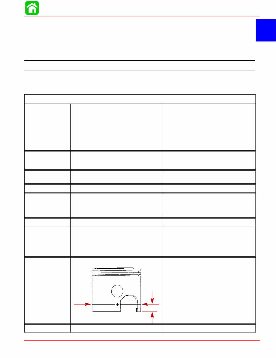
1 A SPECIFICATIONS 90-855347R1 JANUARY 1999 Page 1A-1 IMPORTANT INFORMATION Section 1A - Specifications Table of Contents Master Specifications 1A-1 . . . . . . . . . . . . . . . . . . . . . . . . . Master Specifications Model 135/150 DFI HORSEPOWER (KW) Model 135 Model 150 Full Throttle RPM (135/150) Idle RPM (In Gear) (135/150) RPM Limiter 1998 Model 135/150 1999 Model 135 1999 Model 150 135 (100.7 kw) 150 (111.8 kw) 5000 - 5600 550 ± 25 5750 5750 5950 OUTBOARD WEIGHT Model 135/150 – 20 in. (50.8cm) Shaft – 25 in. (63.5cm) Shaft 440.0 lbs. (200.0 kg) 452.0 lbs. (206.0 kg) CYLINDER BLOCK Type Displacement V-6 Cylinder, Two Cycle, Direct Injected 153 cu. in. (2508 cc) 60° Vee STROKE Length (All Models) 2.65 in. (67.3 mm) CYLINDER BORE Diameter (Std) Diameter 0.015 in. Oversize Taper/Out of Round/Wear Maximum Bore Type 3.501 in. (88.925 mm) 3.516 in. (89.306 mm) 0.003 in. (0.076 mm) Cast Iron CRANKSHAFT Maximum Runout 0.006 in. (0.152 mm) PISTON Piston Type Diameter Standard Diameter 0.015 in. Oversize Aluminum 3.4925 in. ± .0005 in. (88.7095 mm ± 0.0127 mm) 3.5075 in. ± 0.0005 in. (89.0905 mm ± 0.0127 mm) PISTON DIAMETER Dimension “A” at Right Angle (90°) to Piston Pin .700 17.78mm 3.4925 in. ± .0005 in. (88.7095 mm ± .0127 mm) Using a micrometer, measure dimension “A” at location shown. Dimension “A” should be 3.4925 in. ± .0005 for a STAN- DARD size piston (new) Dimension “A” will be 0.001 – 0.0015 less if coating is worn off piston (used) REEDS Reed Stand 0pen (Max.) 0.020 in. (0.50 mm)
SPECIFICATIONS Page 1A-2 90-855347R1 JANUARY 1999 Model 135/150 DFI MID SECTION Power Trim (Total Tilt Range) Power Trim (Tilt Range) Steering Pivot Range Tilt Pin Adjustment Positions Allowable Transom Thickness 73° 19° 60° 4 2-3/8 in. (6.03 cm) GEAR HOUSING Gear Ratio Standard Ratio – 135 Standard Ratio – 150 Optional High Altitude Ratio – 135 – 150 Gearcase Capacity Pinion Height Forward Gear Backlash – 1.87:1 – 2.00:1 – 2.30:1 Reverse Gear Backlash – Standard/Counter Rotation Water Pressure @ RPM 2.00:1 12/24 Teeth 1.87:1 15/28 Teeth 2.30:1 13/30 Teeth 2.00:1 12/24 Teeth 22.5 fl. oz. (665.4 ml) 0.025 in. (0.635 mm) . 0.017 in. – 0.028 in. (0.431 mm – 0.711 mm) 0.015 in. – 0.022 in. (0.381 mm – 0.558 mm) 0.018 in. – 0.023 in. (0.460 mm – 0.584 mm) 0.030 in. to 0.050 in. (0.076 mm to 0.127 mm) 12 PSI Minimum @ 5500 RPM DIRECT INJECTION Injectors – Quantity – Injectors are Crank Angle Driven by ECM – #2 Cylinder – #4 Cylinder – #6 Cylinder – #1 Cylinder – #3 Cylinder – #5 Cylinder Fuel Line Pressure @ Injectors Air Pressure High Pressure Electric Fuel Pump Amperage Draw Low Pressure Electric Fuel Pump Amperage Draw Low Pressure Electric Fuel Pump Output Fuel Injector Ohm Resistance Direct Injector Ohm Resistance Fuel/Air Differential 6 WHT/RED + RED/WHT Leads WHT/YEL + YEL/WHT Leads WHT/PPL + PPL/WHT Leads WHT/BRN + BRN/WHT Leads WHT/ORG + ORG/WHT Leads WHT/DRK BLU + DRK BLU/WHT Leads 89 ± 2 psi (613.5 ± 13.8 kPa) 79 ± 2 psi (544.0 ± 13.8 kPa) 5 – 9 Amperes 1 – 2 Amperes 6 – 9 psi (41.37 – 62.04 kPa) 1.8 ± 0.1 Ω 1.3 ± 0.3 Ω 10 psi (68.5 kPa)
SPECIFICATIONS 90-855347R1 JANUARY 1999 Page 1A-3 Master Specifications Model 135/150 DFI FUEL SYSTEM Fuel Recommended Gasoline Recommended Oil Gasoline/Oil Ratio – @ Idle – @ WOT Fuel Pressure Crankcase Pump – @ Idle – @ WOT Gasoline w/Oil Injection Unleaded 87 Octane Minimum Quicksilver TC-W3 Premium Plus 2 Cycle Outboard Oil 300 – 400:1 60:1 2 psi (13.8 kPa) 8 psi (55.2 kPa) STARTING SYSTEM Electric Start – All Models Starter Draw (Under Load) Starter Draw (No Load) Minimum Brush Length Battery Rating 165 Amperes 30 Amperes 0.25 in. (65.4 mm) 1000 (Minimum) Marine Cranking Amps (MCA) 750 (Minimum) Cold Cranking Amps (CCA) IGNITION SYSTEM Type Spark Plug Type Spark Plug Gap Maximum Timing Idle Timing Throttle Position Sensor 1 (Inner TPS) @ Idle @ W.O.T Throttle Position Sensor 2 (Outer TPS) @ Idle @ W.O.T Crank Position Sensor Air Gap Digital Inductive NGK PZFR5F-11 NGK ZFR5F-11 or Champion RC12MC4 0.040 in. (1.0 mm) Not Adjustable; Controlled by ECM Not Adjustable; Controlled by ECM 3.70 – 4.90 VDC 0.30 – 1.80 VDC 0.10 – 1.50 VDC 3.20 – 4.90 VDC 0.025 in. – 0.040 in. (0.635 mm – 1.01 mm) CHARGING SYSTEM Alternator Output (Regulated) Brush Length Voltage Output Regulator Current Draw 32 - 38 Amperes @ 2000 RPM @ Battery* 52 - 60 Amperes @ 2000 RPM @ Alternator Std Exposed Length: 0.413 in. (10.5 mm) Min. Exposed Length: 0.059 in. (1.5 mm) 13.5 to 15.1 Volts 0.15 mA (Ign. Switch Off) 30.0 mA (Ign. Switch On) *Amperage listed is when battery is in a discharged state. If battery is fully charged, amperage readings will be less.
Upon purchasing this manual, you will receive a .PDF file containing an email address for further assistance. After contacting the provided email, you will receive a reply with a link to access the manual for your Mercury 115 HP OptiMax Outboard.
This comprehensive manual covers every aspect of your machine, providing detailed guidance on every nut and bolt. With its extensive content spanning hundreds of pages, it equips you to address various issues, from routine maintenance like oil changes to more complex tasks such as transmission swaps. The manual includes numerous illustrations to assist you and features easy-to-understand text throughout.
Utilize the search function to navigate the manual efficiently and print the necessary pages as needed. This Factory Service Repair Manual serves as a thorough guide, walking you through the essential maintenance and repair procedures in a step-by-step manner, imparting the expertise typically possessed by factory-trained technicians.
By leveraging the insights within this service repair manual, both professional mechanics and DIY enthusiasts can confidently make informed decisions regarding the maintenance and repair of their machine.
Rest assured, in addition to providing a high-quality service manual, we are committed to delivering exceptional customer service, ensuring your satisfaction with your purchase.
Reviews
Q&A
Recently Viewed
5,521,897Happy Clients
2,594,462eManuals
1,120,453Trusted Sellers
15Years in Business
Price:
Actual Price:
Mercury 115HP OptiMax DFI Outboards OEM Service & Repair Manual