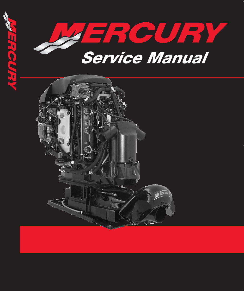
250 OptiMax Jet Drive Starting Model Year 2002 Starting Serial Number 0E407100 Starting Model Year 2002 90-888438 JUNE 2002 250 OptiMax Jet Drive
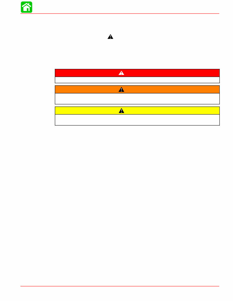
Page i 90-888438 JUNE 2002 Notice Throughout this publication, “Dangers”, “Warnings” and “Cautions” (accompanied by the In- ternational HAZARD Symbol ) are used to alert the mechanic to special instructions con- cerning a particular service or operation that may be hazardous if performed incorrectly or carelessly. OBSERVE THEM CAREFULLY! These “Safety Alerts” alone cannot eliminate the hazards that they signal. Strict compliance to these special instructions when performing the service, plus “Common Sense” operation, are major accident prevention measures. DANGER DANGER - Immediate hazards which WILL result in severe personal injury or death. WARNING WARNING - Hazards or unsafe practices which COULD result in severe personal in- jury or death. CAUTION Hazards or unsafe practices which could result in minor personal injury or product or property damage. Notice to Users of This Manual This service manual has been written and published by the Service Department of Mercury Marine to aid our dealers’ mechanics and company service personnel when servicing the products described herein. It is assumed that these personnel are familiar with the servicing procedures of these prod- ucts, or like or similar products manufactured and marketed by Mercury Marine, that they have been trained in the recommended servicing procedures of these products which in- cludes the use of mechanics’ common hand tools and the special Mercury Marine or recom- mended tools from other suppliers. We could not possibly know of and advise the service trade of all conceivable procedures by which a service might be performed and of the possible hazards and/or results of each method. We have not undertaken any such wide evaluation. Therefore, anyone who uses a service procedure and/or tool, which is not recommended by the manufacturer, first must completely satisfy himself that neither his nor the products safety will be endangered by the service procedure selected. All information, illustrations and specifications contained in this manual are based on the latest product information available at the time of publication. As required, revisions to this manual will be sent to all dealers contracted by us to sell and/or service these products. It should be kept in mind, while working on the product, that the electrical system and ignition system are capable of violent and damaging short circuits or severe electrical shocks. When performing any work where electrical terminals could possibly be grounded or touched by the mechanic, the battery cables should be disconnected at the battery. Any time the intake or exhaust openings are exposed during service they should be covered to protect against accidental entrance of foreign material which could enter the cylinders and cause extensive internal damage when the engine is started.
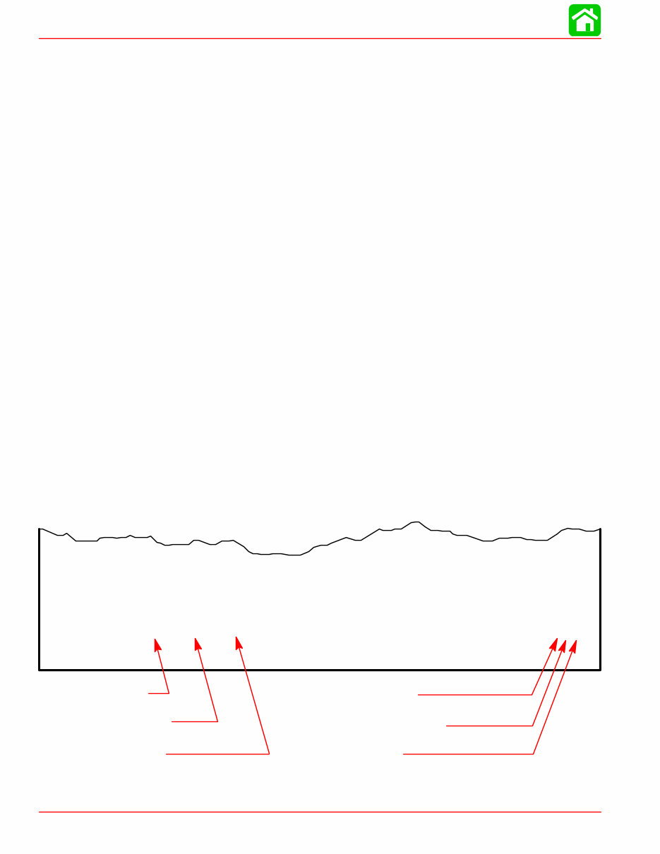
Page ii 90-888438 JUNE 2002 It is important to note, during any maintenance procedure replacement fasteners must have the same measurements and strength as those removed. Numbers on the heads of the met- ric bolts and on the surfaces of metric nuts indicate their strength. American bolts use radial lines for this purpose, while most American nuts do not have strength markings. Mis- matched or incorrect fasteners can result in damage or malfunction, or possibly personal injury. Therefore, fasteners removed should be saved for reuse in the same locations when- ever possible. Where the fasteners are not satisfactory for re-use, care should be taken to select a replacement that matches the original. Cleanliness and Care of Mercury Jet Unit A marine power product is a combination of many machined, honed, polished and lapped surfaces with tolerances that are measured in the ten thousands of an inch/mm. When any product component is serviced, care and cleanliness are important. Throughout this manu- al, it should be understood that proper cleaning, and protection of machined surfaces and friction areas is a part of the repair procedure. This is considered standard shop practice even if not specifically stated. Whenever components are removed for service, they should be retained in order. At the time of installation, they should be installed in the same locations and with the same mating surfaces as when removed. Personnel should not work on or under a powerhead which is suspended. Powerheads should be attached to work stands, or lowered to ground as soon as possible. We reserve the right to make changes to this manual without prior notification. Refer to dealer service bulletins for other pertinent information concerning the products de- scribed in this manual. Page Numbering Two number groups appear at the bottom of each page. The example below is self-explana- tory. EXAMPLE: 90-888438 JUNE 2002 Page 5A-7 Revision No. 1 Month of Printing Year of Printing Section Number Part of Section Letter Page Number
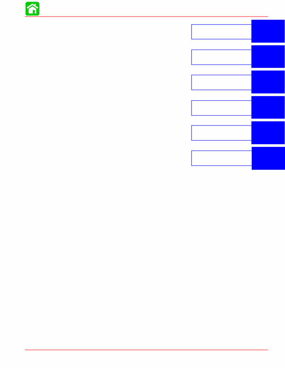
1 2 3 4 5 Important Information Electrical Fuel System Powerhead Pump Unit 6 Color Diagrams Page iii 90-888438 JUNE 2002 Service Manual Outline Section 1 - Important Information A - Specifications B - Maintenance C - General Information D - Jet Installation Section 2 - Electrical A - Ignition B - Charging & Starting System C - Timing, Synchronizing & Adjusting Section 3 - Fuel System A - Fuel Pump B - Direct Fuel Injection C - Oil Injection D - Emissions Section 4 - Powerhead A - Powerhead B - Cooling Section 5 - Pump Unit Section 6 - Color Diagrams
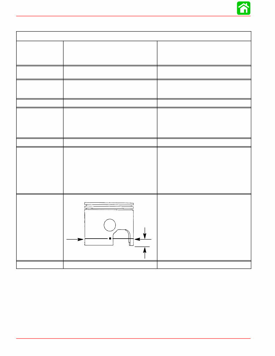
SPECIFICATIONS Page 1A-2 90-888438 JUNE 2002 Master Specifications Model 250 Optimax Jet HORSEPOWER (KW) Model 250 Full Throttle RPM Idle RPM (In Gear) RPM Limiter 250 (186.4) 5375±250 900 - 1100 5850 JET DRIVE WEIGHT Powerhead Pump Unit 312 (141.5 kg) 122 (55.3 kg) CYLINDER BLOCK Type Displacement Thermostat V-6 Cylinder, Two Cycle 185.9 cu. in. (3047 cc) 60° Vee None STROKE Length (All Models) 3.00 in. (76.2 mm) CYLINDER BORE Diameter (Std) Diameter 0.015 in. Oversize Diameter 0.030 in. Oversize Taper/Out of Round/Wear Maximum Bore Type 3.6265 in. (92.1131 mm) 3.6415 in. (92.4941 mm) 3.6565 in. (92.875 mm) 0.003 in. (0.076 mm) Cast Iron CRANKSHAFT Maximum Runout 0.002 in. (0.0508 mm) PISTON Piston Type Diameter Standard Diameter 0.015 in. Oversize Diameter 0.030 in. Oversize Aluminum 3.6210 in. ± .0005 in. (91.9734 mm ± 0.0127 mm) 3.6360 in. ± 0.0005 in. (89.0905 mm ± 0.0127 mm) 3.6510 in. ± 0.0005 in. (92.7354 mm ± 0.0127 mm) PISTON DIAMETER Dimension “A” at Right Angle (90°) to Piston Pin 1 in. (25.4 mm) 3.6210 in. ± .0005 in. (91.9734 mm ± .0127 mm) Using a micrometer, measure dimension “A” at location shown. Dimension “A” should be 3.6205 in. ± .0005 for a STAN- DARD size piston (new). Dimension “A” will be 0.001 – 0.0015 less if coating is worn off piston (used). REEDS Reed Stand 0pen (Max.) 0.020 in. (0.50 mm)
SPECIFICATIONS Page 1A-4 90-888438 JUNE 2002 Model 250 Optimax Jet Compressor STARTING SYSTEM Electric Start – All Models Solenoid Driven Bendix Starter Draw (Under Load) Starter Draw (No Load) Minimum Brush Length Battery Rating 170 Amperes 60 Amperes 0.25 in. (6.35 mm) 1000 (Minimum) Marine Cranking Amps 750 (Minimum) Cold Cranking Amps 105 (Minimum) Ampere Hours IGNITION SYSTEM Type Firing Order Spark Plug Type Spark Plug Gap Maximum Timing Idle Timing Throttle Position Sensor @ Idle @ WOT Crank Position Sensor Digital Inductive 1-2-3-4-5-6 NGK PZFR5F-11 0.043 in. (1.1 mm) Not Adjustable; Controlled by ECM Not Adjustable; Controlled by ECM 0.4-1.3 VDC 4.0-4.7 VDC Not Adjustable CHARGING SYSTEM Alternator Output (Regulated) Voltage Output Regulator Current Draw Battery Rating 32 - 38 Amperes @ 2000 RPM @ Battery* 48 - 58 Amperes @ 2000 RPM @ Alternator 14.05 to 15.1 Volts @ 77° F 0.15 mA (Ignition Switch Off) 30.0 mA (Ignition Switch On) 1000 (minimum) Marine Cranking Amps 750 (minimum) Cold Cranking Amps 105 (minimum) Ampere Hours *Amperage listed is when battery is in a discharged state. If battery is fully charged, amperage readings will be less.
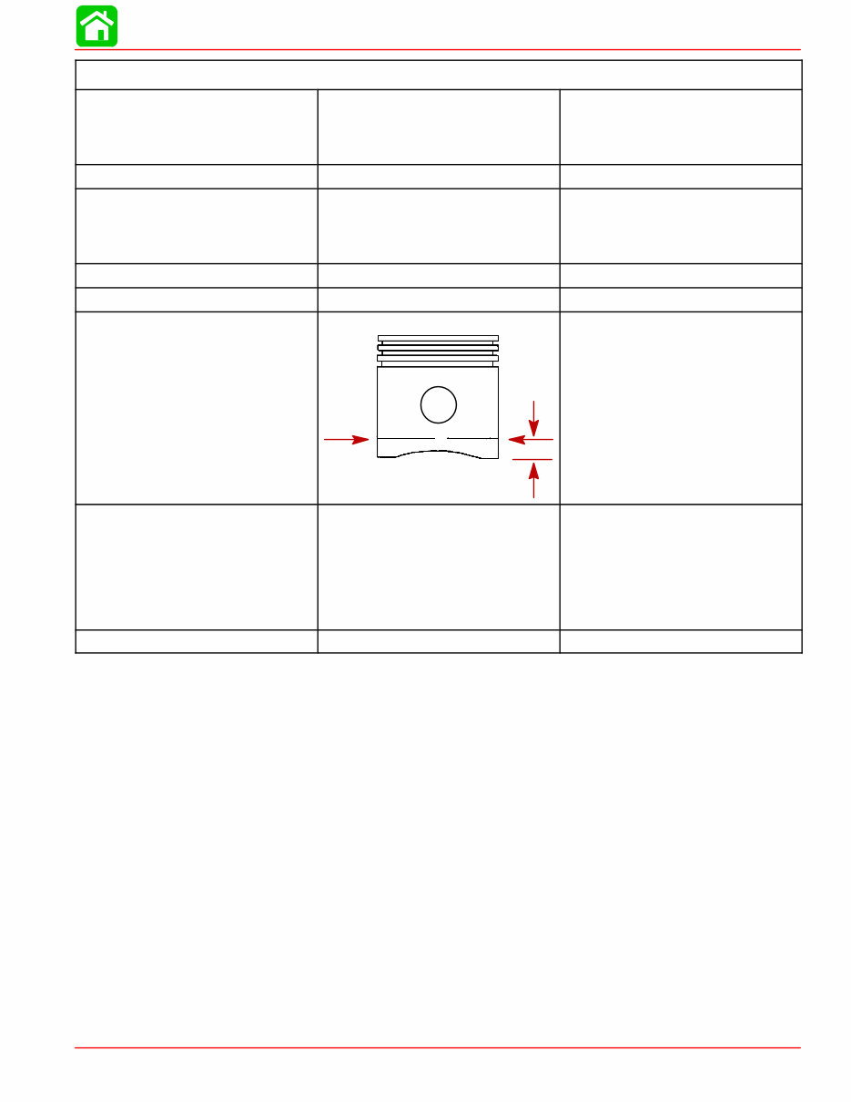
SPECIFICATIONS Page 1A-5 90-888438 JUNE 2002 Model 250 Optimax Jet Air Compressor Type Compressor Output Reciprocating Piston (1 to 1 ratio with engine RPM) @ Idle – 80 psi (551.6 kPa) @ W.O.T. – 110 psi (758.4 kPa) Cylinder Block Displacement 7.07 cu. in. (116 cc) Cylinder Bore Diameter (Standard) Taper/Out-of-Round/Wear Maxi- mum Bore Type 2.5591 in. (65.0 mm) 0.001 in. (0.025 mm) Cast Iron Stroke Length 1.374 in. (34.9 mm) Piston Piston Type Aluminum Piston Diameter Dimen- sion “A” at Right Angle (90°) to Piston Pin 0.500 in. 2.5578 ± .0004 in. (64.97 ± 0.010 mm) Piston Ring End Gap Top Ring Middle Ring Bottom Ring 0.0059 - 0.0098 in. (0.15 - 0.25 mm) 0.0059 - 0.0098 in. (0.15 - 0.25 mm) 0.0039 - 0.014 in. (0.10 - 0.35 mm) Reeds Reed Stand Open 0.010 in. (0.25 mm)
SPECIFICATIONS Page 1A-6 90-888438 JUNE 2002 Torque Chart PUMP UNIT Special Items Torque Inlet Screen Screw (6 mm) 75 lb. in. (8.5 Nm) Inlet Screen Screw (8 mm) 16.5 lb. ft. (22.4 Nm) Reverse Gate Stop Screw 120 lb. in. (13.6 Nm) Steering Lever Screw 15 lb. ft. (20.3 Nm) Pinion Shaft Housing Screw 15 lb. ft. (20.3 Nm) Drive Housing Cover Nuts 35 lb. ft. (47.5 Nm) Nozzle to Stator Bolts 35 lb. ft. (47.5 Nm) Stator Bolts 35 lb. ft. (47.5 Nm) Rudder Pivot Bolt 50 lb. ft. (68 Nm) Reverse Gate Pivot Bolt 80 lb. ft. (108.5 Nm) Impeller Gear Nut 90 lb. ft. (122 Nm) Impeller Nut 150 lb. ft. (203.4 Nm) POWERHEAD Special Items Torque Vapor Separator 140 lb. in. (15.8 Nm) Air Handler Assembly 100 lb. in. (11.3 Nm) Crank Case Cover Bolts M8x1.25x35 (14 ea) 20.8 lb. ft. (28.3 Nm) Crank Case Cover Bolts M10x1.5x80 (8 ea) 30 lb. ft. (40.6 Nm) Then Turn Additional 90° Expansion Chamber Nuts 20 lb. ft. (27.1 Nm) Connecting Rod Screws *30 lb. ft. (40.6 Nm) Then Turn Additional 90° Spark Plug 20 lb. ft. (27.1 Nm) Cylinder Head *20 lb.ft. (27.1 Nm) Then Turn Additional 90° Adaptor Plate to Powerhead 35 lb. ft. (47.5 Nm) Powerhead to Drive Housing Nuts 35 lb. ft. (47.5 Nm) Flywheel Nut 125 lb. ft. (169.5 Nm) *NOTE: Screws should not be reused after removal
After payment, MyGreenManuals.com is your number one source for repair manuals. Our informative repair manuals, owner's manuals, and parts catalogs contain all the information you'll need to perform repairs, look up parts, or do routine maintenance on your machine. You will have access to information regarding the following topics:
General Information
Routine Maintenance
Engine Removal and Installation
Fuel System
Lubrication and Cooling System
Engine Specifications
Transmission, Drive Chain & Sprockets
Steering System
Shocks
Body Work
Intake & Exhaust
Electrical System
Advanced Troubleshooting
With our repair manuals, find the page pertaining to your job, print it off, and get working on your machine. No more ruining your expensive paper shop manual with grease and dirt.
Broke down on the trail or site and have a smartphone? With our repair manuals, you instantly have access to the material needed to get you running again. Kind of tough to do that with a paper manual. And did we mention the fact that you're saving the trees?
All our repair manuals come with a lifetime protection policy. If lost or damaged, simply contact us, and we'll replace it free of charge for life.
We provide various repair service manuals, workshop manuals, repair manuals, owner's manuals, parts catalogs, and other various manuals for UTVs, motorcycles, ATVs, quads, snowmobiles, Seadoo, equipment, small engines, inboards, outboards, and more, all in an electronic format.




 Lifetime Access




