1984 Mercury Model 9.8 2-Stroke Outboard Service & Repair Manual
What's Included?
Lifetime Access
Fast Download Speeds
Online & Offline Access
Access PDF Contents & Bookmarks
Full Search Facility
Print one or all pages of your manual
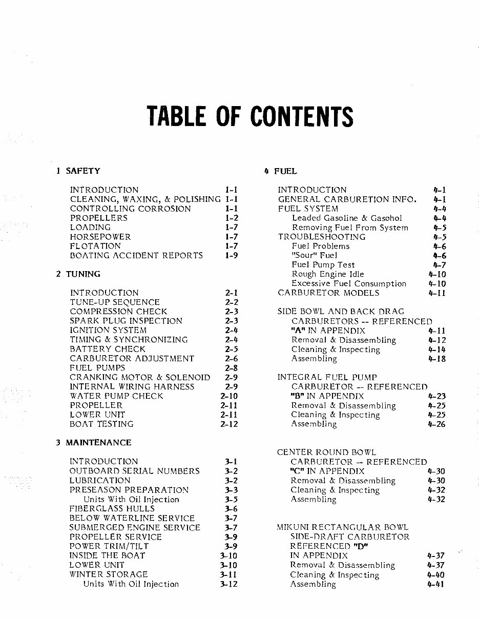
TABLE OF CONTENTS 1 SAFETY 1J FUEL INTRODUCTION 1-1 INTRODUCTION IJ-1 CLEANING, WAXING, & POLISHING 1-1 GENERAL CARBURETION INFO. IJ-1 CONTROLLING CORROSION 1-1 FUEL SYSTEM IJ-4 PROPELLERS 1-2 Leaded Gasoline & Gasohol IJ-4 LOADING 1-7 Removing Fuel From System "-5 HORSEPOWER 1-7 TROUBLESHOOTING "-5 FLOTATION 1-7 Fuel Problems 4-6 BOATING ACCIDENT REPORTS 1-9 "Sour" Fuel IJ-6 Fuel Pump Test 4-7 2 TUNING Rough Engine Idle "-10 Excessive Fuel Consumption IJ-10 INTRODUCTION 2-1 CARBURETOR MODELS IJ-11 TUNE-UP SEQUENCE 2-2 COMPRESSION CHECK 2-3 SIDE BOWL AND BACK DRAG SPARK PLUG INSPECTION 2-3 CARBURETORS-REFERENCED IGNITION SYSTEM 2-4 "A" IN APPENDIX 4-11 TIMING & SYNCHRONIZING 2-4 Removal & Disassembling 4-12 BATTERY CHECK 2-5 Cleaning & Inspecting IJ-14 CARBURETOR ADJUSTMENT 2-6 Assembling IJ-18 FUEL PUMPS 2-8 CRANKING MOTOR & SOLENOID 2-9 INTEGRAL FUEL PUMP INTERNAL WIRING HARNESS 2-9 CARBURETOR--REFERENCED WATER PUMP CHECK 2-10 "B" IN APPENDIX 11-23 PROPELLER 2-11 Removal & Disassembling 11-25 LOWER UNIT 2-11 Cleaning & Inspecting IJ-25 BOAT TESTING 2-12 Assembling IJ-26 3 MAINTENANCE CENTER ROUND BOWL INTRODUCTION 3-1 CARBURETOR -- REFERENCED OUTBOARD SERIAL NUMBERS 3-2 "C" IN APPENDIX "-30 LUBRICATION 3-2 Removal & Disassembling IJ-30 PRESEASON PREPARATION 3-3 Cleaning & Inspecting IJ-32 Units With Oil Injection 3-5 Assembling IJ-32 FIBERGLASS HULLS 3-6 BELOW WATERLINE SERVICE 3-7 SUBMERGED ENGINE SERVICE 3-7 MIKUNI RECTANGULAR BOWL PROPELLER SERVICE 3-9 SIDE-DRAFT CARBURETOR POWER TRIM/TILT 3-9 REFERENCED "D" INSIDE THE BOAT 3-10 IN APPENDIX IJ-37 LOWER UNIT 3-10 Removal & Disassembling 4-37 WINTER STORAGE 3-11 Cleaning & Inspecting IJ-40 Units With Oil Injection 3-12 Assembling IJ-41
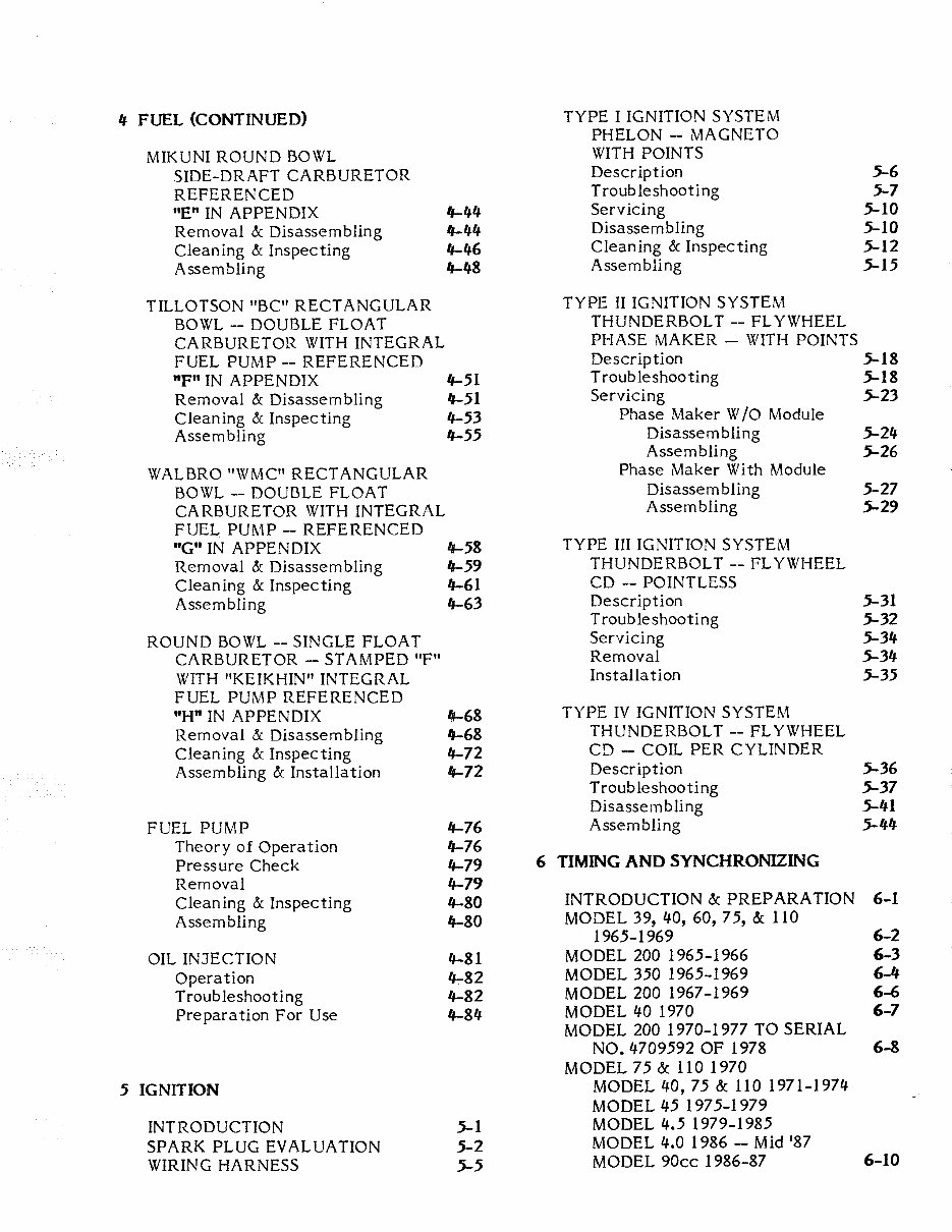
4 FUEL (CONTINUED) TYPE I IGNITION SYSTEM PHELON - MAGNETO MIKUNI ROUND BOWL WITH POINTS SIDE-DRAFT CARBURETOR Description .5-6 REFERENCED Troubleshooting .5-7 "E" IN APPENDIX IJ-44 Servicing .5-10 Removal & Disassembling IJ-44 Disassembling .5-10 Cleaning & Inspecting IJ-46 Cleaning & Inspecting .5-12 Assembling IJ-48 Assembling .5-15 TILLOTSON "BC" RECTANGULAR TYPE II IGNITION SYSTEM BOWL-- DOUBLE FLOAT THUNDERBOLT--FLYWHEEL CARBURETOR WITH INTEGRAL PHASE MAKER- WITH POINTS FUEL PUMP-- REFERENCED Description .5-18 "F" IN APPENDIX IJ-51 Troubleshooting .5-18 Removal & Disassembling IJ-51 Servicing .5-23 Cleaning & Inspecting IJ-53 Phase Maker W /0 Module Assembling IJ-55 Disassembling .5-24 Assembling .5-26 WALBRO "WMC" RECTANGULAR Phase Maker With Module BOWL-- DOUBLE FLOAT Disassembling 5-27 CARBURETOR WITH INTEGRAL Assembling .5-29 FUEL PUMP-- REFERENCED "G" IN APPENDIX IJ-58 TYPE III IGNITION SYSTEM Removal & Disassembling IJ-59 THUNDERBOLT--FLYWHEEL Cleaning & Inspecting IJ-61 CD --POINTLESS Assembling IJ-63 Description .5-31 Troubleshooting .5-32 ROUND BOWL-- SINGLE FLOAT Servicing .5-34 CARBURETOR --STAMPED "F" Removal .5-34 WITH "KEIKHIN" INTEGRAL Installation .5-35 FUEL PUMP REFERENCED "H" IN APPENDIX 4-68 TYPE IV IGNITION SYSTEM Removal & Disassembling IJ-68 THUNDERBOLT--FLYWHEEL Cleaning & Inspecting IJ-72 CD - COIL PER CYLINDER Assembling & Installation IJ-72 Description .5-36 Troubleshooting .5-37 Disassembling .5-41 FUEL PUMP IJ-76 Assembling .5-44 Theory of Operation IJ-76 Pressure Check IJ-79 6 TIMING AND SYNCHRONIZING Removal IJ-79 Cleaning & Inspecting IJ-80 INTRODUCTION & PREPARATION 6-1 Assembling IJ-80 MODEL 39, 40, 60, 75, & 110 1965-1969 6-2 OIL INJECTION IJ-81 MODEL 200 1965-1966 6-3 Operation 4-82 MODEL 350 1965-1969 6-4 Troubleshooting IJ-82 MODEL 200 1967-1969 6-6 Preparation For Use IJ-84 MODEL 40 1970 6-7 MODEL 200 1970-1977 TO SERIAL NO. 4709592 OF 1978 6-8 MODEL 75 & 110 1970 5 IGNITION MODEL 40, 75 & 110 1971-1974 MODEL 45 1975-1979 INTRODUCTION .5-1 MODEL 4.5 1979-1985 SPARK PLUG EVALUATION .5-2 MODEL 4.0 1986 --Mid '87 WIRING HARNESS 5-5 MODEL 90cc 1986-87 6-10
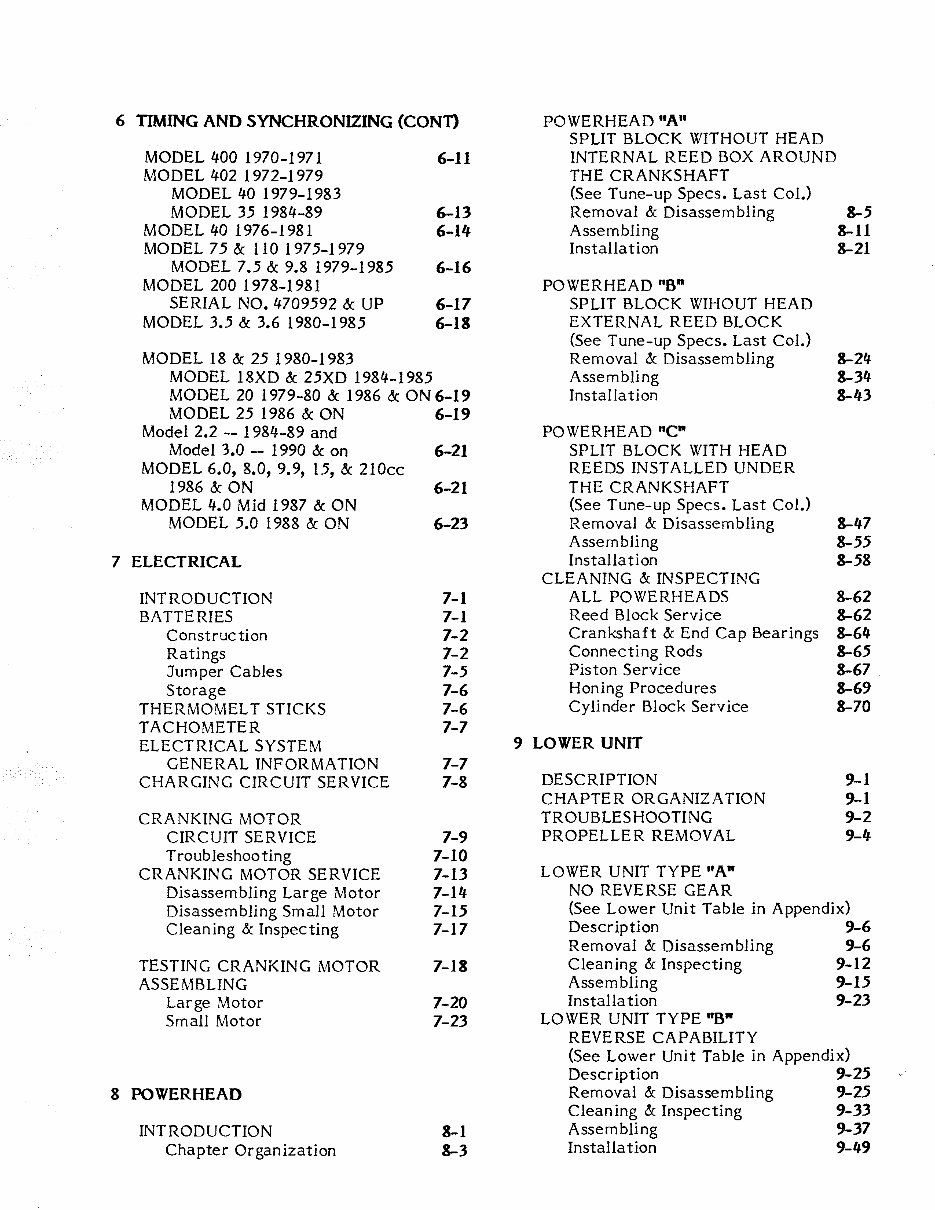
6 TIMING AND SYNCHRONIZING (CONn POWERHEAD "A" SPLIT BLOCK WITHOUT HEAD MODEL 400 1970-1971 6-11 INTERNAL REED BOX AROUND MODEL 402 1972-1979 THE CRANKSHAFT MODEL 40 1979-1983 (See Tune-up Specs. Last Col.) MODEL 35 1984-89 6-13 Removal & Disassembling &-5 MODEL 40 1976-1981 6-14 Assembling 8-11 MODEL 75 & 110 1975-1979 Installation &-21 MODEL 7.5 & 9.8 1979-1985 6-16 MODEL 200 1978-1981 POWERHEAD "8° SERIAL NO. 4709592 & UP 6-17 SPLIT BLOCK WIHOUT HEAD MODEL 3.5 & 3.6 1980-1985 6-18 EXTERNAL REED BLOCK (See Tune-up Specs. Last Col.) MODEL 18 & 25 1980-1983 Removal & Disassembling &-24 MODEL 18XD & 25XD 1984-1985 Assembling &-34 MODEL 20 1979-80 & 1986 & ON 6-19 Installation 8-43 MODEL 25 1986 & ON 6-19 Model 2.2 -- 1984-89 and POWERHEAD "C 0 Model 3.0 -- 1990 & on 6-21 SPLIT BLOCK WITH HEAD MODEL 6.0, 8.0, 9.9, 15, & 210cc REEDS INSTALL ED UNDER 1986 & ON 6-21 THE CRANKSHAFT MODEL 4.0 Mid 1987 & ON (See Tune-up Specs. Last Col.) MODEL 5.0 1988 & ON 6-23 Removal & Disassembling &-47 Assembling &-55 7 ELECTRICAL Installation &-58 CLEANING & INSPECTING INTRODUCTION 7-1 ALL POWERHEADS 8-62 BATTERIES 7-1 Reed Block Service 8-62 Construction 7-2 Crankshaft & End Cap Bearings 8-64 Ratings 7-2 Connecting Rods &-65 Jumper Cables 7-5 Piston Service &-67 Storage 7-6 Honing Procedures 8-69 THERMOMEL T STICKS 7-6 Cylinder Block Service 8-70 TACHOMETER 7-7 ELECTRICAL SYSTEM 9 LOWER UNIT GENERAL INFORMATION 7-7 CHARGING CIRCUIT SERVICE 7-8 DESCRIPTION 9-1 CHAPTER ORGANIZATION 9-1 CRANKING MOTOR TROUBLESHOOTING 9-2 CIRCUIT SERVICE 7-9 PROPELLER REMOVAL 9-4 Troubleshooting 7-10 CRANKING MOTOR SERVICE 7-13 LOWER UNIT TYPE "A" Disassembling Large Motor 7-14 NO REVERSE GEAR Disassembling Small Motor 7-15 (See Lower Unit Table in Appendix) Cleaning & Inspecting 7-17 Description 9-6 Removal & Disassembling 9-6 TESTING CRANKING MOTOR 7-18 Cleaning & Inspecting 9-12 ASSEMBLING Assembling 9-15 Large Motor 7-20 Installation 9-23 Small Motor 7-23 LOWER UNIT TYPE "B" REVERSE CAPABILITY (See Lower Unit Table in Appendix) Description 9-25 8 POWERHEAD Removal & Disassembling 9-25 Cleaning & Inspecting 9-33 INTRODUCTION &-1 Assembling 9-37 Chapter Organization &-3 Installation 9-49
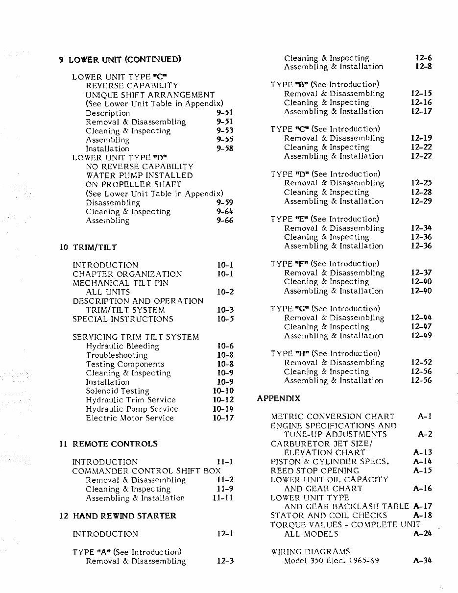
9 LOWER UNIT (CONTINUED) LOWER UNIT TYPE "C" REVERSE CAPABILITY UNIQUE SHIFT ARRANGEMENT (See Lower Unit Table in Appendix) Description 9-51 Removal & Disassembling 9-51 Cleaning & Inspecting 9-53 Assembling 9-55 Installation 9-58 LOWER UNIT TYPE "D" NO REVERSE CAPABILITY WATER PUMP INSTALLED ON PROPELLER SHAFT (See Lower Unit Table in Appendix) Disassembling 9-59 Cleaning & Inspecting 9-64 Assembling 9-66 10 TRIM/TILT INTRODUCTION 10-1 CHAPTER ORGANIZATION 10-1 MECHANICAL TILT PIN ALL UNITS 10-2 DESCRIPTION AND OPERATION TRIM/TILT SYSTEM 10-3 SPECIAL INSTRUCTIONS 10-5 SERVICING TRIM TILT SYSTEM Hydraulic Bleeding Troubleshooting Testing Components Cleaning & Inspecting lnstalla ti on Solenoid Testing Hydraulic Trim Service Hydraulic Pump Service Electric Motor Service 11 REMOTE CONTROLS 10-6 10-8 10-8 10-9 10-9 10-10 10-12 10-14 10-17 INTRODUCTION 11-1 COMMANDERCONTROLSHWTBOX Removal & Disassembling 11-2 Cleaning & Inspecting 11-9 Assembling & Installation 11-11 12 HAND REWIND STARTER INTRODUCTION TYPE "A" (See Introduction) Removal & Disassembling 12-1 12-3 Cleaning & Inspecting Assembling & Installation TYPE "B• (See Introduction) Removal & Disassembling Cleaning & Inspecting Assembling & Installation TYPE "C• (See Introduction) Removal & Disassembling Cleaning & Inspecting Assembling & Installation TYPE "D" (See Introduction) Removal & Disassembling Cleaning & Inspecting Assembling & Installation TYPE "E" (See Introduction) Removal & Disassembling Cleaning & Inspecting Assembling & Installation TYPE "F" (See Introduction) Removal & Disassembling Cleaning & Inspecting Assembling & Installation TYPE "G" (See Introduction) Removal & Disassembling Cleaning & Inspecting Assembling & Installation TYPE "H" (See Introduction) Removal & Disassembling Cleaning & Inspecting Assembling & Installation APPENDIX METRIC CONVERSION CHART ENGINE SPECIFICATIONS AND TUNE-UP ADJUSTMENTS CARBURETOR JET SIZE/ ELEVATION CHART PISTON & CYLINDER SPECS. REED STOP OPENING LOWER UNIT OIL CAPACITY AND GEAR CHART LOWER UNIT TYPE 12-6 12-8 12-15 12-16 12-17 12-19 12-22 12-22 12-25 12-28 12-29 12-34 12-36 12-36 12-37 12-40 12-40 12-44 12-47 12-49 12-52 12-56 12-56 A-1 A-2 A-13 A-14 A-15 A-16 AND GEAR BACKLASH TABLE A-17 STATOR AND COIL CHECKS A-18 TORQUE VALUES- COMPLETE UNIT ALL MODELS A-24 WIRING DIAGRAMS Model 350 Elec. 1965-69 A-34
Model 402 Manual 1976-78; Model 40 Manual 1979-81 A-34 Model 60 Elec. 1965-68; Model 110 Elec. 1965-69; Model 200 Elec. 1965-71 A-35 Model 400 Elec. 1970-71 A-36 Model 200 Elec. 1972 A-37 Model 402 Elec. 1972-74 A-38 Model 200 Elec. 1973-75 A-39 Model 200 w/ Alternator 1973-78 A-39 Model 200 Elec. 1976-78; Model 20 (20hp) 1979-80 A-40 Model 7 5 &: 110 Manual 197 5; Model 40 Manual 1976-80 A-41 Model 7 5 &: 110 Manual w/ Alternator 1976-78 Model 7.5 and Model 9.8 w/Alternator 1979-85 A-41 Model 7 5 &: 110 1 976-78; Model 7.5 &: 9.8 w/o Alternator 1979-85 A-42 Model 4-0 Manual 1970-74-; Model 4-.5 1979-85; Model 4.0 1986-Mid 1987 A-42 Model 4.0 Mid 1987 &: On; Model 5.0 1988 &: On and Model 90cc -- 1986-87 A-43 Model 402 Elec. 197 5; Model 40 1979-81 A-44 Model 402 Manual 1976-78; Model 40 Manual 1979-81 A-44 Model 18 Manual 1981-83; Model 18XD Manual 1984-85; Model 25 Manual 1980-83; Model 25XD Manual 1984-85; Model6.0, 8.0, 9.9, 15, 20, 25, 210cc Manual 1986 &: On A-45 Model 18 Elec. 1981-83; Model 18XD Elec. 1984-85; Model 25 Elec. 1980-83; Model 25XD Elec. 1984-85; Model 6.0, 8.0, 9. 9, 15, 20, 25, &: 21 Occ Elec. 1986 &: On All w/o Remote Control A-46 Model18 Elec. 1981-83; Model 18XD Elec. 1984-85; Model 25 Elec. 1980-83; Model 25XD Elec. 1984-85; Model6.0, 8.0, 9.9, 15, 20, 25, &: 21 Occ Elec. 1986 &: On All w/Remote Control A-47 Model 35 Manual 1984-89 and Model 40 Manual 1982-83 A-48 Model 35 Elec. -- 1984-89; Model 40 Elec. -- 1982-83 A-49 Model 3.5 -- 1983-85; Model 3.6 -- 1980-82 A-50 Model 2.2 -- 1984-89 and Model 3.0- 1990 &: On A-50 Commander Remote Control A-51
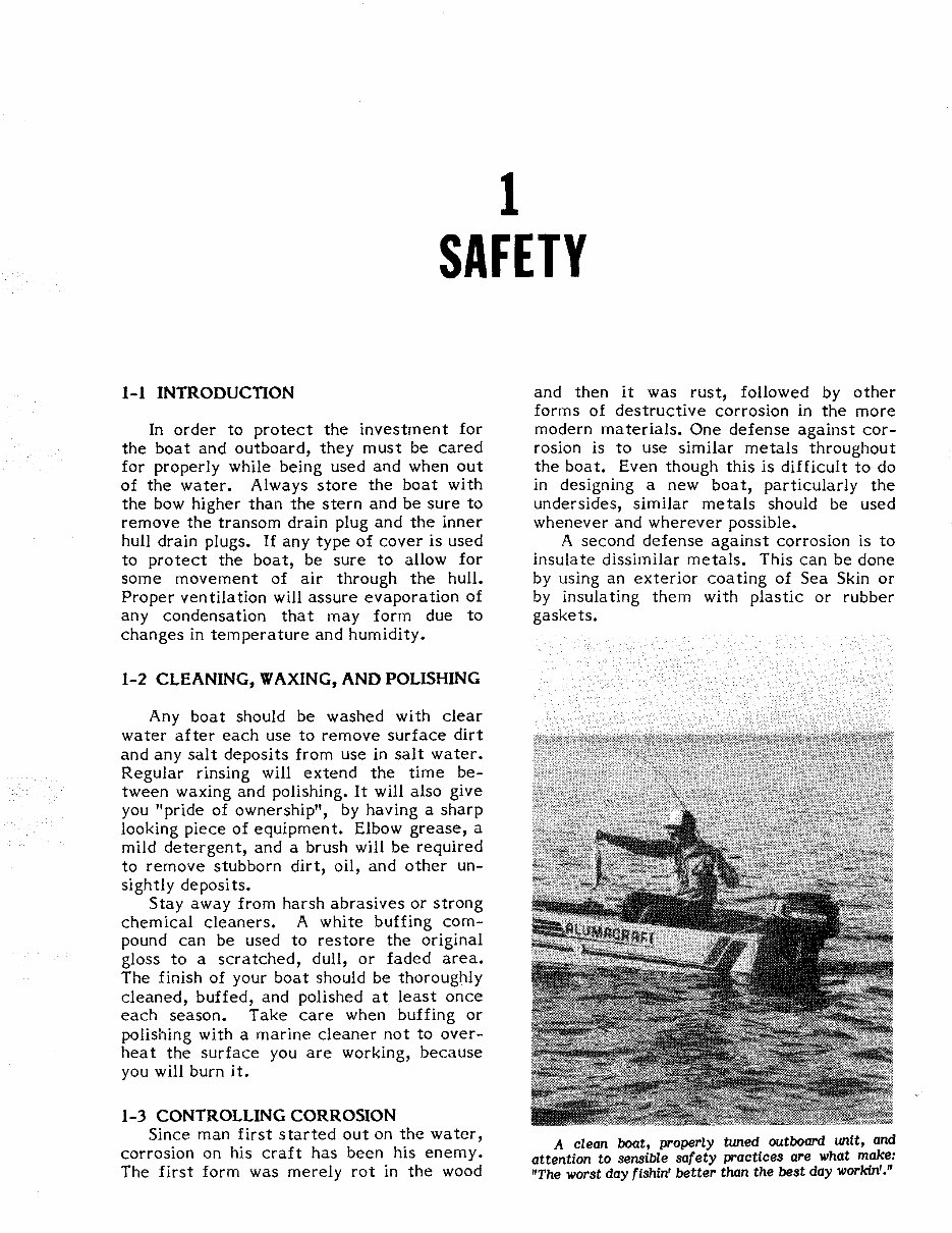
1 SAFETY 1-1 INTRODUCTION In order to protect the investment for the boat and outboard, they must be cared for properly while being used and when out of the water. Always store the boat with the bow higher than the stern and be sure to remove the transom drain plug and the inner hull drain plugs. If any type of cover is used to protect the boat, be sure to allow for some movement of air through the hull. Proper ventilation will assure evaporation of any condensation that may form due to changes in temperature and humidity. 1-2 CLEANING, WAXING, AND POLISHING Any boat should be washed with clear water after each use to remove surface dirt and any salt deposits from use in salt water. Regular rinsing will extend the time be- tween waxing and polishing. It will also give you "pride of ownership", by having a sharp looking piece of equipment. Elbow grease, a mild detergent, and a brush will be required to remove stubborn dirt, oil, and other un- sightly deposits. Stay away from harsh abrasives or strong chemical cleaners. A white buffing com- pound can be used to restore the original gloss to a scratched, dull, or faded area. The finish of your boat should be thoroughly cleaned, buffed, and polished at least once each season. Take care when buffing or polishing with a marine cleaner not to over- heat the surface you are working, because you will burn it. 1-3 CONTROLLING CORROSION Since man first started out on the water, corrosion on his craft has been his enemy. The first form was merely rot in the wood and then it was rust, followed by other forms of destructive corrosion in the more modern materials. One defense against cor- rosion is to use similar metals throughout the boat. Even though this is difficult to do in designing a new boat, particularly the undersides, similar metals should be used whenever and wherever possible. A second defense against corrosion is to insulate dissimilar metals. This can be done by using an exterior coating of Sea Skin or by insulating them with plastic or rubber gaskets. A clean boat, properly tuned outboard unit, and attention to sensible safety practices are what make: "The worst day fishin' better than the best day workin'."
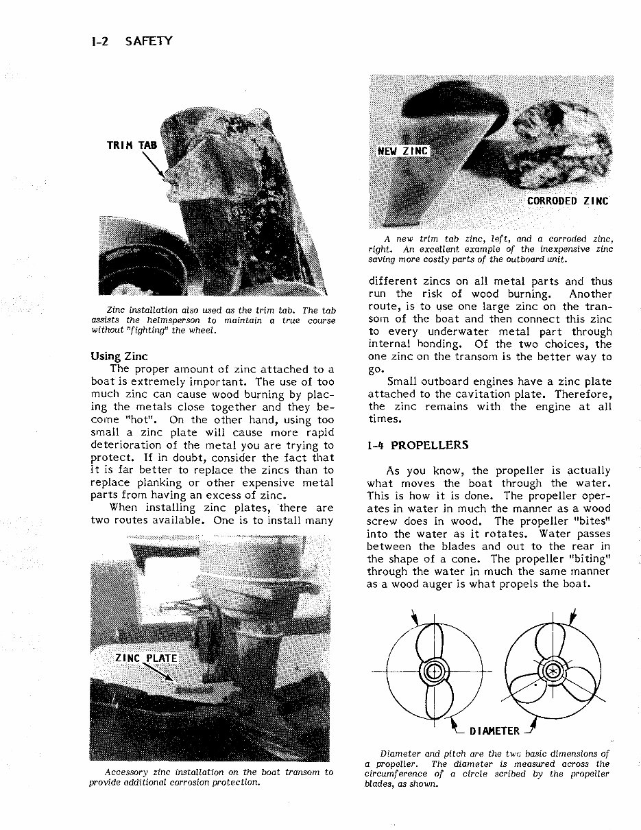
1-2 SAFETY Zinc installation also used as the trim tab. The tab assists the helmsperson to maintain a true course without "fighting" the wheel. Using Zinc The proper amount of zinc attached to a boat is extremely important. The use of too much zinc can cause wood burning by plac- ing the metals close together and they be- come "hot". On the other hand, using too small a zinc plate will cause more rapid deterioration of the metal you are trying to protect. If in doubt, consider the fact that it is far better to replace the zincs than to replace planking or other expensive metal parts from having an excess of zinc. When installing zinc plates, there are two routes available. One is to install many Accessory zinc installation on the boat transom to provide additional corrosion protection. A new trim tab zinc, left, and a corroded zinc, right. An excellent example of the inexpensive zinc saving more costly parts of the outboard unit. different zincs on all metal parts and thus run the risk of wood burning. Another route, is to use one large zinc on the tran- som of the boat and then connect this zinc to every underwater metal part through internal honding. Of the two choices, the one zinc on the transom is the better way to go. Small outboard engines have a zinc plate attached to the cavitation plate. Therefore, the zinc remains with the engine at all times. 1-4 PROPELLERS As you know, the propeller is actually what moves the boat through the water. This is how it is done. The propeller oper- ates in water in much the manner as a wood screw does in wood. The propeller "bites" into the water as it rotates. Water passes between the blades and out to the rear in the shape of a cone. The propeller "biting" through the water in much the same manner as a wood auger is what propels the boat. Diameter and pitch are the twu basic dimensions of a propeller. The diameter is measured across the circumference of a circle scribed by the propeller blades, as shown.
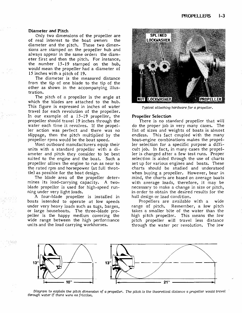
Diameter and Pitch Only two dimensions of the propeller are of real interest to the boat owner: the diameter and the pitch. These two dimen- sions are stamped on the propeller hub and always appear in the same order: the diam- eter first and then the pitch. For instance, the number 15-19 stamped on the hub, would mean the propeller had a diameter of 15 inches with a pitch of 19. The diameter is the measured distance from the tip of one blade to the tip of the other as shown in the accompanying illus- tration. The pitch of a propeller is the angle at which the blades are attached to the hub. This figure is expressed in inches of water travel for each revolution of the propeller. In our example of a 15-19 propeller, the propeller should travel 19 inches through the water each time it revolves. If the propel- ler action was perfect and there was no slippage, then the pitch multiplied by the propeller rpms would be the boat speed. Most outboard manufacturers equip their units with a standard propeller with a di- ameter and pitch they consider to be best suited to the engine and the boat. Such a propeller allows the engine to run as near to the rated rpm and horsepower (at full throt- tle) as possible for the boat design. The blade area of the propeller deter- mines its load-carrying capacity. A two- blade propeller is used for high-speed run- ning under very light loads. A four-blade propeller is installed in boats intended to operate at low speeds under very heavy loads such as tugs, barges, or large houseboats. The three-blade pro- peller is the happy medium covering the wide range between the high performance units and the load carrying workhorses. PROPELLERS 1-3 Typical attaching hardware for a propeller. Propeller Selection There is no standard propeller that will do the proper job in very many cases. The list of sizes and weights of boats is almost endless. This fact coupled with the many boat-engine combinations makes the propel- ler selection for a specific purpose a diffi- cult job. In fact, in many cases the propel- ler is changed after a few test runs. Proper selection is aided through the use of charts set up for various engines and boats. These charts should be studied and understood when buying a propeller. However, bear in mind, the charts are based on average boats with average loads, therefore, it may be necessary to make a change in size or pitch, in order to obtain the desired results for the hull design or load condition. Propellers are available with a wide range of pitch. Remember, a low pitch takes a smaller bite of the water than the high pitch propeller. This means the low pitch propeller will travel less distance through the water per revolution. The low 21" -------lloo-! Diagram to explain the pitch dimension of a propeller. The pitch is the theoretical distance a propeller would travel through water if there were no friction.
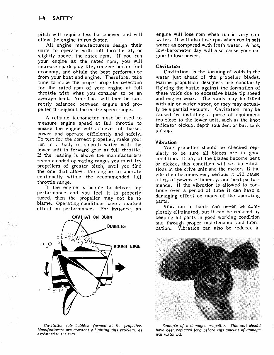
1-4 SAFETY pitch will require less horsepower and will allow the engine to run faster. All engine manufacturers design their units to operate with full throttle at, or slightly above, the rated rpm. If you run your engine at the rated rpm, you will increase spark plug life, receive better fuel economy, and obtain the best performance from your boat and engine. Therefore, take time to make the proper propeller selection for the rated rpm of your engine at full throttle with what you consider to be an average load. Your boat will then be cor- rectly balanced between engine and pro- peller throughout the entire speed range. A reliable tachometer must be used to measure engine speed at full throttle to ensure the engine will achieve full horse- power and operate efficiently and safely. To test for the correct propeller, make your run in a body of smooth water with the lower unit in forward gear at full throttle. If the reading is above the manufacturer's recommended operating range, you must try propellers of greater pitch, until you find the one that allows the engine to operate continually within the recommended full throttle range. If the engine is unable to deliver top performance and you feel it is properly tuned, then the propeller may not be to blame. Operating conditions have a marked effect on performance. For instance, an 0 0 0 0 Cavitation (air bubbles) formed at the propeller. Manufacturers are constantly fighting this problem, as explained in the text. engine will lose rpm when run in very cold water. It will also lose rpm when run in salt water as compared with fresh water. A hot, low-barometer day will also cause your en- gine to lose power. Cavitation Cavitation is the forming of voids in the water just ahead of the propeller blades. Marine propulsion designers are constantly fighting the battle against the formation of these voids due to excessive blade tip speed and engine wear. The voids may be filled with air or water vapor, or they may actual- ly be a partial vacuum. Cavitation may be caused by installing a piece of equipment too close to the lower unit, such as the knot indica tor pickup, depth sounder, or bait tank pickup. Vibration Your propeller should be checked reg- ularly to be sure all blades are in good condition. If any of the blades become bent or nicked, this condition will set up vibra- tions in the drive unit and the motor. If the vibration becomes very serious it will cause a loss of power, efficiency, and boat perfor- mance. If the vibration is allowed to con- tinue over a period of time it can have a damaging effect on many of the operating parts. Vibration in boats can never be com- pletely eliminated, but it can be reduced by keeping all parts in good working condition and through proper maintenance and lubri- cation. Vibration can also be reduced in Example of a damaged propeller. This unit should have been replaced long before this amount of damage was sustained.
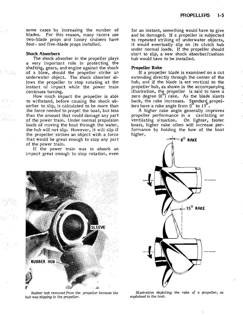
some cases by increasing the number of blades. For this reason, many racers use two-blade props and luxury cruisers have four- and five-blade props installed. Shock Absorbers The shock absorber in the propeller plays a very important role in protecting the shafting, gears, and engine against the shock of a blow, should the propeller strike an underwater object. The shock absorber al- lows the propeller to stop rotating at the instant of impact while the power train continues turning. How much impact the propeller is able to withstand, before causing the shock ab- sorber to slip, is calculated to be more than the force needed to propel the boat, but less than the amount that could damage any part of the power train. Under normal propulsion loads of moving the boat through the water, the hub will not slip. However, it will slip if the propeller strikes an object with a force that would be great enough to stop any part of the power train. If the power train was to absorb an impact great enough to stop rotation, even Rubber hub removed from the propeller because the hub was slipping in the propeller. PROPELLERS 1-5 for an instant, something would have to give and be damaged. If a propeller is subjected to repeated striking of underwater objects, it would eventually slip on its clutch hub under normal loads. If the propeller should start to slip, a new shock absorber/cushion hub would have to be installed. Propeller Rake If a propeller blade is examined on a cut extending directly through the center of the hub, and if the blade is set vertical to the propeller hub, as shown in the accompanying illustration, the propeller is said to have a zero degree (0°) rake. As the blade slants back, the rake increases. Sbandar<& propel- lers have a rake angle from 0 to 15 • A higher rake angle generally improves propeller performance in a cavitating or ventilating situation. On lighter, faster boats, higher rake often will increase per- formance by holding the bow of the boat higher. nzustration depicting the rake of a propeller, as explained in the text.
1984 Mercury Model 9.8 2-Stroke Outboard Service & Repair Manual
The 1984 Mercury Model 9.8 2-Stroke Outboard Service & Repair Manual provides detailed maintenance and repair guidance for Mercury’s compact 9.8 horsepower 2-stroke marine engine. Tailored for boat owners, mechanics, and service professionals, this manual covers all major systems specific to the 9.8hp model for the 1984 model year.
From ignition timing and fuel troubleshooting to lower unit servicing and remote starter operation, this manual offers clear technical explanations and procedures to help with both routine servicing and more involved repairs. The included sections walk you through powerhead inspection, carburetor tuning, magneto ignition servicing, and recoil starter assembly — all written with clarity and accuracy for confident DIY repairs.
Content Overview:
Tune-up, compression, and ignition system testing
Mikuni & Tillotson carburetor removal and reassembly
Fuel pump repair and fuel system troubleshooting
Flywheel magneto and CD ignition diagnostics
Lower unit removal, disassembly, and reinstallation
Powerhead disassembly and crankshaft bearing inspection
Pull-start (hand starter) rope replacement and repair
Trim/tilt adjustment and hydraulic troubleshooting
Electrical system diagrams and charging circuit testing
This manual is ideal for maintaining or restoring your 1984 Mercury 9.8hp 2-stroke engine. Whether you're fixing a hard-starting issue, inspecting the water pump, or replacing ignition components, you'll find the step-by-step detail you need to keep your motor running strong.
Printable: Yes Language: English Compatibility: Pretty much any electronic device Requirements: Adobe Reader (free)
Recently Viewed
5,521,897Happy Clients
2,594,462eManuals
1,120,453Trusted Sellers
15Years in Business
Price:
Actual Price:
1984 Mercury Model 9.8 2-Stroke Outboard Service & Repair Manual