TILLER HANDLE Page 7B-4 90-856159R1 AUGUST 1998 Throttle Cable/Linkage Installation and Adjustment Throttle Cables SIDE SHIFT MODELS 1. Rotate the tiller twist grip to full counterclockwise position. a a- Wide Open Throttle Position 2. Rotate pulley to align the pointer with the match mark on the bracket as shown below. b a a- Pulley Pointer b- Match Mark
TILLER HANDLE 90-856159R1 AUGUST 1998 Page 7B-5 3. Install longest cable barrel into anchor “a”. 4. Wrap longest cable into inner groove around top side of pulley. Place cable jacket into upper anchor bracket. a c b a- Anchor “a” b- Cable Jacket c- Upper Anchor Bracket 5. Rotate tiller twist grip to full clockwise (idle) position. 6. Install remaining barrel into anchor “b”. 7. Place remaining cable into outer groove, wrap around to bottom side of pulley. Place cable jacket into lower anchor bracket. a b c d a- Remaining Cable b- Anchor “b” c- Cable Jacket d- Lower Anchor Bracket
TILLER HANDLE Page 7B-6 90-856159R1 AUGUST 1998 8. Position locking tab washer into respective tab slot and hole. a c b a a- Locking Tabs b- Tab Slot c- Tab Hole 9. Rotate throttle twist grip back to full counterclockwise (wide open throttle) position. 10. Adjust cable lengths using jam nuts to bring match marks into alignment, make adjust- ments to lower cable first. 11. Remove slack in upper cable by adjusting upper jam nuts. DO NOT OVERTIGHTEN. a b a- Upper Jam Nuts b- Lower Jam Nuts 12. Rotate tiller throttle handle from idle to wide open throttle to idle again. Verify match marks are in alignment [± 1/8″(3.175mm)]. Readjust jam nuts if marks are not aligned. FRONT SHIFT MODELS 1. Rotate the tiller twist grip to full counterclockwise position. a a- Wide Open Throttle Position
TILLER HANDLE 90-856159R1 AUGUST 1998 Page 7B-7 2. Rotate pulley to align the pointer with the match mark on the bracket as shown below. 56971 a b a- Pulley Pointer b- Match Mark 3. Install longest cable/barrel into anchor “a”. 4. Wrap longest cable into inner groove around top side of pulley. Place cable jacket into upper anchor bracket. 56972 a b c a- Anchor “a” b- Cable Jacket c- Upper Anchor Bracket 5. Install remaining barrel into anchor “b”. 6. Place remaining cable into outer groove, wrap around to bottom side of pulley. Place cable jacket into lower anchor bracket. 56973 a b c d a- Remaining Cable b- Anchor “b” c- Cable Jacket d- Lower Anchor Bracket
TILLER HANDLE Page 7B-8 90-856159R1 AUGUST 1998 7. Position locking tab washers into respective tab slot and hole. 8. Adjust cable lengths using jam nuts to bring match marks into alignment, make adjust- ments to lower cable first. 9. Remove slack in upper cable by adjusting upper jam nuts. DO NOT OVERTIGHTEN. 57013 56974 a a b b b c d a- Locking Tab Washers b- Tab Hole c- Upper Jam Nuts d- Lower Jam Nuts Linkage 1. Turn idle speed screw counterclockwise until screw is not touching throttle shaft arm. a b a- Idle Speed Screw b- Throttle Shaft Arm
TILLER HANDLE 90-856159R1 AUGUST 1998 Page 7B-9 2. Install throttle linkage on pulley and throttle barrel. a b 56974 c a a- Throttle Linkage b- Throttle Barrel c- Pulley 3. Check to make sure throttle linkage has free movement between throttle barrel and pulley. NOTE: The throttle arm should remain stationary while checking for free movement of throttle linkage. a b c a- Throttle Barrel b- Pulley c- Throttle Arm 4. Move throttle linkage forward until linkage comes to rest on the pulley boss. a b a- Throttle Linkage b- Pulley Boss
TILLER HANDLE Page 7B-10 90-856159R1 AUGUST 1998 5. Tighten screw on throttle barrel to secure linkage. NOTE: Over-tightening screw may damage throttle linkage. NOTE: Check linkage for free movement on pulley. Verify throttle shaft arm in not sticking and returns to idle position. a b a- Screw b- Linkage 6. Verify throttle arm does not hit the full throttle stop at wide open throttle. Gap between stop and throttle arm should be no more than 0.1 in. (2.54 mm). a b c a- Throttle Stop b- Throttle Arm c- Approximately 0.1 in. (2.54 mm) Gap 7. Turn idle speed screw in (clockwise) until it touches the throttle shaft arm, then turn an additional 1/2 turn for initial setting. a b a- Idle Speed Screw b- Throttle Shaft Arm
Applicable Serial Numbers: 0G590000 and above (United States)
The Mercury Mariner 9.9HP, 15HP 4-Stroke Outboards OEM Service & Repair Manual provides factory-level service information for standard and Bigfoot 4-stroke models. Covering engines from serial number 0G590000 and up, this manual is essential for professional marine technicians, DIY owners, and anyone looking to maintain or repair these popular mid-range outboards.
With detailed service procedures, precise torque specifications, and clear illustrations, the manual allows you to perform everything from routine maintenance tasks to complex repairs with confidence. Whether you're servicing the carburetor, repairing the gear housing, or troubleshooting electrical systems, this manual ensures you have the correct information at every step.
Content Overview:
General Information: Specifications, maintenance intervals, service basics, installation guidelines
Fuel System: Fuel pump maintenance, carburetor servicing, emission system components
Powerhead: Cylinder head and crankcase service, oil pump overhaul
Mid-Section: Steering components, exhaust passages, trim and tilt systems
Lower Unit: Gearcase repair for standard and Bigfoot configurations
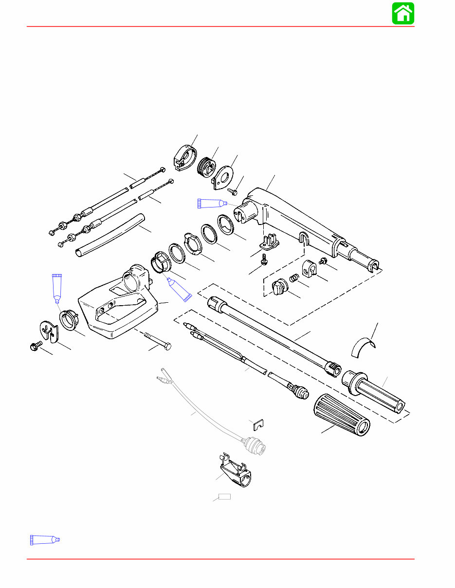
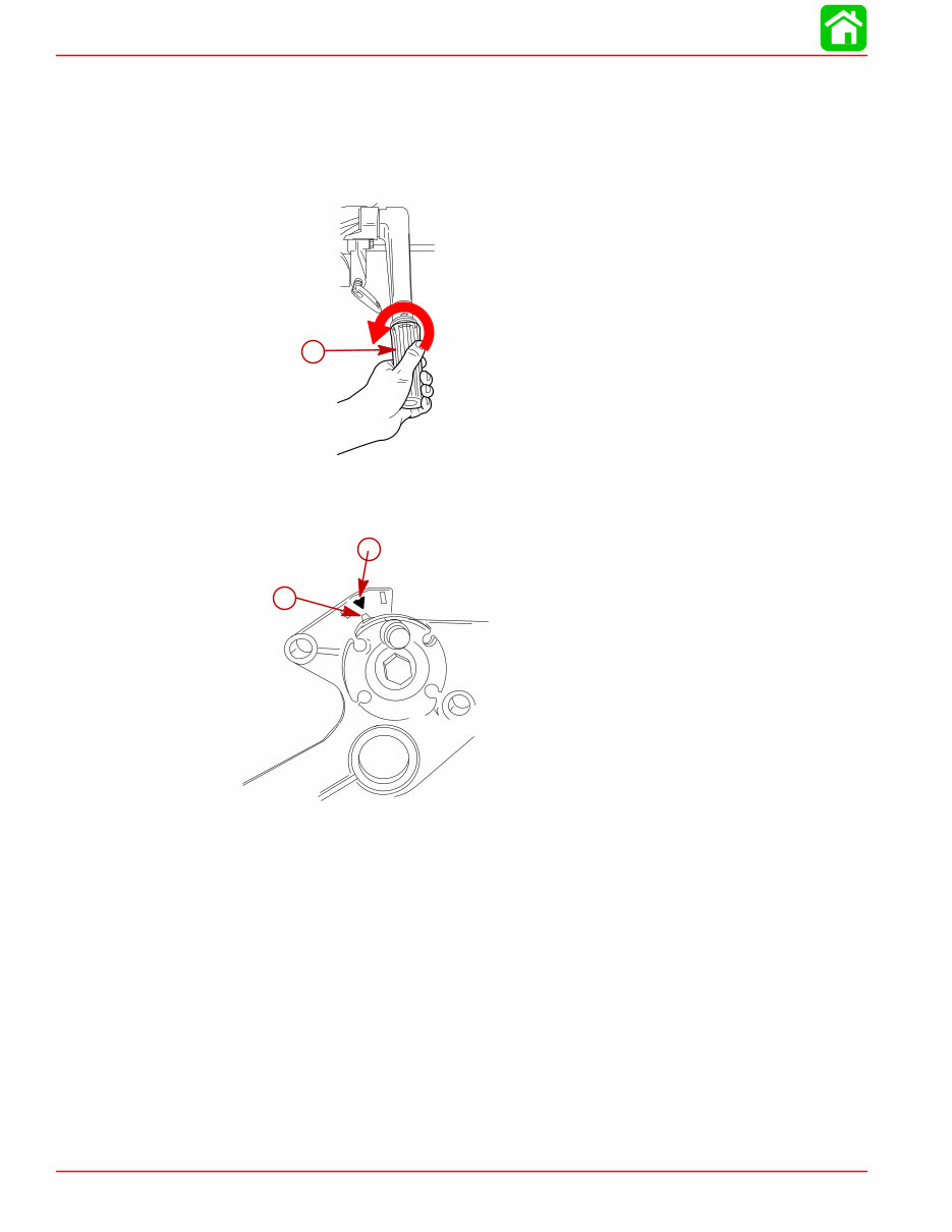
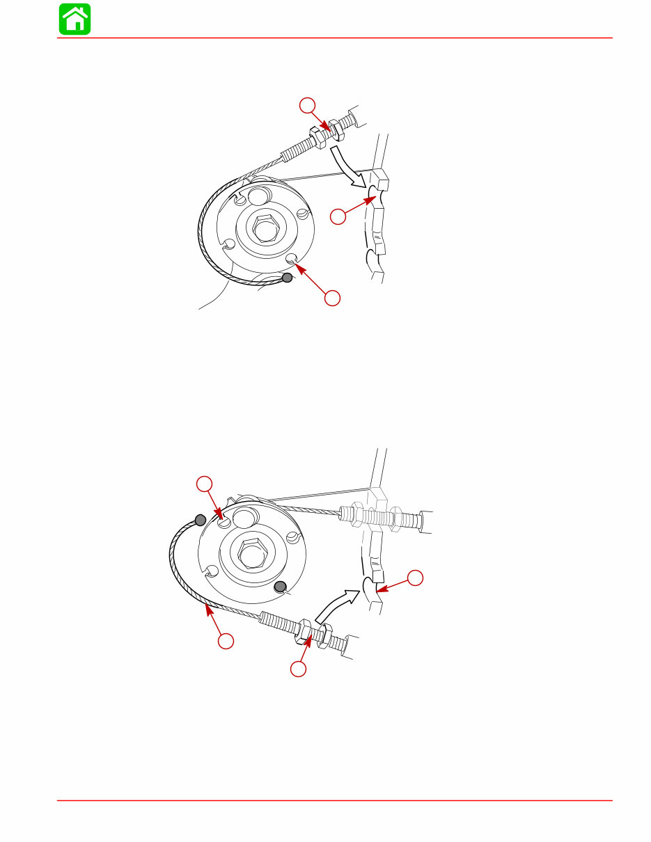
Control Linkage & Attachments: Throttle and shift controls, tiller handle maintenance
Manual Starter: Rope starter assembly and troubleshooting
Whether you're preparing for a season of boating or performing a full engine rebuild, this manual offers the trusted information needed to work efficiently and accurately. It’s the same service reference relied on by authorized Mercury dealers, now available for your personal workshop.
Printable: Yes Language: English Compatibility: Pretty much any electronic device, including PC & Mac computers, Android and Apple smartphones & tablets Requirements: Adobe Reader (free)