MODELS SERVICE MANUAL Mercury/Mariner 40·45·50·50 Bigfoot (4-Stroke) United States 0G231123 . . . . . . With Starting Serial Numbers Printed in U.S.A. 1999, Mercury Marine 90-828631R3 MARCH 1999 Downloaded from www.Manualslib.com manuals search engine
90-828631R3 MARCH 1999 Page i Notice Throughout this publication, “Dangers”, “Warnings” and “Cautions” (accompanied by the In- ternational HAZARD Symbol ) are used to alert the mechanic to special instructions con- cerning a particular service or operation that may be hazardous if performed incorrectly or carelessly. OBSERVE THEM CAREFULLY! These “Safety Alerts” alone cannot eliminate the hazards that they signal. Strict compliance to these special instructions when performing the service, plus “Common Sense” operation, are major accident prevention measures. DANGER DANGER - Immediate hazards which WILL result in severe personal injury or death. WARNING WARNING - Hazards or unsafe practices which COULD result in severe personal in- jury or death. CAUTION Hazards or unsafe practices which could result in minor personal injury or product or property damage. Notice to Users of This Manual This service manual has been written and published by the Service Department of Mercury Marine to aid our dealers’ mechanics and company service personnel when servicing the products described herein. It is assumed that these personnel are familiar with the servicing procedures of these prod- ucts, or like or similar products manufactured and marketed by Mercury Marine, that they have been trained in the recommended servicing procedures of these products which in- cludes the use of mechanics’ common hand tools and the special Mercury Marine or recom- mended tools from other suppliers. We could not possibly know of and advise the service trade of all conceivable procedures by which a service might be performed and of the possible hazards and/or results of each method. We have not undertaken any such wide evaluation. Therefore, anyone who uses a service procedure and/or tool, which is not recommended by the manufacturer, first must completely satisfy himself that neither his nor the products safety will be endangered by the service procedure selected. All information, illustrations and specifications contained in this manual are based on the latest product information available at the time of publication. As required, revisions to this manual will be sent to all dealers contracted by us to sell and/or service these products. It should be kept in mind, while working on the product, that the electrical system and ignition system are capable of violent and damaging short circuits or severe electrical shocks. When performing any work where electrical terminals could possibly be grounded or touched by the mechanic, the battery cables should be disconnected at the battery. Any time the intake or exhaust openings are exposed during service they should be covered to protect against accidental entrance of foreign material which could enter the cylinders and cause extensive internal damage when the engine is started. Downloaded from www.Manualslib.com manuals search engine
Page ii 90-828631R3 MARCH 1999 It is important to note, during any maintenance procedure replacement fasteners must have the same measurements and strength as those removed. Numbers on the heads of the met- ric bolts and on the surfaces of metric nuts indicate their strength. American bolts use radial lines for this purpose, while most American nuts do not have strength markings. Mis- matched or incorrect fasteners can result in damage or malfunction, or possibly personal injury. Therefore, fasteners removed should be saved for reuse in the same locations when- ever possible. Where the fasteners are not satisfactory for re-use, care should be taken to select a replacement that matches the original. Cleanliness and Care of Outboard Motor A marine power product is a combination of many machined, honed, polished and lapped surfaces with tolerances that are measured in the ten thousands of an inch/mm. When any product component is serviced, care and cleanliness are important. Throughout this manu- al, it should be understood that proper cleaning, and protection of machined surfaces and friction areas is a part of the repair procedure. This is considered standard shop practice even if not specifically stated. Whenever components are removed for service, they should be retained in order. At the time of installation, they should be installed in the same locations and with the same mating surfaces as when removed. Personnel should not work on or under an outboard which is suspended. Outboards should be attached to work stands, or lowered to ground as soon as possible. We reserve the right to make changes to this manual without prior notification. Refer to dealer service bulletins for other pertinent information concerning the products de- scribed in this manual. EXAMPLE: 90-826148 R1 JANUARY 1996 LOWER UNIT - 6A-7 Revision No. 1 Month of Printing Year of Printing Section Description Section Number Part of Section Letter Page Number Downloaded from www.Manualslib.com manuals search engine
1 2 3 4 5 6 7 9 Important Information Electrical Fuel System Powerhead Mid-Section Gear Housing Attachments/ Control Linkage 90-828631R3 MARCH 1999 Page iii Service Manual Outline Section 1 - Important Information A - Specifications B - Maintenance C - General Information D - Outboard Motor Installation Section 2 - Electrical A - Ignition B - Charging & Starting System C - Timing,Synchronizing & Adjusting D - Wiring Diagrams Section 3 - Fuel System A - Fuel Pump B - Carburetor C - Emissions Section 4 - Powerhead A - Cylinder Head B - Cylinder Block/Crankcase C - Lubrication Section 5 - Mid-Section A - Clamp/Swivel Brackets & Drive Shaft Housing B - Power Trim (1998 And Earlier Non-Bigfoot) C - Power Trim (1999 And Later Non-Bigfoot/ All Big-Foot Model Years) D - Manual Tilt Assist Section 6 - Gear Housing A - Non-Bigfoot Gear Housing B - Bigfoot Gear Housing Section 7 - Attachments/Control Linkage A - Throttle/Shift Linkage B - Tiller Handle Downloaded from www.Manualslib.com manuals search engine
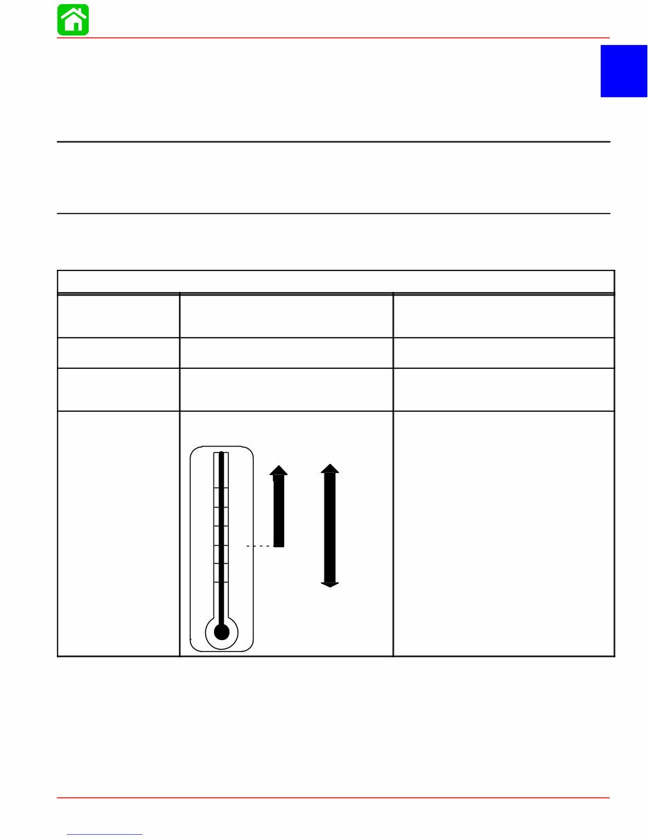
1 A SPECIFICATIONS 90-828631R3 MARCH 1999 Page 1A-1 IMPORTANT INFORMATION Section 1A - Specifications Table of Contents Specifications 1A-1 . . . . . . . . . . . . . . . . . . . . . . . . . . . . . Gear Case Design Identification 1A-7 . . . . . . . . . . . . . Propeller Information Charts 1A-8 . . . . . . . . . . . . . . . . Mercury/Mariner 50 (4-Stroke) 2.00:1 Non Bigfoot 1A-8 . . . . . . . . . . . . . . . . . . . . . . Mercury/Mariner 50 (4-Stroke) 1.83:1 Non Bigfoot 1A-9 . . . . . . . . . . . . . . . . . . . . . . Mercury/Mariner 50 (4-Stroke) 2.3:1 Bigfoot 1A-10 . . . . . . . . . . . . . . . . . . . . . . . . . . Specifications Models 40/45/50/50 (4-Stroke) HORSEPOWER (kW) Model 50 Model 45 Model 40 50 hp (37.3 Kw) @ 6000 rpm 45 hp (33.5 Kw) @ 6000 rpm 40 hp (29.8 Kw) @ 6000 rpm OUTBOARD WEIGHT Electric 40/45/50 ELPT 224 lb (102 kg) FUEL RECOMMENDED GASOLINE Automotive Unleaded with a Minimum Pump Posted Octane Rating of 87 OIL ENGINE OIL CAPACITY ENGINE OIL +20 +40 +60 +80 F° C° 0 +100 –7 +4 +16 +27 –18 +38 SAE 10W-30 SAE 25W-40 Either 3 Quarts or 3 Liters SAE 10W-30 viscosity oil is recom- mended for use in all temperatures. SAE 25W-40 viscosity oil may be used at temperatures above 40° F (4° C). Use Quicksilver 4-Cycle Marine Oil with the proper viscosity for the expected temperature in your area (see range thermometer on left). If not available, use a premium quality 4-cycle engine oil, cer- tified to meet or exceed anyone of the following American Petroleum Institute (API) service classification SH, SG, SF, CF-4, CE, CD, CDll. Downloaded from www.Manualslib.com manuals search engine
SPECIFICATIONS Page 1A-2 90-828631R3 MARCH 1999 IGNITION SYSTEM* *Readings taken @ 68°F (20°C). Type Spark Plug Type (NGK) Spark Plug Gap Firing Order Ignition Timing: 40/45 HP Fully Retarded Fully Advanced (2500-3000 rpm) 50 HP Fully Retarded Fully Advanced (2500-3000 rpm) Charge Coil Resistance Trigger Coil Resistance Ignition Coil Resistance: Primary Secondary cdi Engine Speed Limiter cdi Overheat Speed Control Engine Temperature Switch Above 131° F (55° C) Below 104° F (40° C) Capacitor Discharge Ignition NGK DPR6EA-9 0.035 in. (1.0 mm) 1-3-4-2 5° B.T.D.C 25° B.T.D.C 5° B.T.D.C 35° B.T.D.C 272 - 408 Ω (BRN-BLU) 396 - 594 Ω (WHT/BLK-WHT/RED) 0.1 - 0.7 Ω 3.5 - 4.7 kΩ 6120 - 6280 rpm 1600 - 2400 rpm No Continuity Continuity CHARGING SYSTEM Alternator Type Alternator Output: Electric Start Lighting Coil Resistance (Grn - Grn) Lighting Coil Output Peak Voltage Three Phase 12 Volts - 10 Amps. (Regulated) 1.2 - 3.2 Ohms @ 68°F (20°C) 8.9 Volts @ 1500 rpm STARTING SYSTEM P/N 50-825095 Top Mounted Electric Start: Starter Type Output Ampere Draw Under: (Load) (No Load) P/N 50-834749 Side Mounted Starter Type Output Ampere Draw Under: (Load) (No Load) Bendix 1.1 kW 106.0 Amps 21.1 Amps Bendix 1.1 kW 95.0 Amps 20.0 Amps BATTERY Battery Rating Minimum Requirement For operation below 32° F (0° C) 465 Marine Cranking Amps (MCA) or 350 Cold Cranking Amps (CCA). 1000 Marine Cranking Amps (MCA) or 775 Cold Cranking Amps (CCA) ENRICHMENT CONTROL SYSTEM Choke Solenoid Electro-thermal ram projection 3.2 - 4.8 Ω @ 68°F (20 °C) 0.3 in. (7 mm) after 5 min. of power FUEL SYSTEM Fuel Pump Type Fuel Pump: Pressure Diaphragm Stroke Plunger Stroke Fuel Tank Capacity External (Plunger/Diaphragm) 3-6 psi (21-41 kPa) 0.14 - 0.20 in. (3.5 - 5.1 mm) 0.23 - 0.38 in. (5.85 - 9.65 mm) Accessory Downloaded from www.Manualslib.com manuals search engine
SPECIFICATIONS 90-828631R3 MARCH 1999 Page 1A-3 CARBURETOR Idle rpm (Out Of Gear) 45 hp 40/50 hp Idle rpm (In Forward Gear) 45 hp 40/50 hp Wide Open Throttle rpm (WOT) Range Main Jet Size 40/45 hp Carburetors 1 and 2 Carburetors 3 and 4 50 hp Pilot Jet Float Height 950 ± 25 rpm 825 ± 25 rpm 850 ± 25 rpm 725 ± 25 rpm 5500–6000 rpm #104 #103 #112 #42 0.39 ± 0.02 in. (10.0 ± 0.5 mm) CYLINDER BLOCK Type Displacement Number of Cylinders 4 Stroke Cycle – Over Head Camshaft 57 cu. in. (935cc) 4 STROKE Length 2.953 in. (75 mm) CYLINDER BORE Diameter Standard Oversize-0.020 in. (0.050 mm) Taper/Out of Round Maximum Bore Type 2.4803 in. (63.0 mm) 2.5003 in. (63.5 mm) 0.003 in. (0.08 mm) Steel PISTON Piston Type O.D. at Skirt Standard Oversize-0.020 in. (0.50mm) Aluminum 2.4783-2.4789 in. (62.950-62.965 mm) 2.4983-2.4989 in. (63.450-63.465 mm) PISTON CLEARANCE Piston to Cylinder Clearance 0.0014 - .0026 in. (0.035 - 0.065 mm) RINGS Ring End Gap (Installed) Top Middle Bottom (Oil Ring) Side Clearance: Top Middle 0.006 - 0.012 in. (0.15 - 0.30 mm) 0.012 - 0.020 in. (0.30 - 0.50 mm) 0.008 - 0.028 in. (0.20 - 0.70 mm) 0.002 - 0.003 in. (0.04 - 0.08 mm) 0.001 - 0.003 in. (0.03 - 0.08 mm) COMPRESSION RATIO Compression Ratio Cylinder Compression (cold engine @ W.O.T.) 9.8:1 170 -190 lb/in 2 (Peak) PISTON PIN Piston Pin Diameter 0.6285-0.6287 in. (15.965 - 15.970 mm) CONNECTING ROD Oil Clearance (Big End) Small End Inside Diameter 0.0008 - 0.0020 in. (0.020 - 0.052 mm) 0.6293 - 0.6298 in. (15.985-15.998 mm) Downloaded from www.Manualslib.com manuals search engine
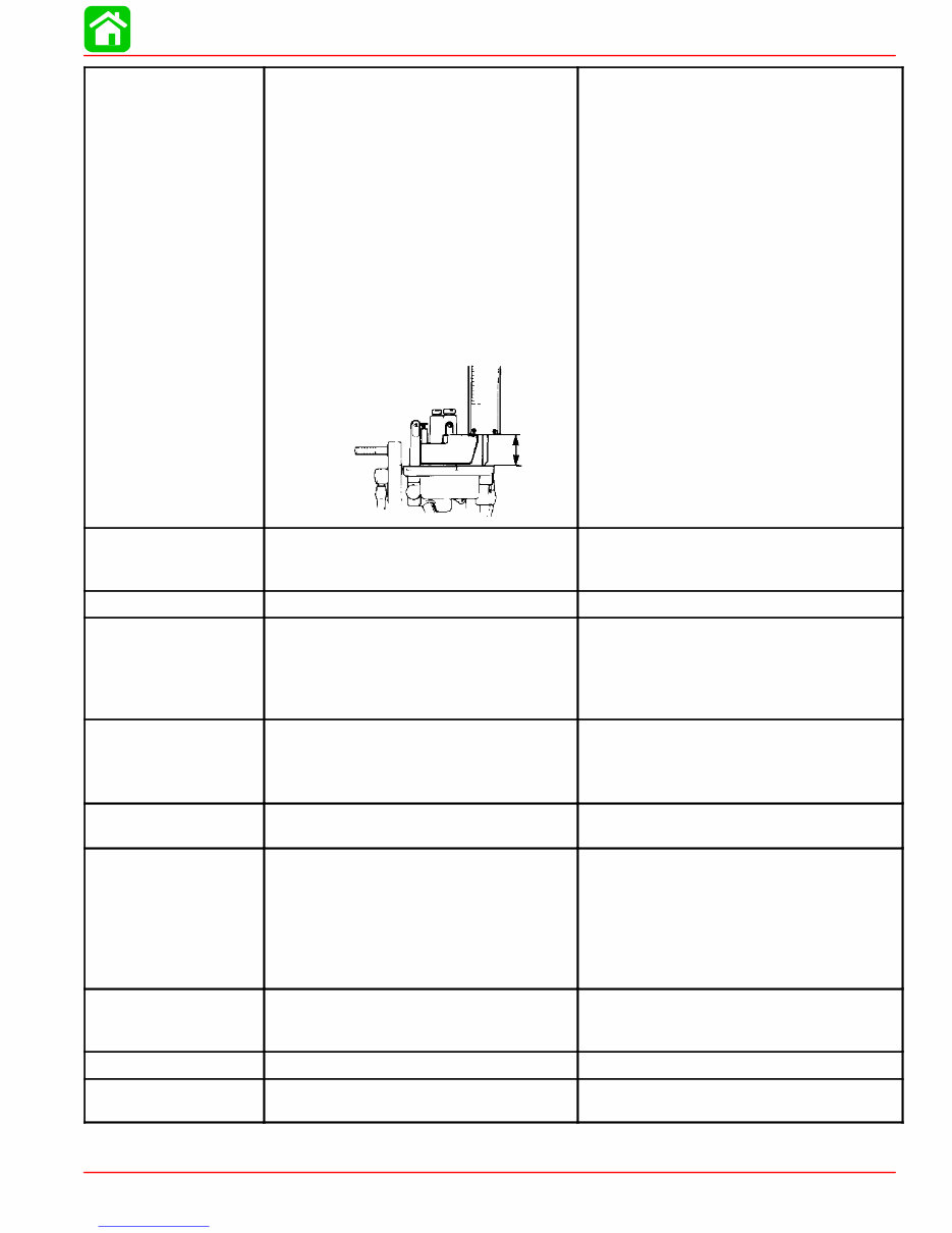
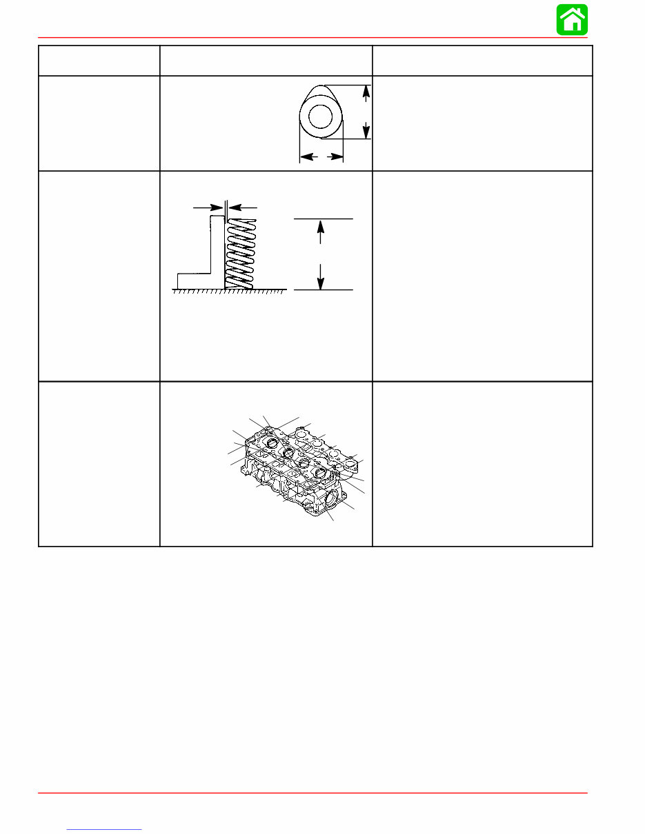
SPECIFICATIONS Page 1A-4 90-828631R3 MARCH 1999 CRANKSHAFT Main Bearing Clearance Crankshaft Run-out 0.0005 - 0.0017 in. (0.012 - 0.044 mm) 0.0012 in. (0.03 mm) CAMSHAFT Camshaft Dimensions Intake “A” Exhaust “A” Intake “B” Exhaust “B” Run-out Limit A B 1.216 - 1.220 in. (30.89 - 30.99 mm) 1.213 - 1.217 in. (30.82 - 30.92 mm) 1.022 - 1.025 in. (25.95 - 26.05 mm) 1.022 - 1.025 in. (25.95 - 26.05 mm) 0.0039 in. (0.1 mm) VALVE SPRING Free Length “a” Tilt Limit “b” Compressed Pressure (Installed) Intake Exhaust Tilt Limit (Intake & Exhaust) Dir. of Winding (Intake & Exhaust) a b 1.491-1.569 in. (37.85-39.85 mm) Less than 0.060 in. (1.7 mm) 19.8 - 22.0 lb (9.0 - 10.0 kg) 19.8 - 22.0 lb (9.0 - 10.0 kg) 0.043 in. (1.1 mm) Left Hand CYLINDER HEAD Warp Limit * Lines indicate straight edge measurement 0.004 in. (0.1 mm) Downloaded from www.Manualslib.com manuals search engine
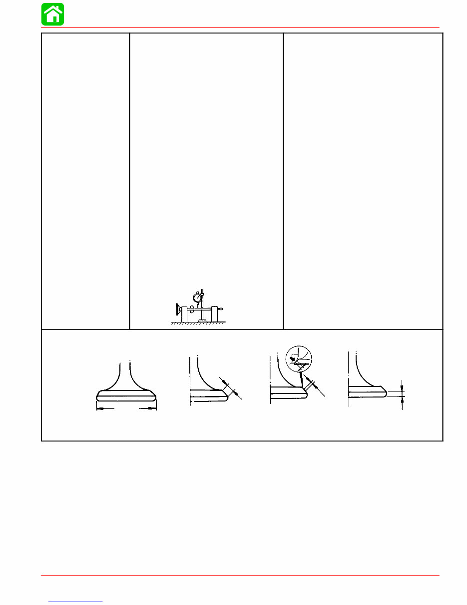
SPECIFICATIONS 90-828631R3 MARCH 1999 Page 1A-5 VALVES Valve/Valve Seat/Valve Guides: Valve Clearance (cold) Intake Exhaust Valve Dimensions: “A” Head Diameter Intake Exhaust “B” Face Width Intake Exhaust “C” Seat Width Intake Exhaust “D” Margin Thickness Intake Exhaust Stem Outside Diameter Intake Exhaust Guide Inside Diameter Intake Exhaust Stem To Guide Clearance Intake Exhaust Stem Run-out Limit (max.) 0.006 - 0.010 in. (0.15 - 0.25 mm) 0.010 - 0.014 in. (0.25 - 0.35 mm) 1.177 - 1.185 in. (29.9 - 30.1 mm) 1.020 - 1.028 in. (25.9 - 26.1 mm) 0.079 - 0.124 in. (2.00 - 3.14 mm) 0.079 - 0.124 in. (2.00 - 3.14 mm) 0.035 - 0.043 in. (0.9 - 1.1 mm) 0.035 - 0.043 in. (0.9 - 1.1 mm) 0.020 - 0.035 in. (0.5 - 0.9 mm) 0.020 - 0.035 in. (0.5 - 0.9 mm) 0.2156 - 0.2161 in. (5.475 - 5.490 mm) 0.2150 - 0.2156 in. (5.460 - 5.475 mm) 0.2165 - 0.2170 in. (5.500 - 5.512 mm) 0.2165 - 0.2170 in. (5.500 - 5.512 mm) 0.0004 - 0.0015 in. (0.010 - 0.037 mm) 0.0010 - 0.0020 in. (0.025 - 0.052 mm) 0.0006 in. (0.016 mm) “A” “B” “C” “D” Valve Dimensions Head Diameter Face Width Seat Width Margin Thickness Downloaded from www.Manualslib.com manuals search engine
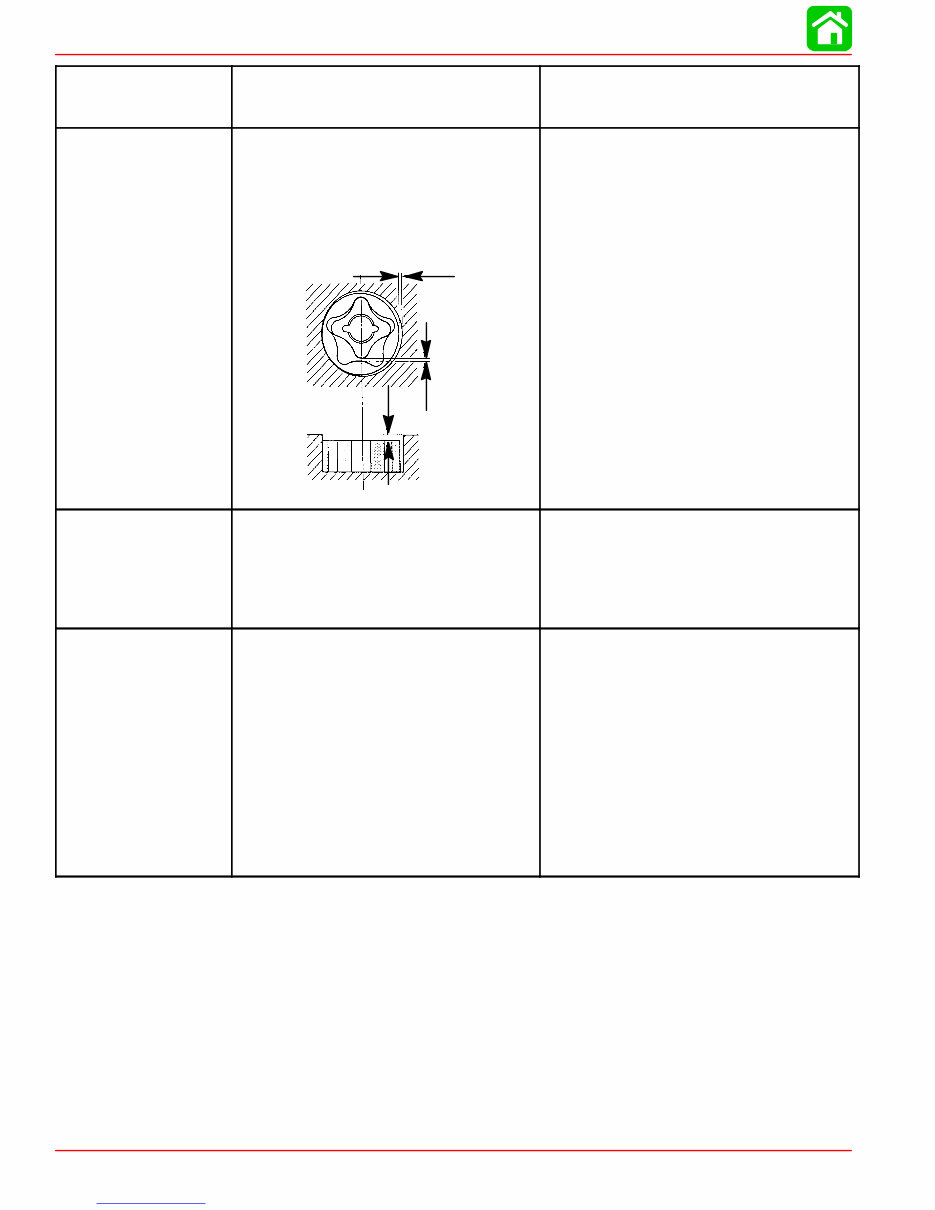
SPECIFICATIONS Page 1A-6 90-828631R3 MARCH 1999 THERMOSTAT Valve Opening Temperature Full Open Temperature Valve Lift 136° F - 143° F (58° C - 62° C) 158° F (70° C) 0.12 in. (3 mm) LUBRICATION SYSTEM Pump Type Engine Oil Pressure Engine Oil Pan Capacity Oil Pump: Outer Rotor to Housing “a” Inner Rotor to Outer Rotor “b” Rotor to Housing “c” a b c Trochoid 30-40 psi at 3000 rpm (Warm Engine) Either 3 Qts. or 3 Liters 0.001 - 0.006 in. (0.03 - 0.15 mm) 0.005 in. (0.12 mm) 0.001 - 0.003 in. (0.03 - 0.08 mm) MID-SECTION Transom Height: Long Shaft Steering Pivot Range Tilt Pin Positions Full Tilt Up Angle Allowable Transom Thickness 20 in. (51 cm) 90° 5 + Shallow Water 70° 2-3/8 in. (60.3 mm) 1995/1996 GEAR HOUSING (2.00:1) 45/50 1995/1996 models Gear Ratio Gearcase Capacity Lubricant Type Forward Gear Number of Teeth Pinion Gear Number of Teeth Pinion Height Forward Gear Backlash Water Pressure @ Idle @ WOT 2.00:1 14.9 fl oz (440 mL) Quicksilver Gear Lube-Premium Blend 26 Spiral/Bevel 13 Spiral/Bevel 0.025 in. (0.64 mm) No Adjustment 2-4 psi (14-28 kPa) @ 750 rpm 12-17 psi (83-117 kPa) @ 6000 rpm Downloaded from www.Manualslib.com manuals search engine
Get instant access to the Mercury Mariner 40/45/50/50 Bigfoot (4-Stroke) Outboard OEM Service & Repair Manual without any extra fees or expiry dates. This Professional Manual is ideal for both professional mechanics, technicians, and DIY enthusiasts. It is fully updated to cover all repairs, servicing, and troubleshooting procedures specifically for Mercury Mariner models, featuring detailed photos, diagrams, step-by-step instructions, and highly detailed exploded diagrams and pictures to ensure every job is completed correctly.
Print out a single page or the entire manual according to your needs. This Manual can be installed and used on multiple computers with no limitations or trial periods, and it does not expire or require any renewal fees, running seamlessly on all Windows and MAC computers.
OEM Service and Repair information for Mercury Mariner 40/45/50/50 Bigfoot (4-Stroke) Outboards
Comprehensive step-by-step repair procedures with full color illustrations
Detailed technical data and exploded diagrams for accurate troubleshooting
User-friendly format for both professionals and DIY enthusiasts