

7
C
OUTBOARD
INSTALLATION/
ATTACHMENTS
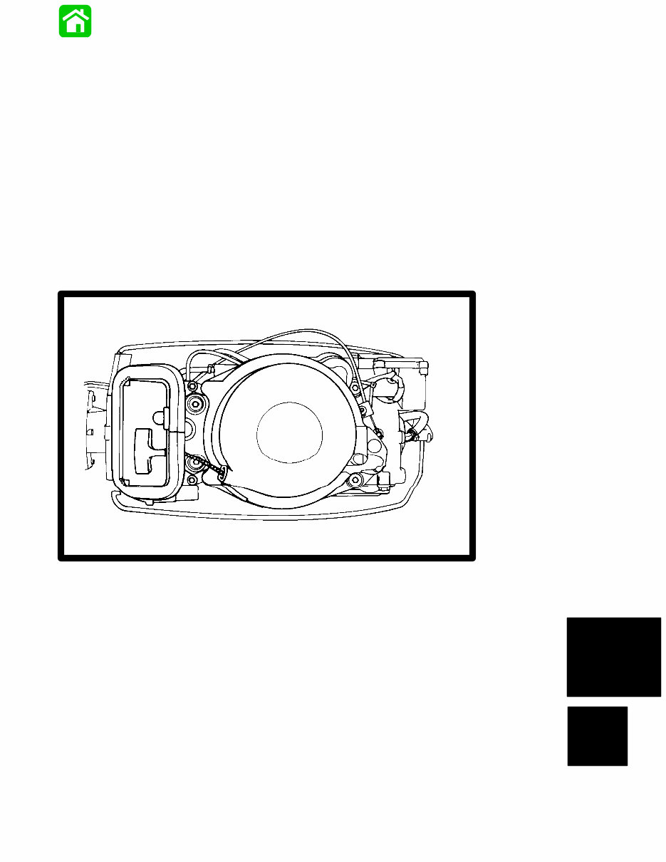
REWIND STARTER

7C-0 - OUTBOARD INSTALLATION/ATTACHMENTS 90-817643R1 DECEMBER 1996
Table of Contents
Page
Notes 7C-1 . . . . . . . . . . . . . . . . . . . . . . . . . . . . . . . . . . . . . . . .
Rewind Starter Components 7C-2 . . . . . . . . . . . . . . . . . . . .
Rewind Starter Disassembly 7C-4 . . . . . . . . . . . . . . . . . . . .
Cleaning and Inspection 7C-4 . . . . . . . . . . . . . . . . . . . . .
Rewind Starter Reassembly 7C-5 . . . . . . . . . . . . . . . . . . . .
Adjusting Rewind Spring Tension 7C-6 . . . . . . . . . . . . .
Starter Interlock Cable Adjustment 7C-7 . . . . . . . . . . . .

OUTBOARD INSTALLATION/ATTACHMENTS - 7C-1 90-817643R1 DECEMBER 1996
Notes:
7C-2 - OUTBOARD INSTALLATION/ATTACHMENTS 90-817643R1 DECEMBER 1996
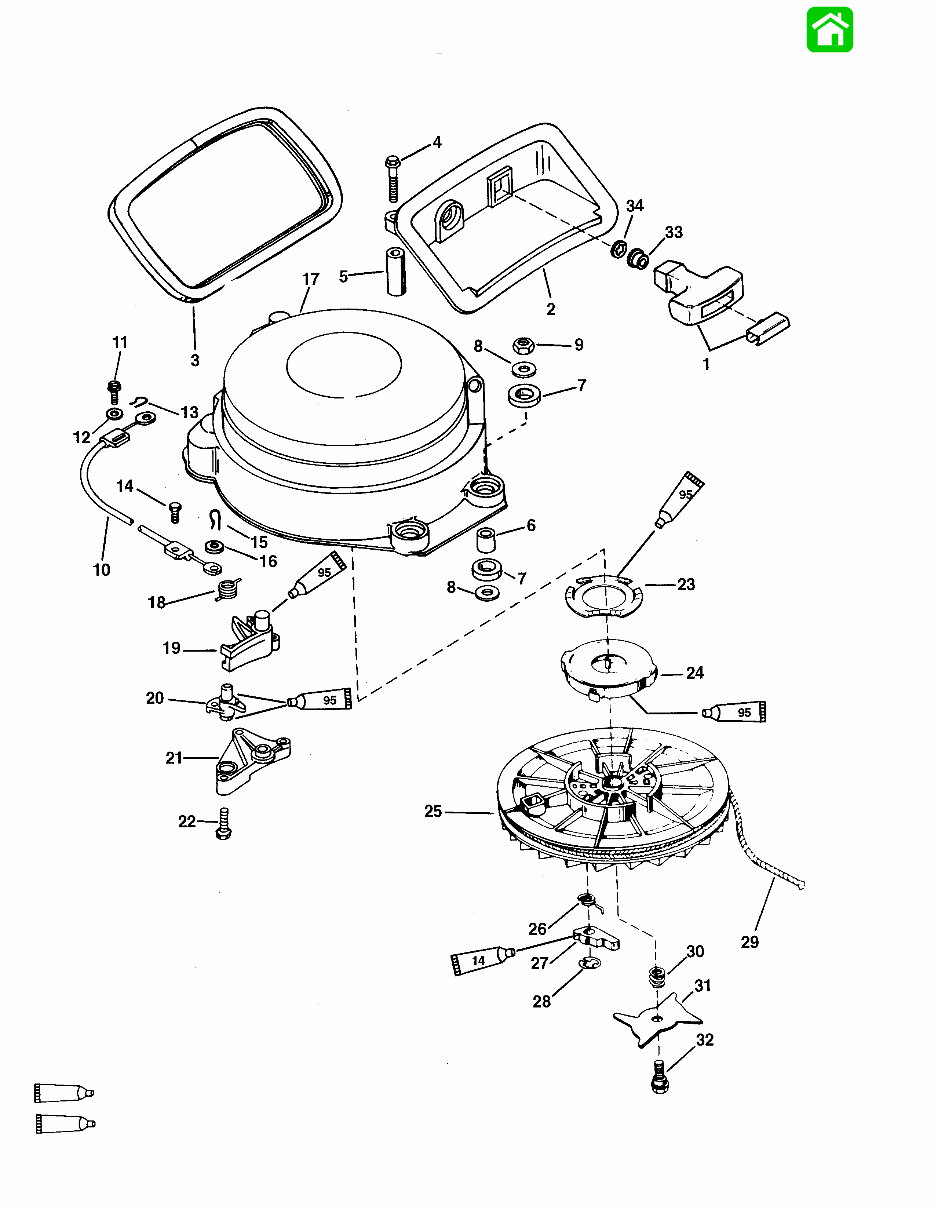
Starter Assembly (MANUAL – 55)
95
2-4-C With Teflon (92-825407A12)
14
2 Cycle Outboard Oil (92-13249A24)

OUTBOARD INSTALLATION/ATTACHMENTS - 7C-3 90-817643R1 DECEMBER 1996
Starter Assembly (MANUAL – 55)
REF.
TORQUE
REF .
NO. QTY. DESCRIPTION lb. in. lb. ft. N·m
1 1 HANDLE ASSEMBLY
2 1 REST
3 1 SEAL
4 2 SCREW 55 6.0
5 2 SPACER
6 4 BUSHING
7 8 GROMMET
8 8 WASHER
9 4 NUT 75 8.5
10 1 INTERLOCK CABLE
11 1 SCREW Drive Tight
12 1 WASHER
13 1 COTTER PIN
14 1 SCREW Drive Tight
15 1 COTTER PIN
16 1 WASHER
– 1 RECOIL STARTER
17 1 STARTER HOUSING
18 1 SPRING
19 1 INTERLOCK LEVER
20 1 CAM
21 1 RETAINER
22 3 SCREW
23 1 WASHER - SPRING
24 1 SPRING
25 1 STARTER SHEAVE
26 2 SPRING
27 2 CAM
28 2 RETAINING RING
29 1 STARTER ROPE
30 1 SPRING
31 1 CAM
32 1 SCREW
33 1 BUSHING
34 1 RETAINING RING
You're Reading a Preview
What's Included?
Fast Download Speeds
Offline Viewing
Access Contents & Bookmarks
Full Search Facility
Print one or all pages of your manual
$36.99
Mercury Mariner Outboard 45 50 55 60 Big Foot Factory Service Repair Manual
Viewed 34 Times Today

What's Included?
Fast Download Speeds
Offline Viewing
Access Contents & Bookmarks
Full Search Facility
Print one or all pages of your manual
$36.99

Secure transaction
What's Included?
Fast Download Speeds
Offline Viewing
Access Contents & Bookmarks
Full Search Facility
Print one or all pages of your manual
Description
This service manual for the Mercury Mariner Outboard 45 50 55 60 Big Foot is the same type used by local dealers for repairs. It contains detailed illustrations, diagrams, wiring schematics, and step-by-step instructions. The manual covers general information & specifications, electrical & ignition, fuel systems, power trim, lower unit, jet drive, outboard installation/attachments, and more. It is useful for both professional mechanics and DIY enthusiasts.
File Format: PDF
Printable: Yes
Languages: English
Compatible: Win/Mac
Requirements: Adobe Reader
Tons of pictures and diagrams are included, and all pages are printable for easy access in the home, office, or repair shop.


