

GENERAL INFORMATION
AND SPECIFICATIONS
1

90-13645-2 495
Table Of Contents
Page Page
General Specification 1-1 . . . . . . . . . . . . . . . . . . . . . .
Cowl Removal 1-3 . . . . . . . . . . . . . . . . . . . . . . . . . . . .
Filling Oil Injection System 1-3 . . . . . . . . . . . . . . . . . .
Power Trim General Information 1-4 . . . . . . . . . . . . .
Trim “In” Angle Adjustment 1-4 . . . . . . . . . . . . . . . . .
Models with Power Trim 1-4 . . . . . . . . . . . . . . . .
Checking Trim System Fluid Level 1-5 . . . . . . . . . . .
Tilt Angle Adjustment 1-5 . . . . . . . . . . . . . . . . . . . . . .
Models without Power Trim 1-5 . . . . . . . . . . . . . .
Connecting Engine Wiring Harness and
Routing of Engine Battery Cables 1-6 . . . . . . . .
Ride-Guide Steering Cable and
Pivot Points Lubrication 1-7 . . . . . . . . . . . . . . . . .
Following Complete Submersion 1-8 . . . . . . . . . . . .
Salt Water Submersion
(Special Instructions) 1-8 . . . . . . . . . . . . . . . .
Submerged While Running
(Special Instructions) 1-8 . . . . . . . . . . . . . . . .
Submerged Engine (Fresh Water)
(Plus Special Instructions) 1-8 . . . . . . . . . . .
Out-of-Season Outboard Storage 1-9 . . . . . . . . . . .
How Weather Affects Engine Performance 1-10 . .
Conditions Affecting Operation 1-11 . . . . . . . . . . . . .
Detonation: Causes and Prevention 1-12 . . . . . . . .
Compression Check 1-12 . . . . . . . . . . . . . . . . . . . . . .
1-1 90-13645--2 1095 GENERAL INFORMATION AND SPECIFICATIONS
General Specification
NOTE: Other specification (torques, etc.) are listed in
the respective sections.
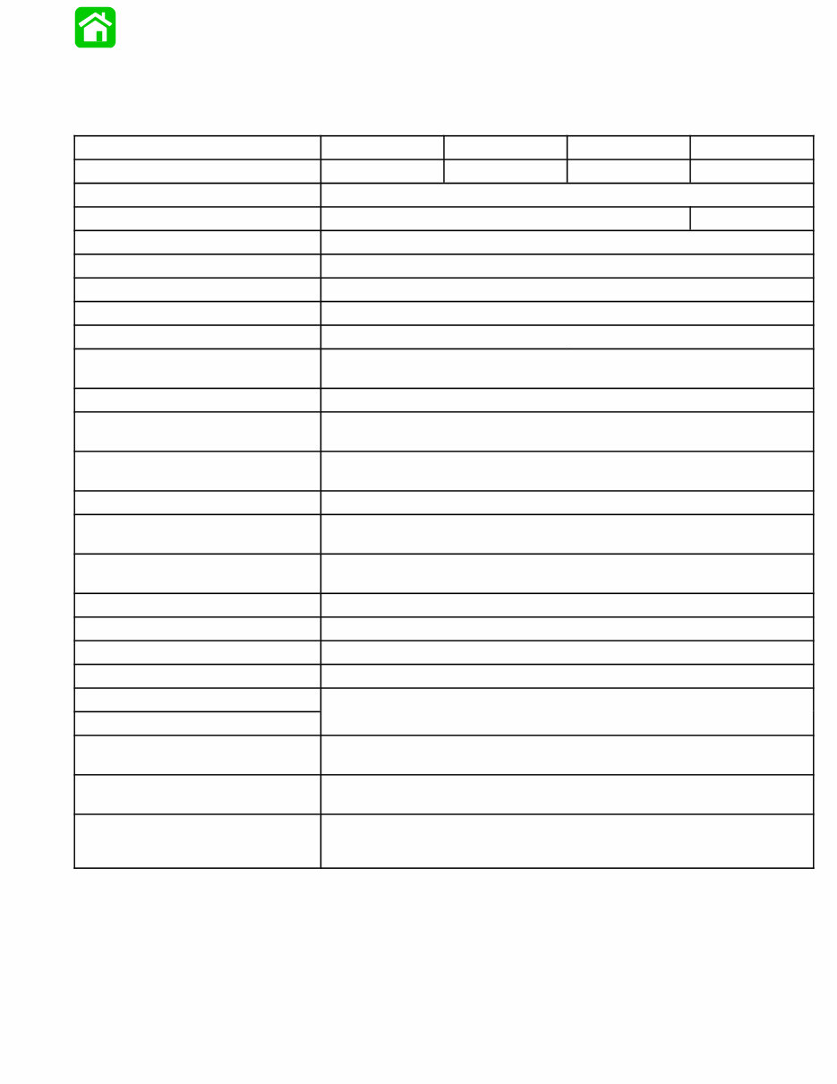
Model 70 Model 75 Model 80 Model 90
Horsepower 70 (52.2 kw) 75 (55.9 kw) 80 (59.6 kw) 90 (67.1 kw)
Idle RPM (in forward gear) 650 - 700
Full Throttle RPM Range 4750 - 5250 5000 - 5500
Piston Replacement 71.12 (1165.7cc)
Cylinder Bore 3.375 (85.7mm)
Stroke 2.65 (67.3mm)
Engine Type 3 Cylinder, 2 Cycle
Ignition Type C.D. Breakerless
Recommended Spark Plug
NGK-BUHW-2 or AC-V40 FFK or
Champion L78V
Inductor Plugs: NGK-BUZHW-2 or
Champion QL78V
Cylinder Firing Order 1-3-2
Recommended Power Trim Fluid
Quicksilver Power Trim & Steering Fluid or Automotive Transmission
Fluid (ATF) Type F, FA or Dexron II
Recommended Gasoline
Regular Leaded, Premium, Low-Lead and Lead-Free automotive gaso-
lines with a minimum pump posted octane rating of 86
Recommended Oil Quicksilver TC-WII or TC-W3 2-Cycle Outboard Oil
Engine Weight ELO
ELOPT
260 lbs.
280 lbs.
Fuel Tank Capacity
6.6 U.S. Gallons
(5 Imp. Gals.; 25 Liters)
Gear Housing Lubricant Capacity 22.5 fl. oz. (665.3ml)
Gasoline/Oil Ratio at Idle 80:1
Gasoline/Oil Ratio at W.O.T. 50:1
Gear Ratio 2.3:1
Oil Injection Tank Capacity
Tank Capacity 1 gal. (3.78 liter)
Maximum operation per tank
full of oil at W.O.T.
6 hours
Oil remaining when warning
buzzer sounds
1 qt. (.95 liter)
Operating time remaining at
wide open throttle when warn-
ing buzzer sounds
1 Hour
1-2 90-13645--2 1095 GENERAL INFORMATION AND SPECIFICATIONS
General Specification
(continued)
NOTE: Other specification (torques, etc.) are listed in
the respective sections.
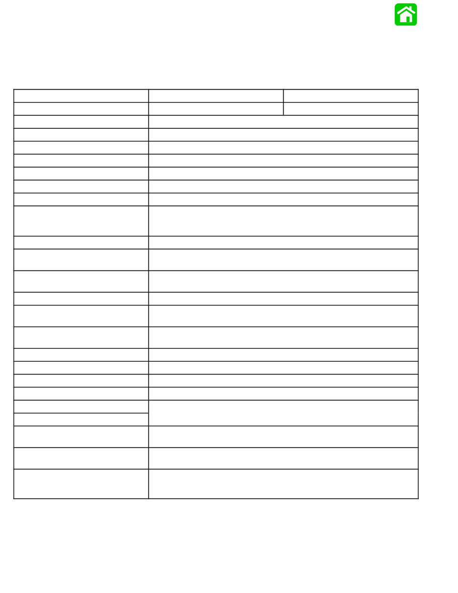
Model 100 Model 115
Horsepower 100 (74.6 kw) 115 (85.8 kw)
Idle RPM (in forward gear) 650 - 700
Full Throttle RPM Range 4750 - 5250
Piston Replacement 105 (1720.9cc)
Cylinder Bore 3.375 (85.7mm)
Stroke 2.930 (74.4mm)
Engine Type 4 Cylinder, 2 Cycle
Ignition Type C.D. Breakerless
Recommended Spark Plug
NGK-BPH8H-N-10* Gap - 0.040 in. (1.0mm)
Inductor Plug NGK BPZ 8H-N-10* Gap - 0.040 in. (1.0mm)
NGK-BUHW
Cylinder Firing Order 1-3-2-4
Recommended Power Trim Fluid
Quicksilver Power Trim & Steering Fluid or Automotive Transmission
Fluid (ATF) Type F, FA or Dexron II
Recommended Gasoline
Regular Leaded, Premium, Low-Lead and Lead-Free automotive gaso-
lines with a minimum pump posted octane rating of 86
Recommended Oil Quicksilver 2-Cycle Outboard Oil
Engine Weight ELO
ELOPT
340 lbs.
360 lbs.
Fuel Tank Capacity
6.6 U.S. Gallons
(5 Imp. Gals.; 25 Liters)
Gear Housing Lubricant Capacity 22.5 fl. oz. (665.2ml)
Gasoline/Oil Ratio at Idle 80:1
Gasoline/Oil Ratio at W.O.T. 50:1
Gear Ratio 2.07:1
Oil Injection Tank Capacity
Tank Capacity 1.4 gal. (5.3 liters)
Maximum operation per tank
full of oil at W.O.T.
5 hours
Oil remaining when warning
buzzer sounds
1 qt. (.95 liter)
Operating time remaining at
wide open throttle when warn-
ing buzzer sounds
50 min. approx.
*Improves running quality between 1800 – 2000 RPM.
90-13645--2 495 1-3 GENERAL INFORMATION AND SPECIFICATIONS
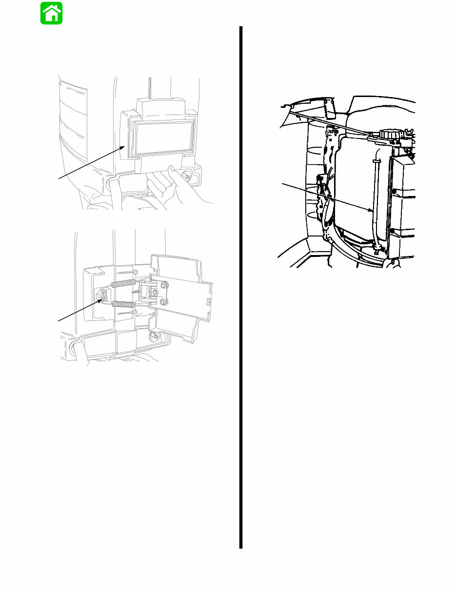
Cowl Removal
Pull outward on starboard side of front shield (a).
Remove spring (b) from latch and open cowls.
18291
a
18292
b
Filling Oil Injection System
Open starboard cowl (refer to cowl removal on this
page). Some earlier outboards will have a cowl brack-
et to hold cowl open as shown.
Fill tank with recommended oil.
a
a - Oil Tank Tube
You're Reading a Preview
What's Included?
Fast Download Speeds
Offline Viewing
Access Contents & Bookmarks
Full Search Facility
Print one or all pages of your manual
$31.99
1987-1993 Mercury Mariner 90HP 3-Cylinder Outboard OEM Service & Repair Manual
Viewed 14 Times Today

What's Included?
Fast Download Speeds
Offline Viewing
Access Contents & Bookmarks
Full Search Facility
Print one or all pages of your manual
$31.99

Secure transaction
What's Included?
Fast Download Speeds
Offline Viewing
Access Contents & Bookmarks
Full Search Facility
Print one or all pages of your manual
Description
This OEM Service & Repair Manual is tailored for repairing the 1987-1993 Mercury Mariner 90HP 3-Cylinder Outboard. It is a valuable tool for both professional mechanics and DIY enthusiasts, offering detailed, OEM-specific repair procedures and technical insights.
- Instant access without shipping costs
- Comprehensive guide covering repair procedures and technical diagnostics
- Printable pages for ease of use during repairs
- Designed for execution on Windows, Mac, and Linux systems
Whether you are a professional mechanic or a DIY enthusiast, this manual provides the precise information needed to initiate and complete repair processes efficiently for your Mercury Mariner.


