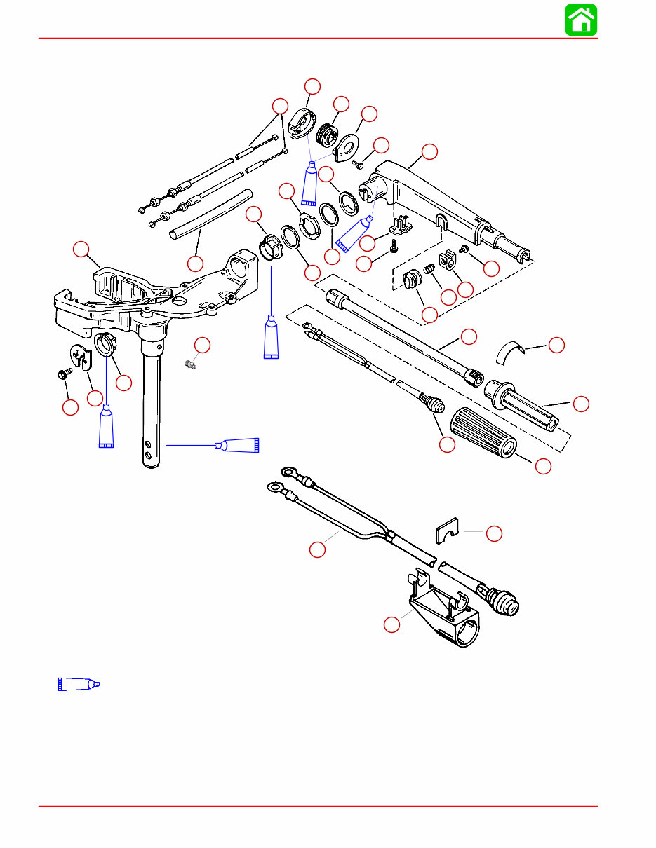
TILLER HANDLE 90-827242R1 MAY 1998 Page 7C-3 Swivel Head and Steering Handle REF. TORQUE REF . NO. QTY. DESCRIPTION lb. in. lb. ft. N·m 1 1 SWIVEL HEAD (BLACK) 2 2 BUSHING 3 1 PLATE 4 1 GREASE FITTING 5 2 SCREW (M5 x 1 x 16) 70 7.9 6 2 WASHER 7 1 WAVE WASHER 8 1 WASHER 9 1 STEERING HANDLE ARM (BLACK) 10 1 RETAINER 11 1 SCREW (M5 x .8 x 16) 35 4.0 12 1 COVER KIT 13 1 PULLEY 14 1 PULLEY CASE 15 1 SCREW (10-16 x 1/2) 20 2.3 16 2 THROTTLE CABLE 17 1 SLEEVE 18 1 DECAL 19 1 GRIP 20 1 STOP SWITCH 21 1 THROTTLE FRICTION KNOB Finger Tight 22 1 THROTTLE FRICTION LOCK As Required 23 1 SCREW (M6 x 1 x 25) 24 1 THROTTLE HANDLE 25 1 TILLER TUBE 26 1 SPRING 27 1 START/STOP SWITCH 28 1 HOUSING ELECTRIC HANDLE 29 1 CLIP
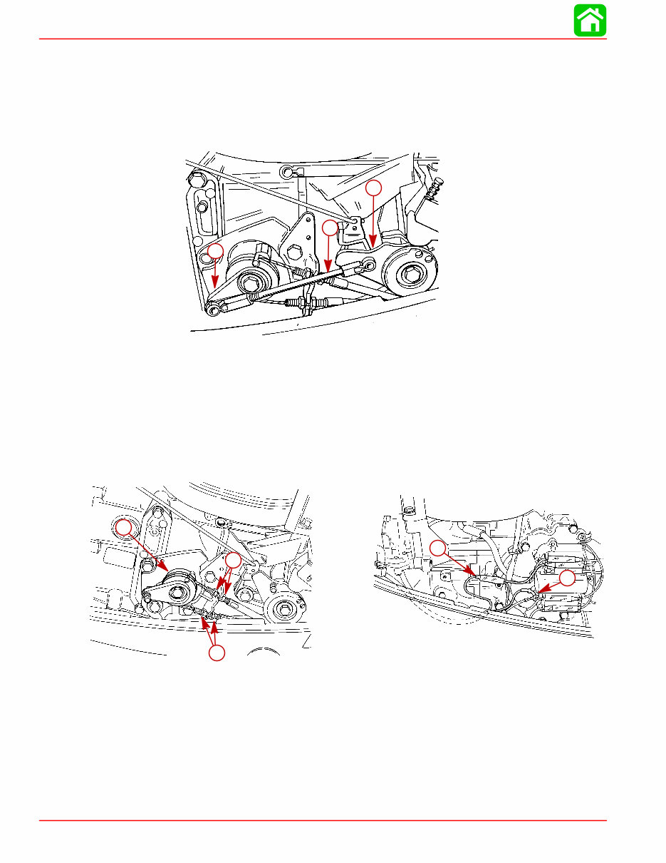
TILLER HANDLE Page 7C-4 90-827242R1 MAY 1998 Control Cables (Tiller Handle Shift Models) Removal 1. Place tiller handle twist grip in NEUTRAL position 2. Remove throttle link rod from throttle cam and primary throttle lever. 53046 a b c a b c a- Link Rod b- Throttle Cam c- Primary Throttle Lever 3. Loosen jam nuts which secure control cables to anchor bracket. 4. Unwrap and remove control cables from pulley of secondary gear. NOTE: If not replacing control cables, mark top cable with a piece of tape to aid in reassemb- ly. 5. Disconnect stop button wires – BLACK/YELLOW and BLACK. 53157 c 53162 a a b a a b d c a- Jam Nuts b- Secondary Gear c- BLACK/YELLOW d- BLACK
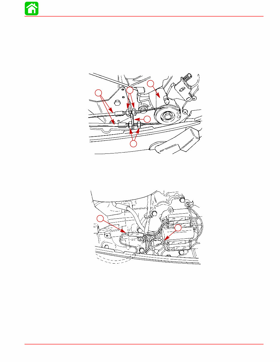
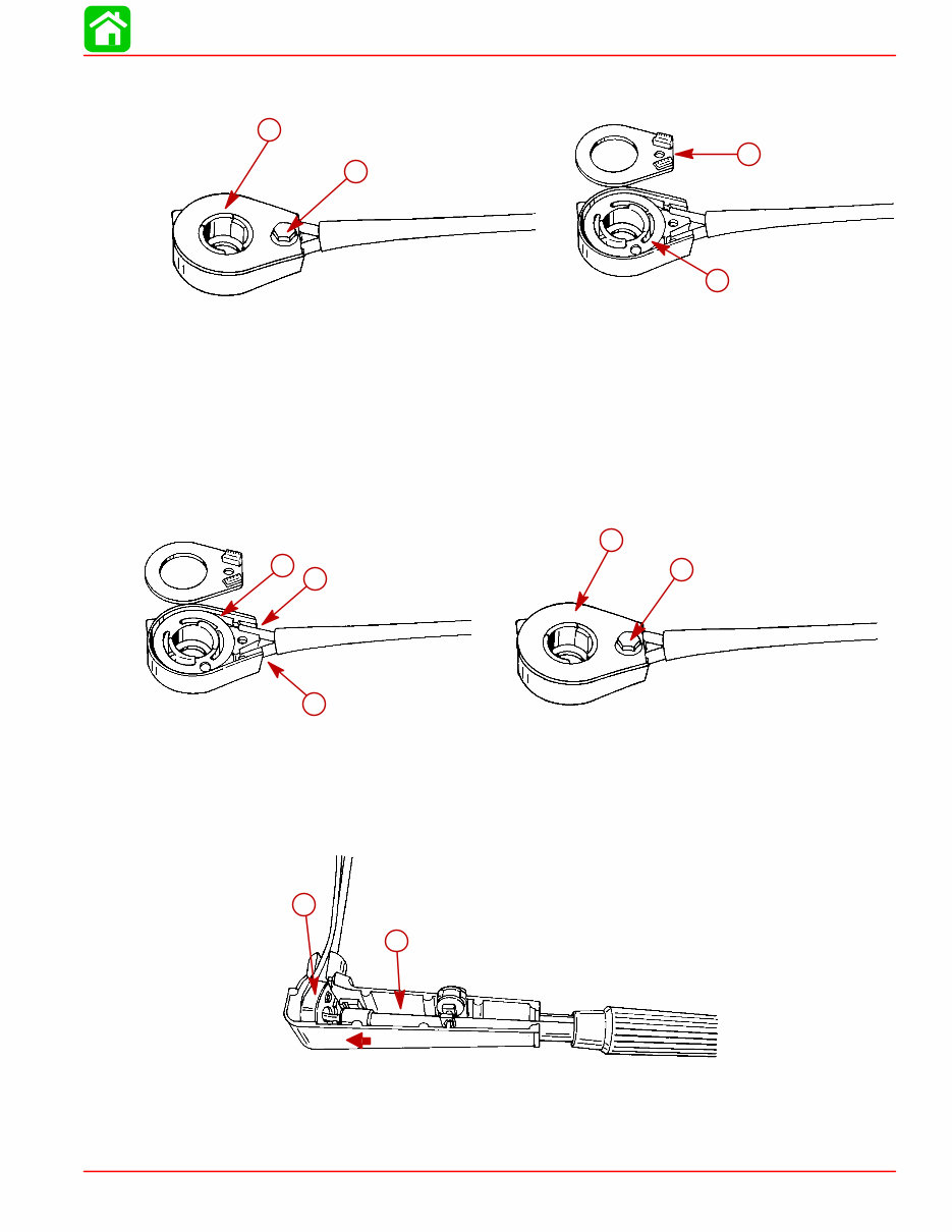
TILLER HANDLE 90-827242R1 MAY 1998 Page 7C-5 Throttle Cables (Side Shift Models) Removal 1. Loosen jam nuts which secure throttle cables to anchor bracket and remove cables from pulley of throttle cam. NOTE: If not replacing throttle cables, mark top cable with a piece of tape to aid in reassemb- ly. 53186 a b d c a c a b c a d a- Jam Nuts b- Throttle Cables c- Anchor Bracket d- Throttle Cam 2. Disconnect stop button wires – BLACK/YELLOW and BLACK. 53156 a b a b a- BLACK/YELLOW b- BLACK
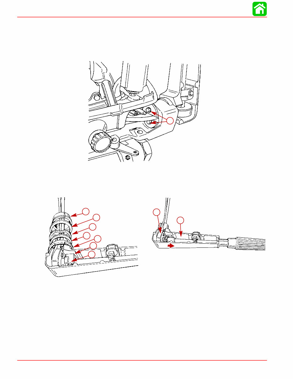
TILLER HANDLE Page 7C-6 90-827242R1 MAY 1998 Tiller Handle Removal/Disassembly Removal 1. Remove 2 bolts securing tiller handle to anchor bracket and remove tiller handle assem- bly. 53155 a a a- Bolts 2. Remove bushing, flatwashers (2). wave washer and tiller handle washer. Remove re- tainer and bolt. 3. Slide tiller tube out of pulley case. 53256 h g 53248 a b c b d e f g h a- Bushing b- Flat Washer (2) c- Wave Washer d- Tiller Handle Washer e- Retainer f- Bolt g- Tiller Tube h- Pulley Case
TILLER HANDLE 90-827242R1 MAY 1998 Page 7C-7 4. Remove pulley case assembly from tiller handle and remove cover bolt. 5. Remove cover and lift pulley assembly from case. Replace cables as required. 53257 c d 53262 a b a b c d a- Pulley Case Assembly b- Cover Bolt c- Cover d- Pulley Assembly Installation 1. Wrap cables around pulley. Top cable wraps and locks in top groove. Bottom cable wraps and locks in bottom groove. 2. Place pulley and cable assembly into pulley case. 3. Install pulley cover and secure cover with bolt. Torque bolt to 20 lb. in. (2.3 N·m). 53262 d e 53257 a b c a b c d e a- Pulley b- Top Cable c- Bottom Cable d- Cover e- Bolt [Torque to 20 lb. in. (2.3 N·m)] 4. Install pulley assembly into tiller handle and slide tiller tube into pulley. 53256 b a a b a- Pulley Assembly b- Tiller Tube
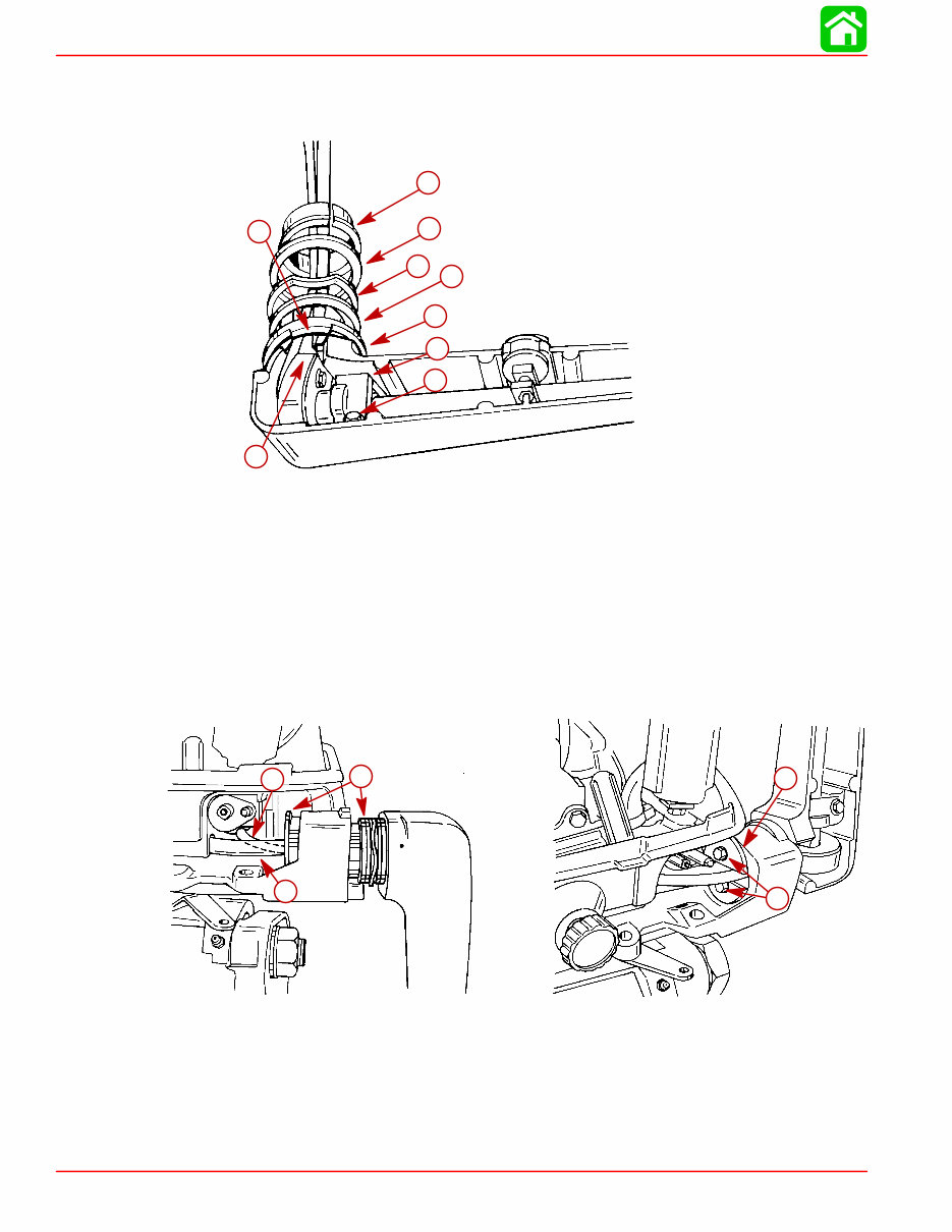
TILLER HANDLE Page 7C-8 90-827242R1 MAY 1998 5. Secure tiller tube in handle with retainer and bolt. Torque bolt to 35 lb. in. (4.0 N·m). 6. Install tiller washer (tab aligns with slot in handle), plain washer, wave washer, plain washer and flanged bushing over cable/harness assembly. 53248 d e d e h f g f c a b a- Retainer b- Bolt [Torque to 35 lb. in. (4.0 N·m)] c- Tiller washer d- Tab e- Slot f- Plain Washer g- Wave Washer h- Flanged Bushing 7. Slide tiller handle assembly into anchor bracket. 8. Route stop button harness through fuel connector opening in bottom cowl. 9. Route control cables through opening in bottom cowl. 10. Align tabs of inner and outer flanged bushings with slots in anchor bracket. 11. Pull on cable ends to remove slack and secure tiller handle to anchor bracket with plate and 2 bolts. Torque bolts to 70 lb. in. (7.9 N·m). 53155 d e 53169 c a b a b c d e a- Stop Button Harness b- Control Cables c- Tabs d- Plate e- Bolts [Torque to 70 lb. in. (7.9 N·m)]
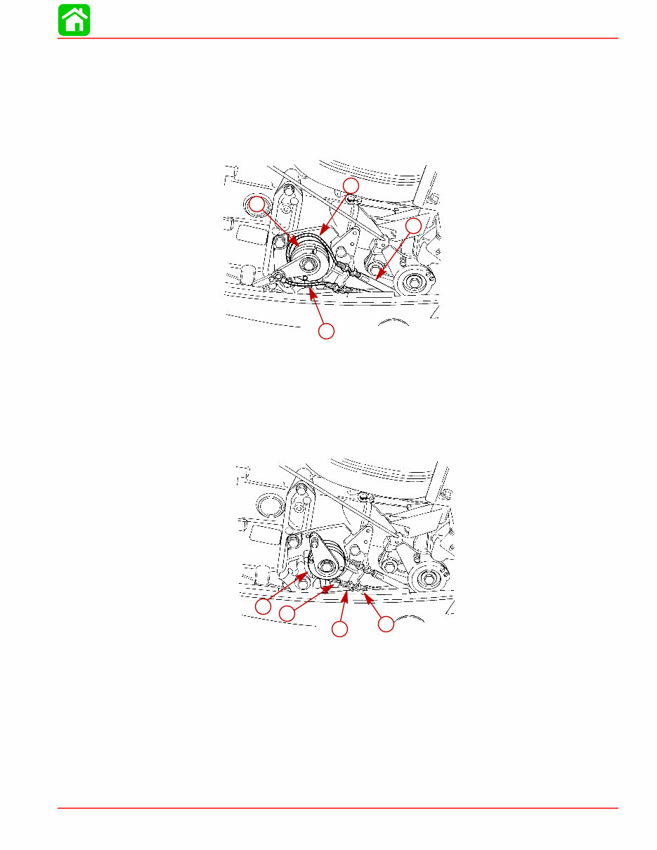
TILLER HANDLE 90-827242R1 MAY 1998 Page 7C-9 Control Cables (Tiller Handle Shift Models) Installation 1. Rotate tiller handle twist grip to REVERSE gear position. 2. Route extended cable over top of secondary gear pulley and secure cable into inner groove of pulley. Place cable jacket into inner notch of cable anchor bracket. 53164 b a c d a b c d a- Extended Cable b- Inner Groove c- Cable Jacket d- Inner Notch 3. Rotate tiller handle to FORWARD gear position. 4. Route remaining cable below secondary gear pulley and secure cable into outer groove of pulley. Place cable jacket into lower notch of cable anchor bracket. 53165 c d a b a b c d a- Cable b- Outer Groove c- Cable Jacket d- Lower Notch
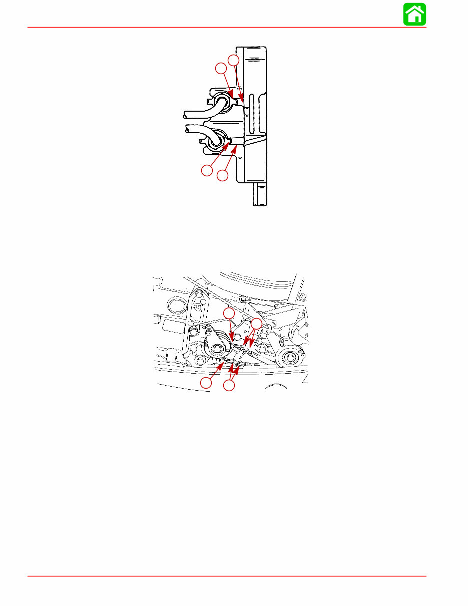
TILLER HANDLE Page 7C-10 90-827242R1 MAY 1998 5. Position tab washers to lock control cables to holes of cable anchor bracket. a b b a a- Tab Washers b- Hole 6. Rotate tiller handle twist grip to NEUTRAL. 7. Adjust jam nuts to remove slack from control cables while allowing full travel of throttle/ shift linkage. 53165 b b a a a a b b a- Jam Nuts b- Cables 8. After cables are adjusted, verify FORWARD, NEUTRAL and REVERSE gears can be selected while smoothly advancing and retarding throttle. If throttle/shift operation is not correct, inspect for pinched or kinked cables, misaligned linkage or loose attaching bolts. NOTE: It may be necessary to rotate propeller shaft in order to select REVERSE gear.
Upon purchasing this manual, you will receive a .PDF file containing an email contact. After contacting us, you will receive a reply with a link to access the manual for your Mercury 9.9 HP 2 Stroke 2002.
This comprehensive manual covers every aspect of your machine, providing detailed guidance for tasks ranging from an oil change to a transmission swap. With hundreds of pages, it includes numerous illustrations and easy-to-understand text to assist you. The manual also features a search function, allowing you to easily navigate and print necessary pages.
Designed as a Factory Service Repair Manual, it offers step-by-step instructions for maintenance and repair, equipping owners with the knowledge typically possessed by factory-trained technicians. By utilizing the insights within this manual, owners can confidently make informed decisions about maintaining and repairing their machine.
Our commitment extends beyond delivering a high-quality service manual; we also provide exceptional customer service, ensuring your satisfaction.
Recently Viewed
5,521,897Happy Clients
2,594,462eManuals
1,120,453Trusted Sellers
15Years in Business
Price:
Actual Price:
2002 Mercury 9.9 HP 2 Stroke Service & Repair Manual