

1998-2005 Mercury Mariner 75HP 2-Stroke Outboard OEM Service & Repair Manual
What's Included?
Fast Download Speeds
Online & Offline Access
Access PDF Contents & Bookmarks
Full Search Facility
Print one or all pages of your manual

Quick Reference Data
VEHICLE HISTORY DATA
MODEL: YEAR:
VIN NUMBER:
ENGINE SERIAL NUMBER:
CARBURETOR SERIAL NUMBER OR I.D. MARK:
Record the numbers here for your reference.
MAINTENANCE SCHEDULE
Maintenance interval Maintenance required
Before each use Check the lanyard switch operation*
Inspect the propeller for damage
Check the propeller nut tightness
Inspect the fuel system for leakage
Check the outboard mounting bolt tighteness
Check the steering for binding or looseness
Check the shift and throttle control
After each use Flush the cooling system
Wash debris from the gearcase
After the first 10 days of operation Check the gearcase lubricant level
Every 30 day or 50 hours of usage Check the gearcase lubricant level
IX
(continued)

MAINTENANCE SCHEDULE (continued)
Maintenance interval Maintenance required
Once a season or 100 hours of usage Lubricate the steering system
Lubricate tiller control pivots*
Lubricate the tilt and swivel shaft
Lubricate the shift and throttle linkages/cables
Check the tightness of all accessible fasteners
Clean and inspect the spark plugs
Remove carbon from the combustion chambers
Inspect fuel filters for contamination
Check control cable adjustments
Adjust the carburetors*
Test and inspect the battery
Check ignition timing
Check trim/tilt fluid level (Chapter Eleven)
Clean and inspect sacrificial anodes
Lubricate the drive shaft splines
Lubricate the propeller shaft splines
Change the gearcase lubricant
Lubricate the starter motor pinion
Clean remote fuel tank filter*
Change the water separating filter (EFI)*
Inspect or replace the water pump impeller
Replace the compressor air filter (Optimax)*
Clean the compressor cooling water strainer*
Before long term storage Drain and refill the gearcase lubricant
*This maintenance item does not apply to all models.
LUBRICANT CAPACITIES
Model Oil capacity Gearcase capacity
65 jet, 75 hp and 90 hp 1 gal. (3.8 liter)* 22.5 oz. (665 ml)*
80 jet and 100-125 hp
(except 115 Optimax) 1.4 gal (5.3 liter)* 22.5 oz. (665 ml)*
105 jet and 140 jet 12.9 qt. (12.2 liter) –
135-200 hp (except Optimax) 12.9 qt. (12.2 liter)* 22.5 oz. (665 ml)*
115-175 hp Optimax models 13.5 qt. (12.8 liter)* 22.5 oz. (665 ml)*
200/225 hp Optimax, 225 hp and 250 hp 13.5 qt. (12.8 liter) 28.0 oz. (828 ml)*
*Approximate capacity. Always add lubricant until it reaches the full level.
SPARK PLUG RECOMMENDATIONS
Model Recommended plug Spark plug gap
65 jet, 75 hp and 90 hp NGK BUHW-2 Surface gap plug
Alternate plug (resistor type) NGK BUZHW-2 Surface gap plug
80 jet, 100 hp, 115 hp and 125 hp NGK BP8H-N-10 0.040 in. (1.0 mm)
Alternate plug (resistor type) NGK-BPZ8H-N-10 0.040 in. (1.0 mm)
105 jet and 140 jet
1998 and 1999 NGK BU8H Surface gap plug
2000-on NGK BPZ8HS-10 0.040 in. (1.0 mm)
135-200 hp (except Optimax)
1998 and 1999 NGK BU8H surface gap plug
2000-on NGK BPZ8HS-10 0.040 in. (1.0 mm)
X
(continued)

SPARK PLUG RECOMMENDATIONS (continued)
Model Recommended plug Spark plug gap
115-150 hp (Optimax models) NGK PZFR5F-11 0.040 in. (1.0 mm)
Alternate plug NGK ZFR5F-11 0.040 in. (1.0 mm)
Alternate plug Champion RC12MC4 0.040 in. (1.0 mm)
200 and 225 hp (Optimax models)
1998 and 1999 NGK PZFR5F-11 0.040 in. (1.0 mm)
Alternate plug NGK ZFR5F-11 0.040 in. (1.0 mm)
2000 Champion QC12GMC 0.040 in. (1.0 mm)
2001-on NGK PZFR5F-11 0.040 in. (1.0 mm)
225 and 250 hp (except Optimax) Champion QL77CC 0.035 in. (0.9 mm)
BATTERY CAPACITY
Provides continuous Approximate
Accessory draw power for: recharge time
80 amp-hour battery
5 amps 13.5 hours 16 hours
15 amps 3.5 hours 13 hours
25 amps 1.6 hours 12 hours
105 amp-hour battery
5 amps 15.8 hours 16 hours
15 amps 4.2 hours 13 hours
25 amps 2.4 hours 12 hours
STANDARD TORQUE SPECIFICATIONS
Screw or nut size in.-lb. ft.-lb. N•m
U.S. Standard
6-32 9 – 1.0
8-32 20 – 2.3
10-24 30 – 3.4
10-32 35 – 4.0
12-24 45 – 5.1
1/4-20 70 – 7.9
1/4-28 84 – 9.5
5/16-18 160 13 18.1
5/16-24 168 14 19.0
3/8-16 – 23 31.1
3/8-24 – 25 33.8
7/16-14 – 36 48.8
7/16-20 – 40 54.2
1/2-13 – 50 67.8
1/2-20 – 60 81.3
Metric
M5 36 – 4.1
M6 70 – 8.1
M8 156 13 17.6
M10 – 26 35.3
M12 – 35 47.5
M14 – 60 81.3
XI

Chapter One
General Information
This detailed, comprehensive manual contains com-
plete information on maintenance and overhaul. Hun-
dreds of photos and drawings guide the reader through
every step-by-step procedure.
Troubleshooting, tune-up, maintenance and repair pro-
cedures are not difficult with the necessary tools and equip-
ment, and the ability to use them. Anyone with some
mechanical ability can perform most of the procedures in
this manual. See Chapter Two for more information on
tools and techniques.
A shop manual is a reference. Clymer books are de-
signed for finding information quickly. All chapters are
thumb tabbed and important topics are indexed at the end
of the manual. All procedures, tables, photos and instruc-
tions in this manual assume the reader may be working on
the machine or using the manual for the first time.
Store the manual with other tools in the workshop or
boat. It will help in gaining a better understanding of how
the boat runs, and help to lower repair and maintenance
costs.
MANUAL ORGANIZATION
Chapter One provides general information useful to
boat owners and mechanics.
Chapter Two discusses the tools and techniques for pre-
ventative maintenance, troubleshooting and repair.
Chapter Three provides troubleshooting procedures for
all engine systems and individual components.
Chapter Four provides maintenance, lubrication and
tune-up instructions.
Additional chapters cover storage, adjustment and spe-
cific repair instructions. All disassembly, inspection and
assembly instructions are in step-by-step form. Specifica-
tions are included at the end of the appropriate chapters.
WARNINGS, CAUTIONS AND NOTES
The terms, WARNING, CAUTION and NOTE have
specific meanings in this manual.
1

A WARNING emphasizes areas where injury or even
death could result from negligence. Mechanical damage
may also occur. WARNINGS are to be taken seriously .
A CAUTION emphasizes areas where equipment dam-
age could occur. Disregarding a CAUTION could cause
permanent mechanical damage, though injury is unlikely.
A NOTE provides additional information to make a step
or procedure easier or clearer. Disregarding a NOTE
could cause inconvenience, but would not cause equip-
ment damage or personal injury.
TORQUE SPECIFICATIONS
Torque specifications throughout this manual are given
in foot-pounds (ft.-lb.), inch-pounds (in.-lb.) and newton
meters (N•m). Torque wrenches calibrated in me-
ter-kilograms can be used by performing a simple conver-
sion: move the decimal point one place to the right. For
example, 4.7 mkg = 47 N•m. This conversion is accurate
enough for mechanical repairs even though the exact
mathematical conversion is 3.5 mkg = 34.3 N•m.
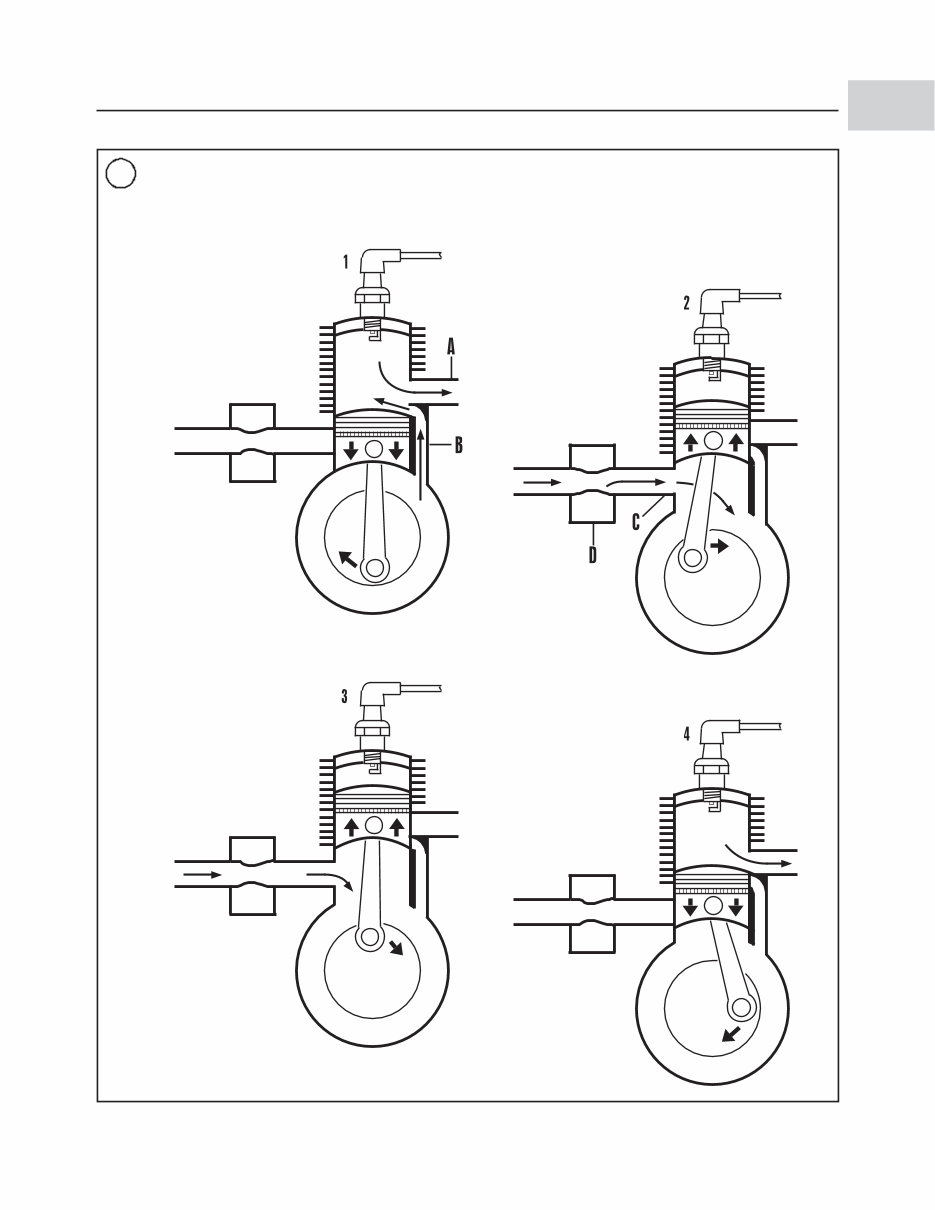
ENGINE OPERATION
All marine engines, whether two- or four-stroke, gaso-
line or diesel, operate on the Otto cycle of intake, compres-
sion, power and exhaust phases. A two-stroke engine
requires one crankshaft revolution (two strokes of the pis-
ton) to complete the Otto cycle. All Mercury and Mariner
engines covered in this manual are of the two-stroke de-
sign. Figure 1 shows typical gasoline two-stroke engine
operation.
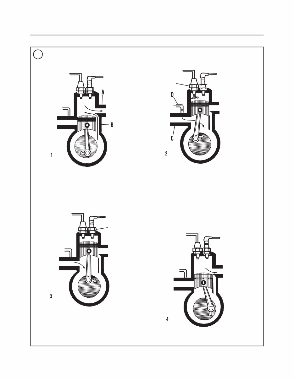
Optimax models use a direct fuel injection system. On
these models, fuel is injected directly into the combustion
chamber after the exhaust port is covered; preventing un-
burned fuel from exiting along with the exhaust gases.
Compared to typical two-stroke engines, direct fuel in-
jected engines run smoother, emit far less unburned fuel,
use less oil and provide improved fuel economy. Figure 2
shows direct injection two-stroke engine operation.
FASTENERS
The material and design of the various fasteners used on
marine equipment are specifically chosen for perfor-
mance and safety. Fastener design determines the type of
tool required to work with the fastener. Fastener material
is carefully selected to decrease the possibility of physical
failure or corrosion. See Galvanic Corrosion in this chap-
ter for information on marine materials.
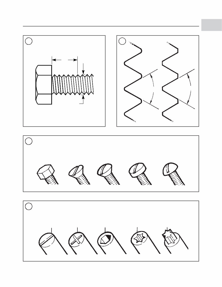
Threaded Fasteners
Nuts, bolts and screws are manufactured in a wide
range of thread patterns. To join a nut and bolt, the diame-
ter of the bolt and the diameter of the hole in the nut must
be the same. The threads must also be compatible.
Determine if the threads on the fasteners are compatible
by turning the nut on the bolt (or bolt into its respective
opening) with fingers only. Make sure both pieces are
clean. If much force is required, check the thread condi-
tion on each fastener. If the thread condition is good but
the fasteners jam, the threads are not compatible.
Four important specifications describe the thread:
1. Diameter.
2. Threads per inch.
3. Thread pattern.
4. Thread direction.
Figure 3 shows the first two specifications. Thread pat-
tern is more subtle. Italian and British standards exist, but
the most commonly used by marine equipment manufac-
turers are American and metric. The root and top of the
thread are cut differently as shown in Figure 4.
Most threads are cut so the fastener must be turned
clockwise to tighten it. These are called right-hand
threads. Some fasteners have left-hand threads; they must
be turned counterclockwise for tightening. Left-hand
threads are used in locations where normal rotation of the
equipment would loosen a right-hand threaded fastener.
Fasteners with left-hand threads are identified in the in-
structions.
Machine Screws
There are many different types of machine screws (Fig-
ure 5). Most are designed to protrude above the secured
surface (rounded head) or be slightly recessed below the
surface (flat head). In some applications, the screw head is
recessed well below the fastened surface. Figure 6 shows
a number of screw heads requiring different types of turn-
ing tools. See Chapter Two for detailed information.
Bolts
Commonly called bolts, the technical name for these
fasteners is cap screw. They are normally described by di-
ameter, threads per inch and length. For example, 1/4-20 ×
1 indicates a bolt that is 1/4 in. in diameter with 20 threads
per inch, and is 1 in. long. The measurement across two
flats on the head of the bolt indicates the proper wrench
size to use.
2 CHAPTER ONE
GENERAL INFORMATION 3
1
1
As the piston travels
downward, it uncovers the
exhaust port (A) allowing the
exhaust gases to leave the
cylinder. A fresh air-fuel
charge, which has been
compressed slightly in the
crankcase, enters the cylinder
through the transfer port (B).
Since this charge enters under
pressure, it also helps to push
out the exhaust gases.
As the piston travels down,
the exhaust gases leave the
cylinder and the complete
cycle starts all over again.
As the piston almost reaches
the top of the travel, the spark
plug fires, igniting the
compressed air-fuel mixture.
The piston continues to top
dead center (TDC) and is
pushed downward by the
expanding gases.
While the crankshaft
continues to rotate, the piston
moves upward, covering the
transfer (B) and exhaust (A)
ports. The piston compresses
the new air-fuel mixture and
creates a low-pressure area in
the crankcase at the same
time. As the piston continues
to travel, it uncovers the
intake port (C). A fresh air-fuel
charge from the carburetor (D)
is drawn into the crankcase
Spark
plug
TWO-STROKE OPERATING PRINCIPLES
(EXCEPT OPTIMAX MODELS)
4 CHAPTER ONE
2
TWO-STROKE OPERATING PRINCIPLES
OPTIMAX MODELS (DIRECT INJECTION)
As the piston travels downward, it uncovers the exhaust
port (A) allowing the exhaust gases to leave the cylinder.
A fresh air-oil charge, which has been compressed
slightly in the crankcase, enters the cylinder through the
transfer port (B). Since this charge enters under
pressure, it also helps to push out the exhaust gases.
As the piston travels down, the exhaust gases leave the
cylinder and the complete cycle starts all over again.
As the piston almost reaches the top of its travel, the
spark plug fires, igniting the compressed air-fuel
mixture. The piston continues to top dead center (TDC)
and is pushed downward by the expanding gases.
While the crankshaft continues to rotate, the piston
moves upward, covering the transfer (B) and exhaust
ports (A). The piston compresses the fresh air charge
and creates a low-pressure area in the crankcase. A
computer controlled electronic pump delivers a precise
amount of oil into the crankcase through a dedicated
passage (D). The fresh air-oil charge is drawn into the
crankcase through the intake opening (C). Further
upward movement of the piston closes the transfer port
(B) and exhaust port (A). After both ports close, the
computer controlled direct injector sprays the required
amount of fuel into the combustion chamber.
Spark plug
Direct injector
GENERAL INFORMATION 5
1
3 4
1.in.
(TPI)
Diameter
American Metric
60°
60°
5
MACHINE SCREWS
Flat Hex Oval Filister Round
6
OPENINGS FOR TURNING TOOLS
Slotted Phillips Allen Internal torx External torx
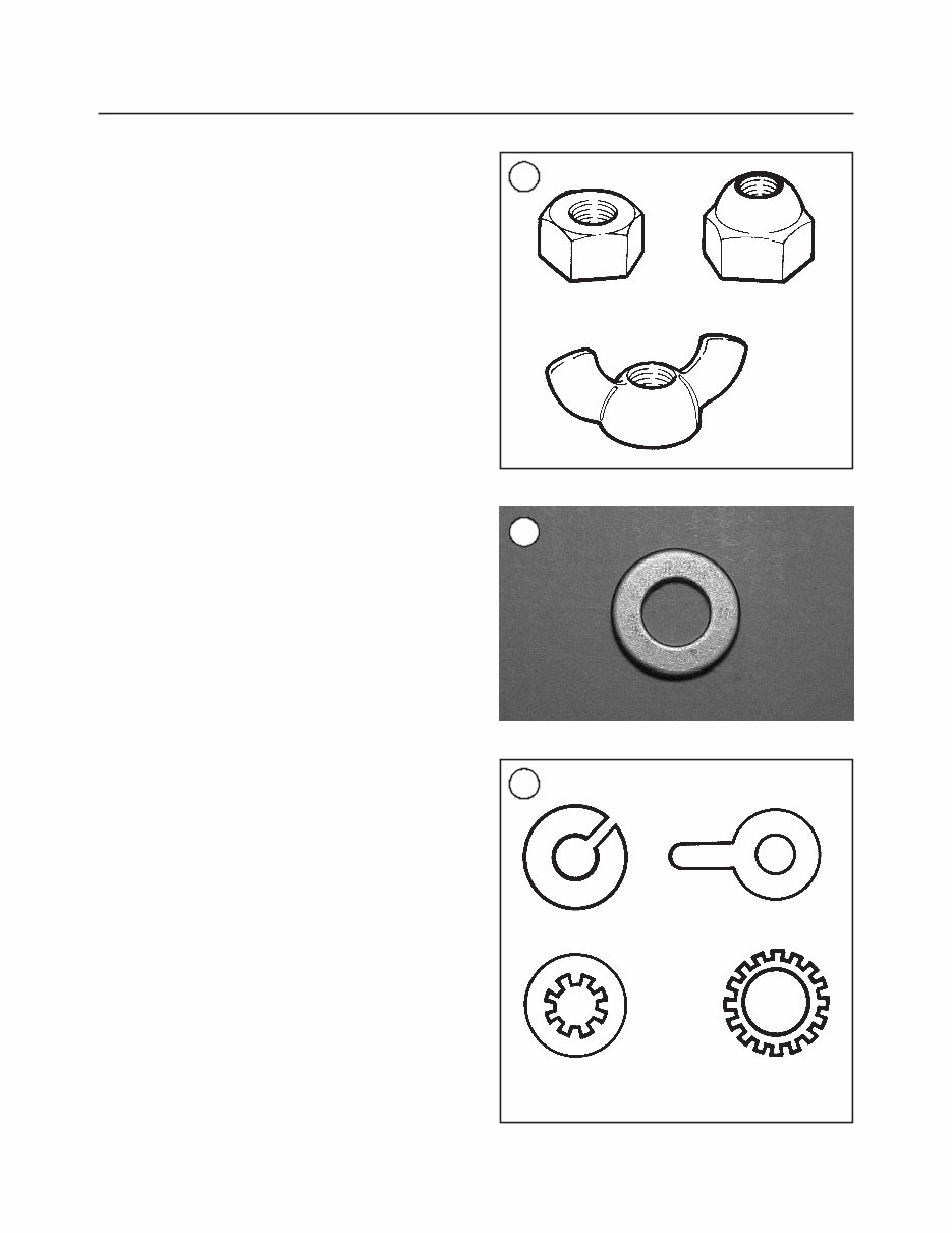
Nuts
Nuts are manufactured in a variety of types and sizes.
Most are hexagonal (six-sided) and fit on bolts, screws
and studs with the same diameter and threads per inch.
Figure 7 shows several types of nuts. The common nut
is usually used with some type of lockwasher.
Self-locking nuts have a nylon insert that helps prevent
the nut from loosening; no lockwasher is required. Wing
nuts are designed for fast removal by hand. Wing nuts are
used for convenience in non-critical locations.
To indicate the size of a nut, manufacturers specify the
diameter of the opening and the threads per inch. This is
similar to a bolt specification, but without the length di-
mension. The measurement across two flats on the nut in-
dicates the wrench size to use.
Washers
There are two basic types of washers: flat washers and
lockwashers. Flat washers (Figure 8) are simple discs
with a hole that fits the screw or bolt. Lockwashers are de-
signed to prevent a fastener from working loose due to vi-
bration, expansion and contraction. Figure 9 shows
several types of lockwashers. Flat washers are often used
between a lockwasher and a fastener to provide a smooth
bearing surface. This allows the fastener to be turned eas-
ily with a tool.
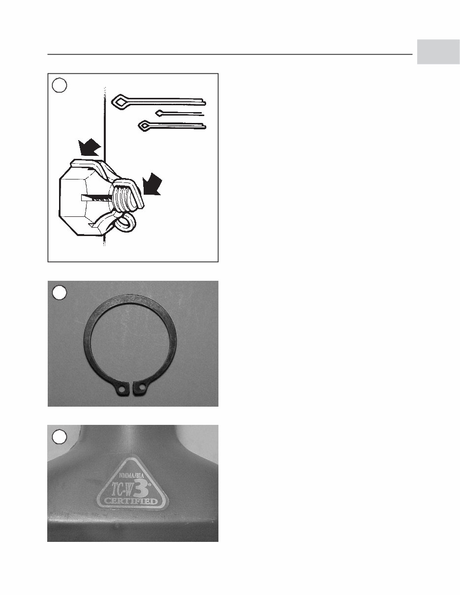
Cotter Pins
Cotter pins (Figure 10) are used to secure special kinds
of fasteners. The threaded stud, bolt or shaft has a hole for
the cotter pin; the nut or nut lock piece has projections for
the cotter pin. This type of nut is called a castellated nut.
Always replace the cotter pin if it is removed.
Snap Rings
Snap rings (Figure 11) can be an internal or external de-
sign. They are used to retain components on shafts (exter-
nal type) or within openings (internal type). Snap rings
can be reused if they are not distorted during removal. In
some applications, snap rings of varying thickness can be
selected to position or control end play of parts assem-
blies.
LUBRICANTS
Periodic lubrication ensures long service life for any
type of equipment. It is especially important with marine
6 CHAPTER ONE
7
Common nut
Self-locking nut
Wing nut
8
9
Internal tooth
Plain
Folding
External tooth
equipment because of exposure to salt, brackish or pol-
luted water and other harsh environments. The type of lu-
bricant used is just as important as the lubrication service
itself; although, in an emergency, the wrong type of lubri-
cant is better than none at all. The following sections de-
scribe the types of lubricants most often used on marine
equipment. Follow the equipment manufacturer’s recom-
mendations for the lubricant types.
Generally, all liquid lubricants are called oil. They may
be mineral-based (including petroleum bases), natu-
ral-based (vegetable and animal bases), synthetic-based
or emulsions (mixtures). Grease is an oil thickened with
additives, and maybe enhanced with anticorrosion, anti-
oxidant and extreme pressure (EP) additives. Grease is of-
ten classified by the type of thickener added; lithium and
calcium soap are the most commonly used.
Two-stroke Engine Oil
Lubrication for a two-stroke engine is provided by oil
mixed into the incoming air or air-fuel mixture. Some of
the oil mist settles in the crankcase, lubricating the crank-
shaft, bearings and lower end of the connecting rod. The
rest of the oil enters the combustion chamber to lubricate
the piston, rings and the cylinder wall. This oil is then
burned with the air-fuel mixture during the combustion
process.
Engine oil must have several special qualities to work
well in a two-stroke engine. It must mix easily and stay in
suspension with gasoline. When burned, it cannot leave
behind excessive deposits. It must also withstand the high
operating temperatures associated with two-stroke en-
gines.
The National Marine Manufacturer’s Association
(NMMA) has set standards for oil used in two-stroke, wa-
ter-cooled engines (TC-W). This is the NMMA TC-W
grade (Figure 12). It indicates the oil’s performance in the
following areas:
1. Lubrication (prevention of wear and scuffing).
2. Spark plug fouling.
3. Piston ring sticking.
4. Preignition.
5. Piston varnish.
6. General engine condition (including deposits).
7. Exhaust port blockage.
8. Rust prevention.
9. Mixing ability with gasoline.
In addition to oil grade, manufacturers specify the ratio
of gasoline to oil required during break-in and normal en-
gine operation.
GENERAL INFORMATION 7
1
10
Correct installation
of cotter pin
11
12
You're Reading a Preview
What's Included?
Fast Download Speeds
Online & Offline Access
Access PDF Contents & Bookmarks
Full Search Facility
Print one or all pages of your manual
$39.99
Viewed 91 Times Today


Secure transaction
What's Included?
Fast Download Speeds
Online & Offline Access
Access PDF Contents & Bookmarks
Full Search Facility
Print one or all pages of your manual
$39.99
- The 1998-2005 Mercury Mariner 75HP 2-Stroke Outboard Service & Repair Manual is a comprehensive resource for fixing outboard problems, providing troubleshooting and replacement procedures recommended by the manufacturer.
- It includes step-by-step instructions, clear images, and exploded-view illustrations, making it useful for both professional mechanics and DIY enthusiasts.
- Regular maintenance is essential for outboard longevity, and this manual offers the manufacturer's recommended troubleshooting charts and replacement procedures to ensure proper maintenance.
- Having this manual on hand can help save on repairs, increase outboard reliability, and prevent issues, making it a valuable resource for outboard owners.
- This is not a generic repair manual but the OEM manual used by professional technicians, ensuring accuracy and reliability.
- It eliminates the hassle of searching through numerous pages and offers the convenience of digital access, allowing easy searching, bookmarking, and even printing if desired.
- It is printable and available in English, compatible with various electronic devices including PC, Mac, Android, and Apple devices, requiring only Adobe Reader (free) for access.


