Mercury Mariner 6 HP 4-stroke Factory Service Repair Manual
What's Included?
Lifetime Access
Fast Download Speeds
Online & Offline Access
Access PDF Contents & Bookmarks
Full Search Facility
Print one or all pages of your manual
MODELS SERVICE MANUAL Mercury/Mariner 4 ⋅ 5 ⋅ 6 (4-Stroke) 0R000001 and Above Starting Serial Numbers Printed in U.S.A. 2000, Mercury Marine 90-857138R1 MAY 2000
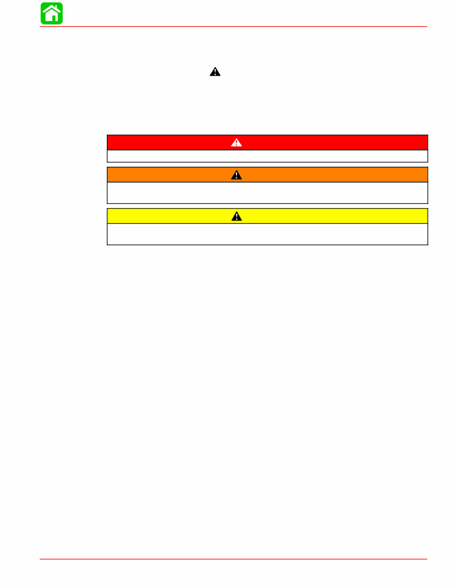
90-857138R1 MAY 2000 Page i Notice Throughout this publication, “Dangers”, “Warnings” and “Cautions” (accompanied by the In- ternational HAZARD Symbol ) are used to alert the mechanic to special instructions con- cerning a particular service or operation that may be hazardous if performed incorrectly or carelessly. OBSERVE THEM CAREFULLY! These “Safety Alerts” alone cannot eliminate the hazards that they signal. Strict compliance to these special instructions when performing the service, plus “Common Sense” operation, are major accident prevention measures. DANGER DANGER - Immediate hazards which WILL result in severe personal injury or death. WARNING WARNING - Hazards or unsafe practices which COULD result in severe personal in- jury or death. CAUTION Hazards or unsafe practices which could result in minor personal injury or product or property damage. Notice to Users of This Manual This service manual has been written and published by the Service Department of Mercury Marine to aid our dealers’ mechanics and company service personnel when servicing the products described herein. It is assumed that these personnel are familiar with the servicing procedures of these prod- ucts, or like or similar products manufactured and marketed by Mercury Marine, that they have been trained in the recommended servicing procedures of these products which in- cludes the use of mechanics’ common hand tools and the special Mercury Marine or recom- mended tools from other suppliers. We could not possibly know of and advise the service trade of all conceivable procedures by which a service might be performed and of the possible hazards and/or results of each method. We have not undertaken any such wide evaluation. Therefore, anyone who uses a service procedure and/or tool, which is not recommended by the manufacturer, first must completely satisfy himself that neither his nor the products safety will be endangered by the service procedure selected. All information, illustrations and specifications contained in this manual are based on the latest product information available at the time of publication. As required, revisions to this manual will be sent to all dealers contracted by us to sell and/or service these products. It should be kept in mind, while working on the product, that the electrical system and ignition system are capable of violent and damaging short circuits or severe electrical shocks. When performing any work where electrical terminals could possibly be grounded or touched by the mechanic, the battery cables should be disconnected at the battery. Any time the intake or exhaust openings are exposed during service they should be covered to protect against accidental entrance of foreign material which could enter the cylinders and cause extensive internal damage when the engine is started.
Page ii 90-857138R1 MAY 2000 It is important to note, during any maintenance procedure replacement fasteners must have the same measurements and strength as those removed. Numbers on the heads of the met- ric bolts and on the surfaces of metric nuts indicate their strength. American bolts use radial lines for this purpose, while most American nuts do not have strength markings. Mis- matched or incorrect fasteners can result in damage or malfunction, or possibly personal injury. Therefore, fasteners removed should be saved for reuse in the same locations when- ever possible. Where the fasteners are not satisfactory for re-use, care should be taken to select a replacement that matches the original. Cleanliness and Care of Outboard Motor A marine power product is a combination of many machined, honed, polished and lapped surfaces with tolerances that are measured in the ten thousands of an inch/mm. When any product component is serviced, care and cleanliness are important. Throughout this manu- al, it should be understood that proper cleaning, and protection of machined surfaces and friction areas is a part of the repair procedure. This is considered standard shop practice even if not specifically stated. Whenever components are removed for service, they should be retained in order. At the time of installation, they should be installed in the same locations and with the same mating surfaces as when removed. Personnel should not work on or under an outboard which is suspended. Outboards should be attached to work stands, or lowered to ground as soon as possible. We reserve the right to make changes to this manual without prior notification. Refer to dealer service bulletins for other pertinent information concerning the products de- scribed in this manual. Page Numbering Two number groups appear at the bottom of each page. The example below is self-explana- tory. EXAMPLE: 90-826883 R1 JANUARY 1998 Page - 6A-7 Revision No. 1 Month of Printing Year of Printing Section Number Part of Section Letter Page Number
1 2 3 4 5 6 7 8 Important Information Electrical Fuel System Powerhead Mid-Section Lower Unit Attachment/Control Linkage Manual Starter 9 Color Diagrams 90-857138R1 MAY 2000 Page iii Service Manual Outline Section 1 - Important Information A - Specifications B - Maintenance C - General Information D - Outboard Installation Section 2 - Electrical A - Ignition B - Charging & Starting System C - Timing, Synchronizing & Adjusting D - Wiring Diagrams Section 3 - Fuel System A - Fuel Pump B - Carburetor C - Emissions Section 4 - Powerhead A - Cylinder Head B - Cylinder Block/Crankcase Section 5 - Mid-Section A - Clamp/Swivel Brackets & Drive Shaft Housing Section 6 - Lower Unit Section 7 - Attachments/Control Linkage A - Shift Linkage B - Tiller Handle Section 8 - Manual Starter Section 9 - Color Diagrams
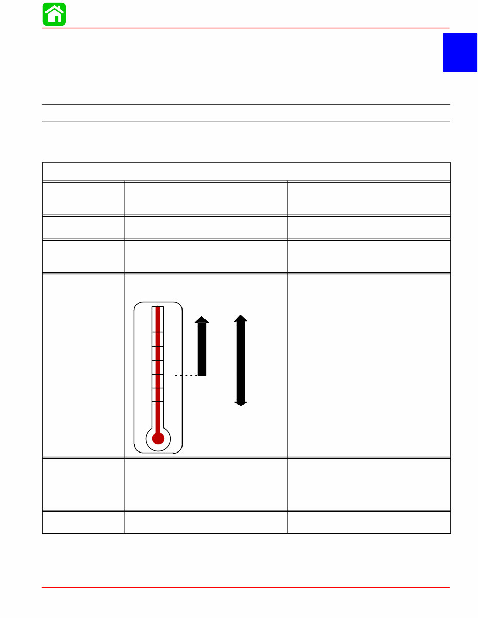
1 A SPECIFICATIONS 90-857138R1 MAY 2000 Page 1A-1 IMPORTANT INFORMATION Section 1A - Specifications Table of Contents Specifications 1A-1 . . . . . . . . . . . . . . . . . . . . . . . . . . . Propeller Information Charts 1A-8 . . . . . . . . . . . . . . Specifications Model 4/5/6 (4-Stroke) HORSEPOWER (kW) Model 4 Model 5 Model 6 4 hp (2.9 kW) 5 hp (3.7 kW) 6 hp (4.4 kW) OUTBOARD WEIGHT Short Shaft Long Shaft 55 lbs. (25.0 kg) 57 lbs. (26.0 kg) FUEL RECOMMENDED GASOLINE Automotive Unleaded with a Minimum Pump Posted Octane Rating of 87 OIL ENGINE OIL CAPACITY ENGINE OIL +20 +40 +60 +80 F° C° 0 +100 –7 +4 +16 +27 –18 +38 SAE 10W-30 SAE 25W-40 Either 15 fl oz. or 450 ml. SAE 10W-30 viscosity oil is recom- mended for use in all temperatures. SAE 25W-40 viscosity oil may be used at temperatures above 40° F (4° C). Use Quicksilver 4-Cycle Marine Oil with the proper viscosity for the expected temperature in your area (see range thermometer on left). If not available, use a premium quality 4-cycle engine oil, cer- tified to meet or exceed anyone of the following American Petroleum Institute (API) service classifications SH, SG, SF, CF-4, CE, CD, CDll. CHARGING SYSTEM Readings taken @ 68°F (20°C). Alternator (Optional) Type: Lighting Coil Lighting Coil Resistance Battery Charging Rectifier (Optional) 12 Volt 60 Watt (Non Regulated Lighting Coil) 0.31 - 0.47 Ω (YEL/RED - YEL/RED) 2 Amperes (Rectified) STARTING SYSTEM Manual Start Recoil Starter
SPECIFICATIONS 90-857138R1 MAY 2000 Page 1A-3 FUEL SYSTEM Fuel Pump Type Fuel Pump: Pressure Plunger Stroke Diaphragm Stroke Fuel Tank Capacity External (Plunger/Diaphragm) 2.5 - 5.0 psi (17 - 35 kPa) 0.059 in. (1.5 mm) 0.059 in. (1.5 mm) 3.2 US Gallons CYLINDER BLOCK Type Displacement Number of Cylinders 4 Stroke Cycle – Over Head Valve 7.5 cu. in. (123 cc) 1 STROKE Length 1.77 in. (45 mm) CYLINDER BORE Diameter Standard Oversize-0.020 in. (0.50 mm) Taper/Out of Round Maximum Bore Type 2.323 in. (59.00 mm) 2.343 in. (59.50 mm) 0.003 in. (0.076 mm) Steel PISTON Piston Type O.D. at Skirt Standard Oversize-0.020 in. (0.50 mm) Aluminum 2.321 in. (58.960 mm) 2.341 in. (59.460 mm) PISTON CLEARANCE Piston to Cylinder Clearance Piston Clearance Limit 0.001 - 0.002 in. (0.020 - 0.055 mm) 0.006 in. (0.15 mm) RINGS Ring End Gap (Installed) Top Middle Bottom (Oil Ring) Side Clearance: Top Middle Bottom (Oil Ring) 0.006 - 0.014 in. (0.15 - 0.35 mm) 0.012 - 0.020 in. (0.30 - 0.50 mm) 0.008 - 0.016 in. (0.20 - 0.40 mm) 0.0015 - 0.003 in. (0.04 - 0.08 mm) 0.0012 - 0.003 in. (0.03 - 0.07 mm) 0.0004 - 0.007 in. (0.01 - 0.18 mm) COMPRESSION RATIO Compression Ratio With Decompression 4/5 (1999 & 2000) 4/5 (2001 & Newer) 6 (2000 & Newer) 8.5:1 42 psi ± 14 psi (0.29 ± 0.1 MPa) 9.5:1 42 psi ± 14 psi (0.29 ± 0.1 MPa) PISTON PIN Outer Diameter Diameter of Piston Pin Hole Clearance between Piston Pin and Piston Pin Hole 0.6299 in. (16.00 mm) 0.6300 in. (16.002 mm) 0.0001 - 0.0005 in. (0.002 mm - 0.012 mm) CONNECTING ROD Oil Clearance (Big End) Side Clearance (Big End) Small End Inside Diameter 0.002 - 0.003 in. (0.053 - 0.079 mm) 0.008 - 0.016 in. (0.20 - 0.40 mm) 0.6303 in. (16.01 mm)
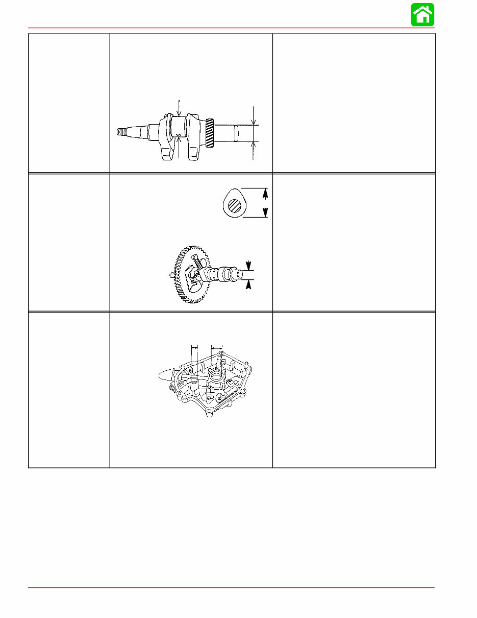
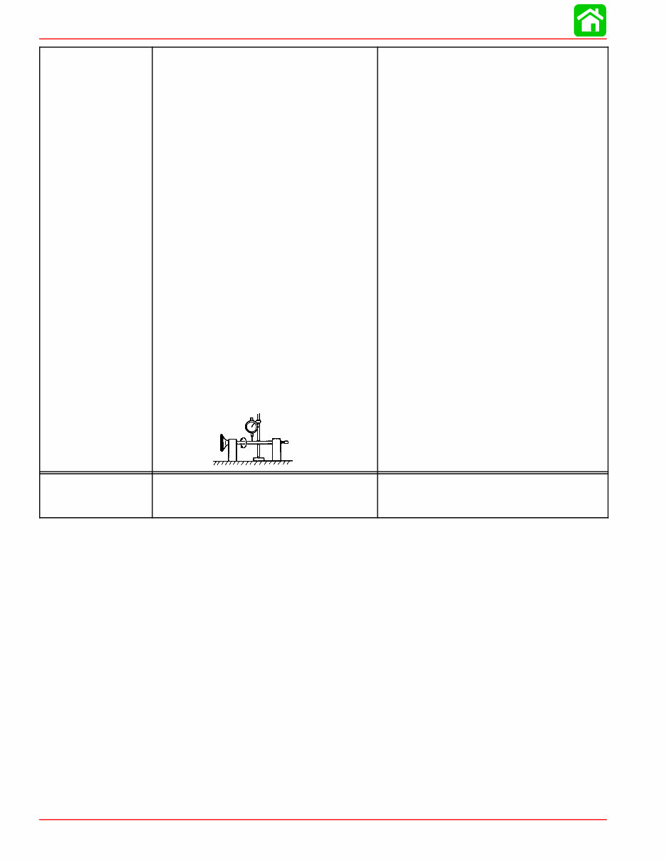
SPECIFICATIONS Page 1A-4 90-857138R1 MAY 2000 CRANKSHAFT Crankshaft Runout Diameter of Crank Pin (A) Outer Diameter of Crankshaft in Oil Pan Bearing (B) A B Less than 0.002 in. (0.05 mm) 1.179 - 1.177 in. (29.94 - 29.91 mm) 0.983 - 0.982 in. (24.98 - 24.96 mm) CAMSHAFT Camshaft Dimensions Intake/Exhaust “A” 4 (1999 & 2000) 5 (1999 & 2000) 6 (2000) 4/5/6 (2001 & Newer) Bearing Diameter “B” A B 0.993 in. (25.24 mm) 1.047 in. (26.59 mm) 1.115 in. (28.33 mm) 1.115 in. (28.33 mm) 0.550 in. (13.98 mm) OIL PAN Inside Diameter of Oil Pan Bearing: Crankshaft “A” Camshaft “B” Crankshaft to Oil Pan Bearing Clearance Camshaft to Oil Pan Bearing Clearance A B 0.985 in. (25.01 mm) 0.5515 in. (14.01 mm) 0.0006 - 0.0015 in. (0.015 - 0.040 mm) 0.0008 - 0.002 in. (0.02 - 0.05 mm)
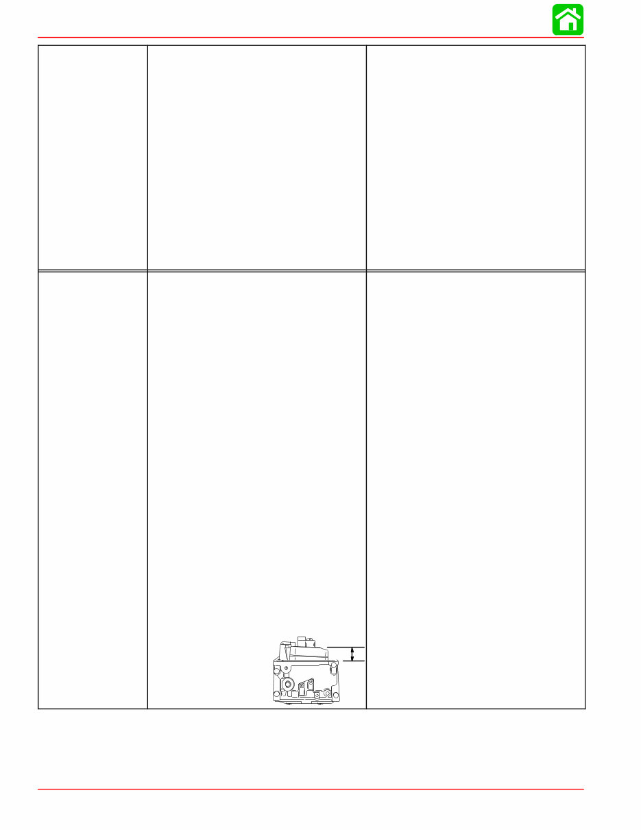
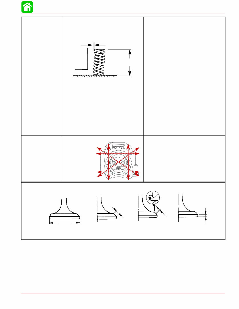
SPECIFICATIONS 90-857138R1 MAY 2000 Page 1A-5 VALVE SPRING Free Length (Intake/Exhaust) “a” Tilt Limit “b” (Intake/Exhaust) 4/5 (1999) 4/5/6 (2000 & Newer) Compressed Pressure (Installed) Intake/Exhaust: Closed Height 0.965 in. (24.4 mm) 4/5 (1999 & 2000) 6 (2000) 4/5/6 (2001 & Newer) Open Height 0.709 in. (17.4 mm) 4/5 (1999 & 2000) 6 (2000) 4/5/6 (2001 & Newer) Direction of Winding (Intake/Exhaust) a b a = 1.260 in. (32.0 mm) b = 0.044 in. (1.12 mm) a = 1.378 in. (35.0 mm) b = 0.044 in. (1.12 mm) 17 lbf. (7.7 kgf) 24 lbf. (10.8 kgf) 24 lbf. (10.8 kgf) 31 lbf. (14.0 kgf) 39.4 lbf. (17.9 kgf) 39.4 lbf. (17.9 kgf) Right Hand CYLINDER HEAD Warp Limit * * Lines indicate straight edge measurement 0.0012 in. (0.03 mm) “A” “B” “C” “D” Valve Dimensions Head Diameter Face Width Seat Width Margin Thickness
SPECIFICATIONS Page 1A-6 90-857138R1 MAY 2000 VALVES Valve/Valve Seat/Valve Guides: Valve Clearance (cold) Intake Exhaust Valve Dimensions: “A” Head Diameter Intake Exhaust “B” Face Width Intake Exhaust “C” Seat Width Intake Exhaust “D” Margin Thickness Intake Exhaust Stem Outside Diameter Intake Exhaust Guide Inside Diameter Intake Exhaust Stem To Guide Clearance Intake Exhaust Stem Run-out Limit (max.) 0.002 - 0.005 in. (0.06 - 0.14 mm) 0.004 - 0.007 in. (0.11 - 0.19 mm) 0.980 - 0.988 in. (24.9 - 25.1 mm) 0.941 - 0.949 in. (23.9 - 24.1 mm) 0.102 in. (2.6 mm) 0.102 in. (2.6 mm) 0.031 in. (0.8 mm) 0.031 in. (0.8 mm) 0.028 in. (0.7 mm) 0.047 in. (1.2 mm) 0.216 in. (5.48 mm) 0.214 in. (5.44 mm) 0.2165 in. (5.5 mm) 0.2165 in. (5.5 mm) 0.0008 - 0.0017 in. (0.020 - 0.044 mm) 0.0018 - 0.0028 in. (0.045 - 0.072 mm) 0.0006 in. (0.016 mm) THERMOSTAT Valve Opening Temperature Full Open Temperature Valve Lift (Minimum) 122°F - 129°F (50°C - 54°C) 145°F - 153°F (63°C - 67°C) 0.12 in. (3 mm)
The Mercury Mariner 6 HP 4-stroke Factory Service Repair Manual is a comprehensive resource for repairing and adjusting your Mercury Mariner 6 HP 4-stroke engine. It is designed to be a valuable reference for both professional mechanics and DIY enthusiasts. The manual covers detailed explanations of installation, removal, disassembly, assembly, repair, and check procedures, presented in a sequential order.
Serial Numbers: 0R000001 and Above
This manual is known by various names:
Mercury Mariner 6 HP 4-stroke service manual
Mercury Mariner 6 HP 4-stroke repair manual
Mercury Mariner 6 HP 4-stroke workshop manual
Mercury Mariner 6 HP 4-stroke shop manual
All the above manuals are one and the same.
Upon purchase, you will have immediate access to the manual, which is divided into chapters. The manual index provides an overview of the content:
Important information
Electrical
Fuel system
Powerhead
Mid-section
Lower unit
Attachment/control linkage
Manual starter
Color diagrams
Each chapter is further divided into sections, with each section containing sub-sections. The manual includes exploded diagrams at the beginning of each removal and disassembly section to aid in identifying parts and clarifying procedure steps. The manual is available in PDF format, allowing for easy printing of specific pages or the entire manual as needed.
Recently Viewed
5,521,897Happy Clients
2,594,462eManuals
1,120,453Trusted Sellers
15Years in Business
Price:
Actual Price:
Mercury Mariner 6 HP 4-stroke Factory Service Repair Manual