Mercury Mariner 50 HP 4-stroke Factory Service Repair Manual
What's Included?
Lifetime Access
Fast Download Speeds
Online & Offline Access
Access PDF Contents & Bookmarks
Full Search Facility
Print one or all pages of your manual
MODELS United States 0T178500 and Above . . . . . With Serial Numbers SERVICE MANUAL 50 S 60 (4-STROKE) 2001 AND NEWER Printed in U.S.A. 2000, Mercury Marine 90-858896 MAY 2000
90-858896 MAY 2000 Page i Notice Throughout this publication, “Dangers”, “Warnings” and “Cautions” (accompanied by the In- ternational HAZARD Symbol ) are used to alert the mechanic to special instructions con- cerning a particular service or operation that may be hazardous if performed incorrectly or carelessly. OBSERVE THEM CAREFULLY! These “Safety Alerts” alone cannot eliminate the hazards that they signal. Strict compliance to these special instructions when performing the service, plus “Common Sense” operation, are major accident prevention measures. DANGER DANGER - Immediate hazards which WILL result in severe personal injury or death. WARNING WARNING - Hazards or unsafe practices which COULD result in severe personal in- jury or death. CAUTION Hazards or unsafe practices which could result in minor personal injury or product or property damage. Notice to Users of This Manual This service manual has been written and published by the Service Department of Mercury Marine to aid our dealers’ mechanics and company service personnel when servicing the products described herein. It is assumed that these personnel are familiar with the servicing procedures of these prod- ucts, or like or similar products manufactured and marketed by Mercury Marine, that they have been trained in the recommended servicing procedures of these products which in- cludes the use of mechanics’ common hand tools and the special Mercury Marine or recom- mended tools from other suppliers. We could not possibly know of and advise the service trade of all conceivable procedures by which a service might be performed and of the possible hazards and/or results of each method. We have not undertaken any such wide evaluation. Therefore, anyone who uses a service procedure and/or tool, which is not recommended by the manufacturer, first must completely satisfy himself that neither his nor the products safety will be endangered by the service procedure selected. All information, illustrations and specifications contained in this manual are based on the latest product information available at the time of publication. As required, revisions to this manual will be sent to all dealers contracted by us to sell and/or service these products. It should be kept in mind, while working on the product, that the electrical system and ignition system are capable of violent and damaging short circuits or severe electrical shocks. When performing any work where electrical terminals could possibly be grounded or touched by the mechanic, the battery cables should be disconnected at the battery. Any time the intake or exhaust openings are exposed during service they should be covered to protect against accidental entrance of foreign material which could enter the cylinders and cause extensive internal damage when the engine is started.
Page ii 90-858896 MAY 2000 It is important to note, during any maintenance procedure replacement fasteners must have the same measurements and strength as those removed. Numbers on the heads of the met- ric bolts and on the surfaces of metric nuts indicate their strength. American bolts use radial lines for this purpose, while most American nuts do not have strength markings. Mis- matched or incorrect fasteners can result in damage or malfunction, or possibly personal injury. Therefore, fasteners removed should be saved for reuse in the same locations when- ever possible. Where the fasteners are not satisfactory for re-use, care should be taken to select a replacement that matches the original. Cleanliness and Care of Outboard Motor A marine power product is a combination of many machined, honed, polished and lapped surfaces with tolerances that are measured in the ten thousands of an inch/mm. When any product component is serviced, care and cleanliness are important. Throughout this manu- al, it should be understood that proper cleaning, and protection of machined surfaces and friction areas is a part of the repair procedure. This is considered standard shop practice even if not specifically stated. Whenever components are removed for service, they should be retained in order. At the time of installation, they should be installed in the same locations and with the same mating surfaces as when removed. Personnel should not work on or under an outboard which is suspended. Outboards should be attached to work stands, or lowered to ground as soon as possible. We reserve the right to make changes to this manual without prior notification. Refer to dealer service bulletins for other pertinent information concerning the products de- scribed in this manual. EXAMPLE: 90-826148R1 JANUARY 1996 LOWER UNIT - 6A-7 Revision No. 1 Month of Printing Year of Printing Section Description Section Number Part of Section Letter Page Number
1 2 3 4 5 6 7 9 Important Information Electrical Fuel System Powerhead Mid-Section Lower Unit Attachments/ Control Linkage 8 Color Diagrams 90-858896 MAY 2000 Page iii Service Manual Outline Section 1 - Important Information A - Specifications B - Maintenance C - General Information D - Outboard Motor Installation Section 2 - Electrical A - Ignition B - Charging & Starting System C - Timing,Synchronizing & Adjusting D - Wiring Diagrams Section 3 - Fuel System A - Fuel Pump B - Carburetor C - Emissions Section 4 - Powerhead A - Cylinder Head B - Cylinder Block/Crankcase C - Lubrication Section 5 - Mid-Section A - Clamp/Swivel Brackets & Drive Shaft Housing B - Power Trim C - Manual Tilt Assist Section 6 - Lower Unit A - Non-Bigfoot Gear Housing B - Bigfoot Gear Housing Section 7 - Attachments/Control Linkage A - Throttle/Shift Linkage B - Tiller Handle Section 8 - Color Diagrams
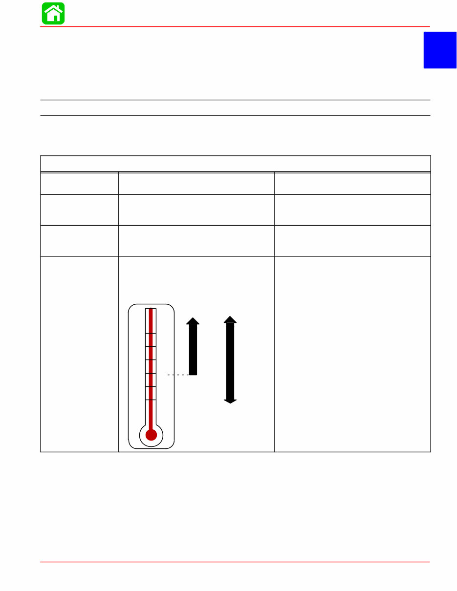
1 A SPECIFICATIONS 90-858896 MAY 2000 Page 1A-1 IMPORTANT INFORMATION Section 1A - Specifications Table of Contents Specifications 1A-1 . . . . . . . . . . . . . . . . . . . . . . . . . . . Propeller Information Charts 1A-8 . . . . . . . . . . . . . . Specifications Models 50/60 (4-Stroke) HORSEPOWER (kW) Model 50 Model 60 50 hp (37.7 Kw) @ 5750 rpm 60 hp (44.7 Kw) @ 5750 rpm OUTBOARD WEIGHT Electric 50/60 ELPT 50/60 ELPT BIGFOOT 236 lb (107.2 kg) 252 lb (114.2 kg) FUEL RECOMMENDED GASOLINE Automotive Unleaded with a Minimum Pump Posted Octane Rating of 87 OIL OIL FILTER OIL FILTER WRENCH ENGINE OIL CAPACITY ENGINE OIL +20 +40 +60 +80 F° C° 0 +100 –7 +4 +16 +27 –18 +38 SAE 10W-30 SAE 25W-40 p/n 35-822626A2 p/n 91-802653Q1 Either 3 Quarts or 3 Liters SAE 10W-30 viscosity oil is recom- mended for use in all temperatures. SAE 25W-40 viscosity oil may be used at temperatures above 40° F (4° C). Use Quicksilver 4-Cycle Marine Oil with the proper viscosity for the expected temperature in your area (see range thermometer on left). If not available, use a premium quality 4-cycle engine oil, cer- tified to meet or exceed anyone of the following American Petroleum Institute (API) service classifications SH, SG, SF, CF-4, CE, CD, CDll.
SPECIFICATIONS Page 1A-2 90-858896 MAY 2000 IGNITION SYSTEM Readings taken @ 68°F (20°C). Type Spark Plug: Type Gap Hex Size Torque Hole Size Firing Order Ignition Timing: @ Idle (Cold Start) @ Idle (800 rpm) @ WOT (6000 rpm) Charge Coil Resistance Crank Position Sensor Resistance Ignition Coil Resistance: Primary Secondary (W/o Boots) ECM Engine Speed Limiter Soft Reduction (Retards Timing) Spark Cut-Out Reduction (Percent- ages of ignition spark are Cut-Out) ECM Overheat/Low Oil Pressure Speed Control Engine Temperature Sensor Capacitor Discharge Ignition NGK DPR6EA-9 0.035 in. (1.0 mm) 18 mm 150 lb-in. (17 Nm) 12 mm 1-3-4-2 15° B.T.D.C 5° B.T.D.C 28° B.T.D.C 660 - 710 Ω (GRN/WHT - WHT/GRN) 300 - 350 Ω (RED - WHT) 0.08 - 0.7 Ω (BLK - BLK/WHT) 3.5 - 4.7 kΩ (BLK - High Tension) 6200 rpm 6250 rpm Approximately 2000 rpm See Graph Section 2A-Ignition CHARGING SYSTEM Readings taken @ 68°F (20°C). Alternator Type: 6 Amp. Manual Lighting Coil Output Lighting Coil Resistance 15 Amp. Electric Alternator Output Battery Charging Coil Resistance Power Bobbin Resistance (For Electrothermal Valve) Quicksilver Tachometer Setting Single Phase (12 Pole) 6 Amps. 0.9 - 1.1 Ohms (YEL-YEL) 12.6 V-15 Amps. (185 Watts) (Rectified/Regulated) 0.22 - 0.24 Ohms (YEL-YEL) 6.7-7.1 Ohms (YEL/BLK-YEL/BLK) “6P” or “4” STARTING SYSTEM Manual Start Electric Start: Starter Type Output Ampere Draw Under: (Load) (No Load) Recoil Starter Bendix 1.1 kW 174.0 Amps 23.7 Amps BATTERY Battery Rating Minimum Requirement For operation below 32° F (0° C) Ampere-Hours (Ah) Minimum For operation above 32° F (0° C) For operation below 32° F (0° C) 465 Marine Cranking Amps (MCA) or 350 Cold Cranking Amps (CCA) 1000 Marine Cranking Amps (MCA) or 775 Cold Cranking Amps (CCA) 70 105 ENRICHMENT CONTROL SYSTEM Readings taken @ 68°F (20°C). Auto Enrichener Resistance Electrothermal ram projection 15 - 25 Ohms (YEL/BLK - YEL/BLK) 0.3 in. (7 mm) after 5 min. of power
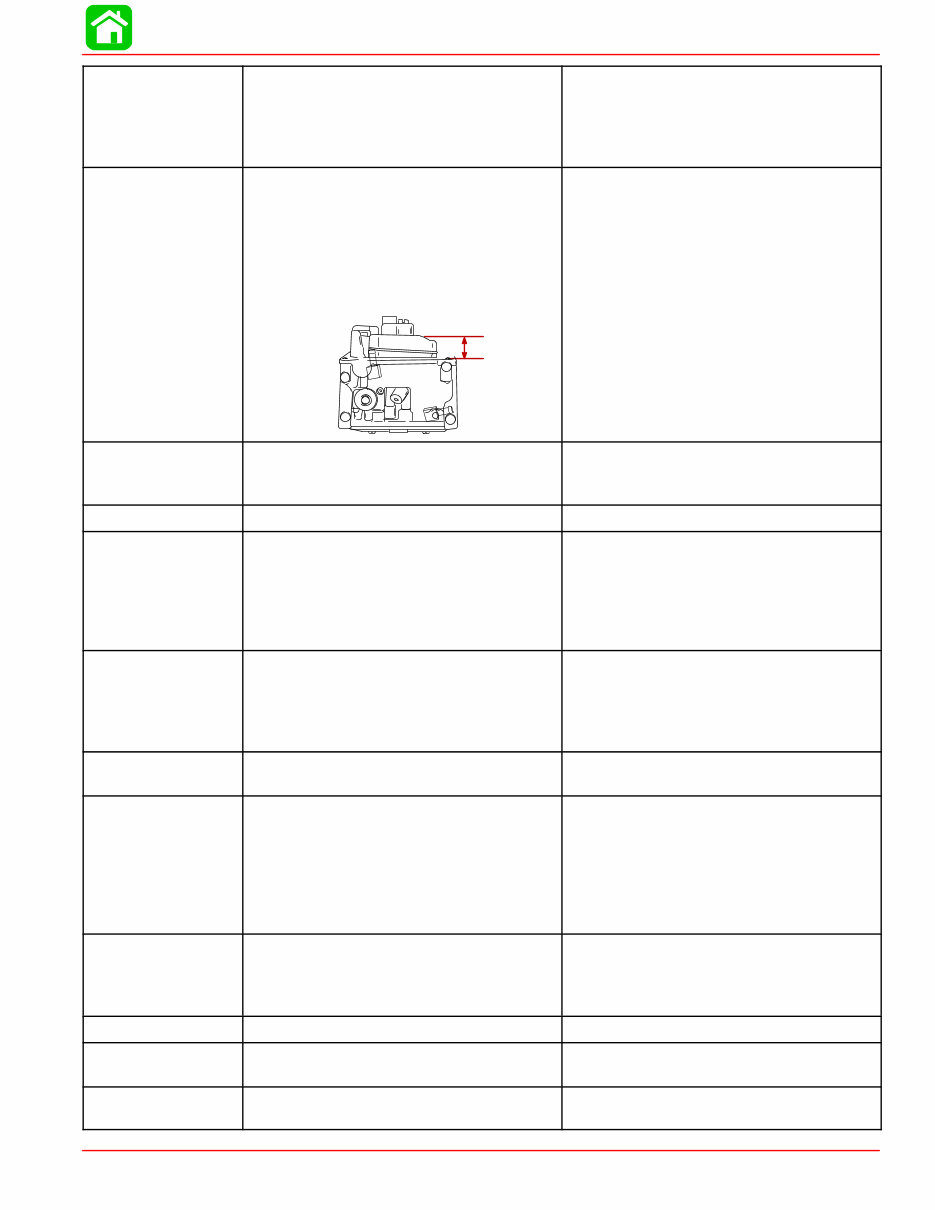
SPECIFICATIONS 90-858896 MAY 2000 Page 1A-3 FUEL SYSTEM Fuel Pump Type Fuel Pump: Pressure Plunger Stroke Fuel Tank Capacity External (Plunger/Diaphragm) 3-6 psi 0.23 - 0.38 in. (5.85 - 9.65 mm) Accessory CARBURETOR Idle rpm (Out Of Gear) Idle rpm (In Forward Gear) Wide Open Throttle rpm (WOT) Range Main Jet Size Pilot Jet Idle Mixture Screw Float Height 850 ± 25 rpm 725 ± 25 rpm 5500–6000 #98 #38 1 Turn out 0.47-0.63 in. (12.0-16.0 mm) CYLINDER BLOCK Type Displacement Number of Cylinders 4 Stroke Cycle – Over Head Camshaft 60.8 cu. in. (996 cc) 4 STROKE Length 2.953 in. (75 mm) CYLINDER BORE Diameter Standard Oversize-0.010 in. (0.25 mm) Oversize-0.020 in. (0.50 mm) Taper/Out of Round Maximum Bore Type 2.5591 in. (65 mm) 2.5689 in. (65.25 mm) 2.5787 in. (65.5 mm) 0.003 in. (0.08 mm) Cast Iron PISTON Piston Type O.D. at Skirt Standard Oversize-0.010 in. (0.25 mm) Oversize-0.020 in. (0.50 mm) Aluminum 2.5570 - 2.5578 in. (64.950 - 64.965 mm) 2.5669 - 2.5675 in. (65.2 - 65.215 mm) 2.5768 - 2.5774 in. (65.450 - 65.465 mm) PISTON CLEARANCE Piston to Cylinder Clearance 0.0014 - .0026 in. (0.035 - 0.065 mm) RINGS Ring End Gap (Installed) Top Middle Bottom (Oil Ring) Side Clearance: Top Middle 0.006 - 0.012 in. (0.15 - 0.03 mm) 0.012 - 0.020 in. (0.30 - 0.50 mm) 0.008 - 0.028 in. (0.20 - 0.70 mm) 0.0008 - 0.0024 in. (0.02 - 0.06 mm) 0.0008 - 0.0024 in. (0.02 - 0.06 mm) COMPRESSION RATIO Compression Ratio Cylinder Compression* (Electric Models Only, Cold Engine @ W.O.T.) 9.7:1 180 -210 psi (Peak) PISTON PIN Piston Pin Diameter 0.6285 - 0.6287 in. (15.965 - 15.970 mm) CONNECTING ROD Oil Clearance (Big End) Small End Inside Diameter 0.0008 - 0.0020 in. (0.020 - 0.052 mm) 0.6293 - 0.6298 in. (15.985 - 15.998 mm) CRANKSHAFT Main Bearing Clearance Crankshaft Run-out 0.0005 - 0.0017 in. (0.012 - 0.044 mm) 0.0018 in. (0.046 mm)
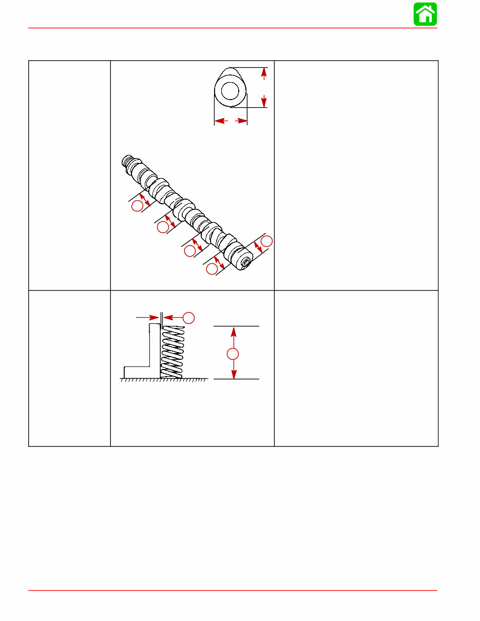
SPECIFICATIONS Page 1A-4 90-858896 MAY 2000 *NOTE: Manual start models are equipped with compression relief mechanism which will not allow compression testing. CAMSHAFT Camshaft Dimensions Intake “A” Exhaust “A” Intake “B” Exhaust “B” Run-out Limit Camshaft Bearing Diameter “b” A B b b b b b 1.214 - 1.222 in. (30.83 - 31.03 mm) 1.214 - 1.222 in. (30.83 - 31.03 mm) 1.020 - 1.028 in. (25.90 - 26.10 mm) 1.020 - 1.028 in. (25.90 - 26.10 mm) 0.0039 in. (0.1 mm) 1.4541 - 1.4549 in. (36.935 - 36.955 mm) VALVE SPRING Free Length “a” Tilt Limit “b” Compressed Pressure (Installed) Intake Exhaust Tilt Limit (Intake & Exhaust) Dir. of Winding (Intake & Exhaust) a b a b 1.491-1.569 in. (37.85-39.85 mm) Less than 0.060 in. (1.7 mm) 19.8 - 22.0 lbs. (9.0 - 10.0 kg) 19.8 - 22.0 lbs. (9.0 - 10.0 kg) 0.043 in. (1.1 mm) Left Hand
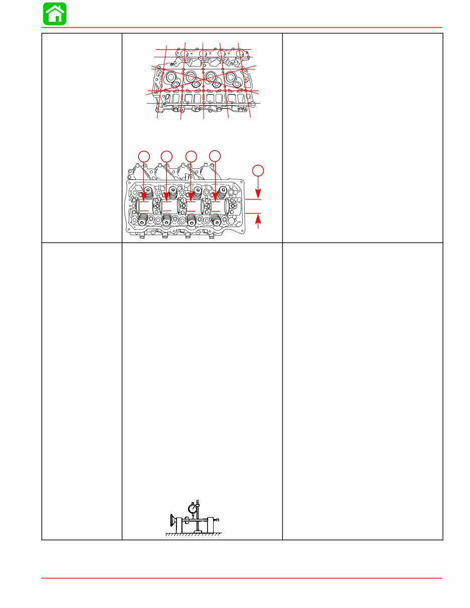
SPECIFICATIONS 90-858896 MAY 2000 Page 1A-5 CYLINDER HEAD Warp Limit * Lines indicate straight edge measurement Camshaft Bore Inside Diameter “a” a a a a a 0.004 in. (0.1 mm) 1.4567 - 1.4577 in. (37.000 - 37.025 mm) VALVES Valve/Valve Seat/Valve Guides: Valve Clearance (cold) Intake Exhaust Valve Dimensions: “A” Head Diameter Intake Exhaust “B” Face Width Intake Exhaust “C” Seat Width Intake Exhaust “D” Margin Thickness Intake Exhaust Stem Outside Diameter Intake Exhaust Guide Inside Diameter Intake Exhaust Stem To Guide Clearance Intake Exhaust Stem Run-out Limit (max.) 0.006 - 0.010 in. (0.15 - 0.25 mm) 0.010 - 0.014 in. (0.25 - 0.35 mm) 1.256 - 1.264 in. (31.9 - 32.1 mm) 1.020 - 1.028 in. (25.9 - 26.1 mm) 0.079 - 0.124 in. (2.00 - 3.14 mm) 0.079 - 0.124 in. (2.00 - 3.14 mm) 0.035 - 0.043 in. (0.9 - 1.1 mm) 0.035 - 0.043 in. (0.9 - 1.1 mm) 0.020 - 0.035 in. (0.5 - 0.9 mm) 0.020 - 0.035 in. (0.5 - 0.9 mm) 0.2156 - 0.2161 in. (5.475 - 5.490 mm) 0.2150 - 0.2156 in. (5.460 - 5.475 mm) 0.2165 - 0.2170 in. (5.500 - 5.512 mm) 0.2165 - 0.2170 in. (5.500 - 5.512 mm) 0.0004 - 0.0015 in. (0.010 - 0.037 mm) 0.0010 - 0.0020 in. (0.025 - 0.052 mm) 0.0006 in. (0.016 mm)
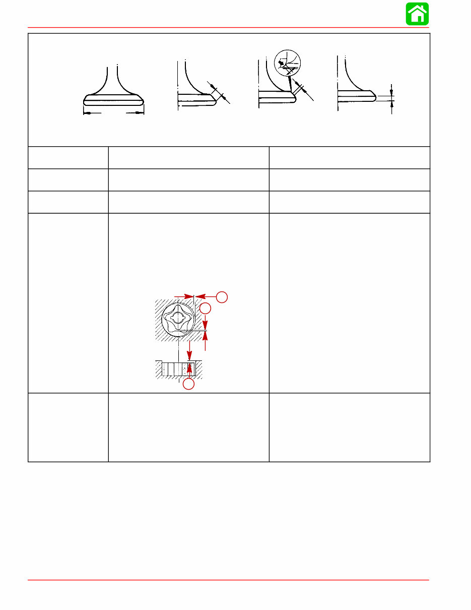
SPECIFICATIONS Page 1A-6 90-858896 MAY 2000 “A” “B” “C” “D” Valve Dimensions Head Diameter Face Width Seat Width Margin Thickness ROCKER SHAFT Outside Diameter 0.6288 - 0.6296 in. (15.971 - 15.991 mm) ROCKER ARM Inside Diameter of Bore 0.6299 - 0.6306 in. (16.000 - 16.018 mm) THERMOSTAT Valve Opening Temperature Full Open Temperature 118° F - 123° F (48° C - 51° C) 145° F (63° C) LUBRICATION SYSTEM Pump Type Engine Oil Pressure (Warm Engine) @ 3000 rpm Engine Oil Pan Capacity Oil Pump: Outer Rotor to Housing “a” Inner Rotor to Outer Rotor “b” Rotor to Housing “c” a b c a b c Trochoid 30-40 psi (207-278 kPa) Either 3 Qts. or 3 Liters 0.0045 - 0.009 in. (0.11 - 0.23 mm) 0.005 in. (0.12 mm) 0.0015 - 0.003 in. (0.04 - 0.08 mm) MID-SECTION Transom Height: Long Shaft Steering Pivot Range: Tiller Remote Full Tilt Up Angle Allowable Transom Thickness 20 in. (51 cm) 90° 60° 71° 2-3/4 in. (69.8 mm)
Mercury Mariner 50 HP 4-stroke Factory Service Repair Manual is a comprehensive resource for repairing and adjusting your Mercury Mariner 50 HP 4-stroke engine. It is designed to be a convenient reference for both professional mechanics and DIY enthusiasts. The manual provides detailed explanations for installation, removal, disassembly, assembly, repair, and check procedures, presented in a sequential order.
Serial Numbers: US 0G231123
This manual is known by various names:
Mercury Mariner 50 HP 4-stroke service manual
Mercury Mariner 50 HP 4-stroke repair manual
Mercury Mariner 50 HP 4-stroke workshop manual
Mercury Mariner 50 HP 4-stroke shop manual
All the above manuals are one and the same.
Upon purchase, you will have immediate access to the manual, allowing you to get the job done quickly.
This manual is divided into chapters, and the manual index includes:
Important information
Electrical
Fuel system
Powerhead
Mid-section
Gear housing
Attachment/control linkage
Each chapter is further divided into sections, with each section containing sub-sections. The manual includes exploded diagrams at the start of each removal and disassembly section to aid in identifying parts and clarifying procedure steps. The manual is available in PDF format, allowing for easy printing of specific pages or the entire manual.
Recently Viewed
5,521,897Happy Clients
2,594,462eManuals
1,120,453Trusted Sellers
15Years in Business
Price:
Actual Price:
Mercury Mariner 50 HP 4-stroke Factory Service Repair Manual