90-814676R1 DECEMBER 1996 IMPORTANT INFORMATION - 1-1 Propeller Information For in-depth information on marine propellers and boat performance - written by marine engineers - see your Authorized Dealer for the illustrated “What You Should Know About Quicksilver Propellers and Boat Performance Information” (Part No. 90-86144). How to Use this Manual The manual is divided into SECTIONS (shown, right) which represents major components and systems. Some SECTIONS are further divided into PARTS. Each PART has a title page. A “Table of Contents” for the particular PART is printed on the back of the title page. SECTIONS and PARTS are listed on the “Service Manual Outline” sheet which immediately follows the cover of this book. Section Section Heading 1 2 3 4 5 6 7 8 Important Information Electrical and Ignition Fuel System and Carburetion Powerhead Mid-Section Lower Unit Outboard Installation/Attachments Oil Injection System
1-2 - IMPORTANT INFORMATION 90-814676R1 DECEMBER 1996 General Specifications Model 40 Horsepower 40 Engine Type 4 Cylinder, In-Line, Two-Stroke Full Throttle RPM Range 5000-5500 Idle RPM Range (in Forward Gear) 600-700 Piston Displacement 44 cu. in. (721cc) Cylinder Bore Standard 2.565 in. (65.151mm) Stroke 2.125 in. (53.975mm) Ignition Type Thunderbolt Capacitor Discharge Firing Order 1-3-2-4 Recommended Spark Plug NGK BUHW-2 Gear Selection Forward - Neutral - Reverse Gear Ratio 2:1 Gear Housing Lubricant Capacity 12.5 fl. oz. (370ml) Outboard Weight (ELPTO) 192 lbs. (87kg) Carburetion 2 Carburetors, Center Bowl Recommended Gasoline Any leaded or unleaded (lead-free) gasoline, with a minimum posted octane rating of 86 (research octane number 90) Remote Fuel Tank Capacity: - U.S. Gallons - Imperial Gallons - Liters 6.6 5.5 25 Recommended Oil Quicksilver 2-Cycle Outboard Oil Gasoline/Oil Ratio 50:1 Oil Tank Capacity* 0.935 gal. (3.54 Liters) Maximum Operation at Full Throttle* 7 Hours Oil Remaining when Warning Buzzer Sounds* 7.5 fl. oz. Approximate Running Time Remaining at Wide Open Throttle when Buzzer Sounds* 30 Minutes Recommended Battery Rating Minimum Reserve Capacity rating of 100 Minutes and Cold Cranking Amperage of 350 Amperes *Specification for Oil Injected Model
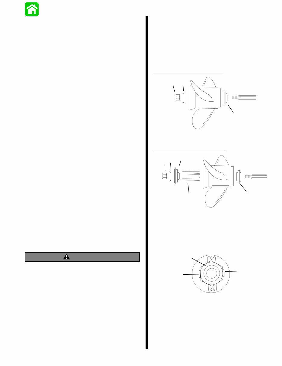
90-814676R1 DECEMBER 1996 IMPORTANT INFORMATION - 1-3 Propeller Selection 1. Select a propeller that will allow the engine to op- erate at or near the top of the recommended full throttle RPM range (listed in “Specifications,” preceding) with a normal load. Maximum engine speed (RPM) for propeller selection exists when boat speed is maximum and trim is minimum for that speed. (High RPM, caused by an excessive trim angle, should not be used in determining cor- rect propeller.) Normally, there is a 150-350 RPM change between propeller pitches. 2. If full throttle operation is below the recom- mended range, the propeller MUST BE changed to a lower pitch to prevent loss of performance and possible engine damage. 3. For better acceleration, such as is needed in wa- ter skiing, propping up to 500 RPM above the rec- ommended range is advised. Continuous opera- tion above the recommended maximum RPM, however, is not permissible. 4. After initial propeller installation, the following common conditions may require that the propel- ler be changed to a lower pitch: a. Warmer weather and great humidity will cause an RPM loss. b. Operating in a higher elevation causes an RPM loss. c. Operating with a damaged propeller or a dirty boat bottom or gear housing will cause an RPM loss. d. Operation with an increased load (additional passengers, equipment, pulling skiers, etc.). Propeller Installation WARNING If the propeller shaft is rotated while the engine is in gear, there is the possibility that the engine will crank over and start. To prevent this type of accidental engine starting and possible serious injury caused from being struck by a rotating pro- peller, always shift outboard to neutral position and remove spark plug leads when you are serv- icing the propeller. Coat the propeller shaft with Quicksilver Anti-Corro- sion Grease or 2-4-C Marine Lubricant with Teflon. IMPORTANT: To prevent the propeller hub from corroding and seizing to the propeller shaft, es- pecially in salt water, always apply a coat of the recommended lubricant to the entire propeller shaft at the recommended maintenance intervals and also each time the propeller is removed. Flo-Torq I Drive Hub Propellers a c b a - Forward Thrust Hub b - Propeller Nut Retainer c - Propeller Nut Flo-Torq II Drive Hub Propellers a c b d e a - Forward Thrust Hub b - Replaceable Drive Sleeve c - Rear Thrust Hub d - Propeller Nut Retainer e - Propeller Nut 1. Tighten propeller nut to 55 lb.ft. (75 N·m). Bend tabs against nut. a b b a - Propeller Nut - Torque To 55 lb. ft. (75 N·m) b - Bend Tabs Against Nut
1-4 - IMPORTANT INFORMATION 90-814676R1 DECEMBER 1996 Trim “In” Angle Adjustment WARNING Operating some boats with outboard trimmed to the full “in” trim angle [not using trim adjustment bolt (a)] at planing speed will cause undesirable and/or unsafe steering conditions. Each boat must be water tested for handling characteristics after outboard installation and after any trim ad- justments. IMPORTANT: Some boat/outboard combina- tions, that do not use the trim adjustment pin (a) and are trimmed to the full “in” trim angle, will not experience any undesirable and/or unsafe steer- ing conditions during planing speed. Thus, not using trim adjustment pin may be desired. How- ever, some boats with outboard trimmed to the full “In” trim angle at planing speeds will cause undesirable and/or unsafe steering conditions. If these steering conditions are experienced, un- der no circumstances should the outboard be operated without the trim adjustment pin and without the pin adjusted in the proper holes to prevent unsafe handling characteristics. Water test the boat not using the trim adjustment pin. If undesirable and/or unsafe steering conditions are experienced (boat runs with nose down), install trim adjustment pin in proper hole to prevent unsafe han- dling characteristics. 50157 Power Trim System (Models with Power Trim) General Information The power trim system is filled at the manufacturer and is ready for use. Trim outboard through entire trailering range several times to remove any air from the system. The trim system is pressurized and is not externally vented. The outboard can be raised or lowered manually by loosening the manual release valve 2 to 3 turns coun- terclockwise. The trim “out” angle of this outboard is not adjustable. The trim system has an internal valve which will auto- matically stop the outward trim travel at 200 when en- gine RPM is approximately 2000 RPM or higher; out- board also has to be in water and in gear. The outboard can be operated beyond the 200 trim limit for operating outboard in shallow water if engine RPM is kept below approximately 2000 RPM. 50158 50146 a - Fill Screw (System is Pressurized, DO NOT Open Unless Outboard is Tilted to Full Up Position) b - Manual Tilt Release Valve Location
90-814676R1 DECEMBER 1996 IMPORTANT INFORMATION - 1-5 Checking Trim System Fluid Level IMPORTANT: This trim system is pressurized. Remove fill screw when outboard is trimmed to the full “up” position. Retighten fill screw secure- ly. 1. Trim outboard to full “up” position. Engage tilt lock level (a). Trim system fluid can only be checked when outboard is in this position. 50157 2. Remove fill screw and check fluid level. Fluid lev- el should be to bottom of threads in fill hole (b). 3. If necessary, add Quicksilver Power Trim & Steering Fluid or; Automatic Transmission Fluid (ATF) Type F, FA or Dexron 11 fluid to trim system. 4. Reinstall fill screw. b Trimming (Models with Power Trim) NOTE: Because varying hull designs react differently in various degrees of rough water, it is recommended to experiment with trim positions to determine wheth- er trimming up or down will improve the ride in rough water. When trimming your outboard from a mid-trim posi- tion (trim tab in neutral straight fore-and-aft position), you can expect the following results: Trimming Outboard “Out” (“Up”) Characteristics WARNING Excessive trim “out” also may reduce the stabil- ity of some high speed hulls. To correct instabili- ty at high speed, reduce the power GRADUALLY and trim the outboard “In” slightly before resum- ing high speed operation. (Rapid reduction in power will cause a sudden change of steering torque and may cause additional momentary boat instability.) 1. Will lift bow of boat, generally increasing top speed. 2. Transfers steering torque harder to left on stan- dard or slightly elevated transom installation (single outboard). 3. Increases clearance over submerged objects. 4. In excess, can cause porpoising and/or ventila- tion. 5. If trimmed out beyond the water pickup, reduced water supply can cause serious overheating. Trimming Outboard “In” (“Down”) Characteristics WARNING Excessive speed at minimum trim “in” may cause undesirable and/or unsafe steering condi- tions. Each boat should be tested for handling characteristics after any adjustment is made to the trim angle (trim adjustment pin relocation). 1. Will help planing off, particularly with a heavy load. 2. Usually improves ride in choppy water.
1-6 - IMPORTANT INFORMATION 90-814676R1 DECEMBER 1996 3. In excess, can cause boat to veer to the left or right (bow steer). 4. Transfers steering torque harder to right (or less to the left) on single outboard installations. 5. Improves planing speed acceleration. Trim Tab Adjustment 1. Check trim tab position as follows: a. Operate boat at the speed at which it would normally be operated. b. If the boat pulls to the right (starboard), the trailing edge of trim tab must be moved to the right. If the boat pulls to the left (port), the trail- ing edge of trim tab must be moved to the left. 2. If necessary, adjust trim tab as follows: a. Shift outboard control into neutral and turn ignition key to “Off” position. b. Remove plug from rear of drive shaft housing and loosen bolt and trim tab. c. If boat pulls to the left, adjust trailing edge of trim tab to the left. If boat pulls to the right, ad- just trailing edge of trim tab to the right. d. Tighten trim tab bolt securely and replace plug. e. Operate boat per “Check trim tab position as follows,” preceding, to check trim tab setting. If necessary, readjust trim tab. 22750 a - Anti-Ventilation Plate b - Adjustable Trim Tab c - Plug Boat Performance Test Instructions WARNING A tight grip on the steering wheel/tiller handle is always advisable and is required when accelerat- ing, decelerating or when trimming the boat. On models with Power Trim, upon reaching cruising speed, the outboard should be trimmed to obtain a balanced steering condition. While trimming, steering loads will vary and will pull in one direc- tion until a balanced condition has been attained. If the outboard is trimmed past the balanced steering condition, the steering wheel/tiller han- dle then will have a tendency to pull in the oppo- site direction. Excessive trimming past the bal- anced steering position will result in increased steering loads and, in most boat applications, a decrease in performance. CAUTION When trimming boat with dual outboards, both outboards should be at approximately the same tilt angle and be tilted out (up) simultaneously (to prevent boat from pitching side-to-side) until de- sired boat attitude is achieved. Outboards can then be trimmed individually to precisely adjust boat trim angle and pitch. 1. With boat in water, trim the outboard(s) (trim but- ton in remote control handle) so that the decal on the side of cowl is horizontal. This is a typical av- erage setting that should give reasonable accel- eration and top speed. 2. Go for a short familiarization ride at various throttle and trim settings BEFORE starting test- ing. NOTE: Instruments should be read with eye directly in front to eliminate any error in reading the instru- ments. 3. When making either top speed or acceleration runs, best accuracy will be obtained by running with or against any wind. Side winds require driv- ing in a constant turn to keep the boat moving straight ahead. If winds are 10 MPH (16 km/hr) or greater, it is suggested that all acceleration runs be made downwind.
* WOT is wide-open-throttle 90-814676R1 DECEMBER 1996 IMPORTANT INFORMATION - 1-7 4. The top speed WOT (wide-open-throttle) test should be done with the boat normally loaded (to duplicate actual running conditions). Operate boat in gear at WOT and check RPM. Engine RPM must be within the recommended full throttle RPM range (listed in the Operation and Maintenance Manual). NOTE: When performing an acceleration test, it is recommended that a stop watch be used to improve testing accuracy. A wrist watch with a second hand may also be substituted. 5. An acceleration test can also be performed if de- sired. Start the test with boat motionless in the water and outboard in neutral. A stop watch should be started as the throttle is quickly pushed to WOT (wide-open-throttle). Stop the watch as the speedometer needle sweeps past 20 MPH (32 km/hr). Several runs should be made to as- sure a good average. 6. Prop “break loose” (sudden higher RPM), if not excessive, in some cases can be beneficial dur- ing acceleration. If undesirable “break loose” oc- curs, it can be decreased by trimming the out- board further under. If it remains excessive with all similar propellers, the outboard must be low- ered. 7. It is suggested that all applicable data be re- corded on a chart (such as that illustrated, follow- ing) and retained for future reference. 8. After several propellers of different pitch and/or design have been tried, select one that best serves the general purpose of the boat. The se- lected propeller should enable the engine to op- erate within its recommended full throttle RPM range, without excessive propeller “break loose” during acceleration or turns. A second propeller that would make both a suitable spare or a spe- cial purpose alternate might also be desirable. NOTE: A higher pitch often gives best top speed, but the next lower pitch gives adequate top speed with much better acceleration. Boat Test Chart (Example)
1-8 - IMPORTANT INFORMATION 90-814676R1 DECEMBER 1996 Lubrication Points Item No. Description Type of Lubricant Fresh Water Frequency Salt Water Frequency 1 Throttle/Shift Linkage Pivot Points Quic sil er E ery E ery 2 Upper Shift Shaft Quicksilver 2-4-C E ery E ery 3 Tilt Lock Lever 2-4-C M ri e Every ys Every ys 4 Swivel Pin Marine Lubricant 60 Days 30 Days 5 Ride Guide Steering Cable 6 Tilt Tube 7 Steering Link Rod Pivot Points SAE 30W Motor Oil Every 60 Days Every 30 Days 8 Propeller Shaft Quicksilver - Special Lubricant 101 - Anti-Corrosion Grease - 2-4-C Marine Lubricant Once in Season Every 60 Days 9 Starter Motor Pinion Gear SAE 10W Motor Oil Once in Season Every 60 Days L Gear Housing Bearing Carrier and Cover Nut Quicksilver - Special Lubricant 101 - 2-4-C Marine Lubricant After first 20 hours, then once in season er ousi Quic sil er Check and fill after first 10 days, then every 30 days Check and fill after first 10 days, then every 30 days j Gear Housing Quicksilver Gear Lube Drain and refill after 1st 25 hours, then after every 100 hours, or once a year before storing Drain and refill after 1st 25 hours, then after every 100 hours, or once a year before storing Z Engine Crankshaft Splines to Drive Shaft Splines Quicksilver 2-4-C Marine Lubricant Once in Season Once in Season L Refer to lubrication instructions outlined in “Salt Water Corrosion - Gear Housing Bearing Carrier and Cover Nut” of this section (see “Table of Contents”). j Refer to “Gear Housing Lubrication” of this section (see “Table of Con- tents”). Z Refer to “Gear Housing Removal and Installation” (Section 5). 50195 1 - Throttle/Shift Linage Pivot Pint Lubrication 54634 2 - Upper Shift Shaft Lubrication
This Service Repair Manual is the ultimate guide for maintaining and repairing the Mercury Outboard 30 jet / 40 (4cyl). It contains easy-to-understand text sections accompanied by high-quality diagrams and instructions, making it an essential tool for both professional mechanics and DIY enthusiasts.
The manual covers the following models:
30 Jet/40 (4cylinder)
It includes information for serial numbers:
US 0C159200 and above
Belgium 9570305 and above
Canada 0A748269 and above
The Service Repair Manual comprehensively covers the following sections:
Section 1 - Important Information
Section 2 - Electrical & Ignition
Ignition System
Battery, Charging System & Starting System
Timing, Synchronizing & Adjustment
Wiring Diagrams
Section 3 - Fuel System & Carburetion
Section 4 - Powerhead
Section 5 - Mid-Section
Clamp/Swivel Bracket & Drive Shaft Housing
Power Trim (Design I, II, III, IV)
Manual Tilt System (Design I, II, III, IV)
Section 6 - Lower Unit
Lower Unit
Jet Drive
Section 7 - Outboard Motor Installation/Attachments
Tiller Handle and Co-Pilot
Rewind Starter
Section 8 - Oil Injection System
The manual is available in file format and is compatible with all versions of Windows & Mac. It is presented in English and requires Adobe Reader & Win for access. With instant access, no shipping costs, and no need to wait for a CD-ROM, this manual is designed to save time and money for all users. The step-by-step instructions make it easy for any skill level, and all pages are printable for convenience.
Recently Viewed
5,521,897Happy Clients
2,594,462eManuals
1,120,453Trusted Sellers
15Years in Business
Price:
Actual Price:
Mercury Outboard 30 jet / 40 (4cyl) 2-stroke Service Manual