Mercury Mariner 40 HP 3-Cyl OEM Service & Repair Manual
What's Included?
Lifetime Access
Fast Download Speeds
Online & Offline Access
Access PDF Contents & Bookmarks
Full Search Facility
Print one or all pages of your manual
MODELS United States 0G531301 and ABOVE . . Belgium 09974454 and ABOVE . . . . . . . With Serial Numbers SERVICE MANUAL 40·50·55·60 Printed in U.S.A. 1997, Mercury Marine 90-852572R1 JANUARY 1998
90-852572R1 JANUARY 1998 i Notice Throughout this publication, “Dangers”, “Warnings” and “Cautions” (accompanied by the International HAZARD Symbol ) are used to alert the mechanic to special instructions concerning a particular service or operation that may be hazardous if performed in- correctly or carelessly. OBSERVE THEM CARE- FULLY! These “Safety Alerts” alone cannot eliminate the haz- ards that they signal. Strict compliance to these spe- cial instructions when performing the service, plus “Common Sense” operation, are major accident pre- vention measures. DANGER DANGER - Immediate hazards which WILL result in severe personal injury or death. WARNING WARNING - Hazards or unsafe practices which COULD result in severe personal injury or death. CAUTION Hazards or unsafe practices which could result in minor personal injury or product or property damage. Notice to Users of This Manual This service manual has been written and published by the Service Department of Mercury Marine to aid our dealers’ mechanics and company service per- sonnel when servicing the products described here- in. It is assumed that these personnel are familiar with the servicing procedures of these products, or like or similar products manufactured and marketed by Mercury Marine, that they have been trained in the recommended servicing procedures of these prod- ucts which includes the use of mechanics’ common hand tools and the special Mercury Marine or recom- mended tools from other suppliers. We could not possibly know of and advise the service trade of all conceivable procedures by which a ser- vice might be performed and of the possible hazards and/or results of each method. We have not under- taken any such wide evaluation. Therefore, anyone who uses a service procedure and/or tool, which is not recommended by the manufacturer, first must completely satisfy himself that neither his nor the products safety will be endangered by the service procedure selected. All information, illustrations and specifications con- tained in this manual are based on the latest product information available at the time of publication. As re- quired, revisions to this manual will be sent to all deal- ers contracted by us to sell and/or service these prod- ucts. It should be kept in mind, while working on the prod- uct, that the electrical system and ignition system are capable of violent and damaging short circuits or se- vere electrical shocks. When performing any work where electrical terminals could possibly be grounded or touched by the mechanic, the battery cables should be disconnected at the battery. Any time the intake or exhaust openings are exposed during service they should be covered to protect against accidental entrance of foreign material which could enter the cylinders and cause extensive inter- nal damage when the engine is started. It is important to note, during any maintenance proce- dure replacement fasteners must have the same measurements and strength as those removed. Numbers on the heads of the metric bolts and on the surfaces of metric nuts indicate their strength. Ameri- can bolts use radial lines for this purpose, while most American nuts do not have strength markings. Mis- matched or incorrect fasteners can result in damage or malfunction, or possibly personal injury. There- fore, fasteners removed should be saved for reuse in the same locations whenever possible. Where the fasteners are not satisfactory for re-use, care should be taken to select a replacement that matches the original.
ii 90-852572R1 JANUARY 1998 Cleanliness and Care of Outboard Motor A marine power product is a combination of many machined, honed, polished and lapped surfaces with tolerances that are measured in the ten thousands of an inch./mm. When any product component is serv- iced, care and cleanliness are important. Throughout this manual, it should be understood that proper cleaning, and protection of machined surfaces and friction areas is a part of the repair procedure. This is considered standard shop practice even if not specif- ically stated. Whenever components are removed for service, they should be retained in order. At the time of instal- lation, they should be installed in the same locations and with the same mating surfaces as when re- moved. Before raising or removing and outboard engine from a boat, the following precautions should be adhered to: 1. Check that flywheel is secured to end of crank- shaft with a locknut and lifting eye is threaded into flywheel a minimum of 5 turns. 2. Connect a hoist of suitable strength to the lifting eye. In addition, personnel should not work on or under an outboard which is suspended. Outboards should be attached to work stands, or lowered to ground as soon as possible. We reserve the right to make changes to this manual without prior notification. Refer to dealer service bulletins for other pertinent in- formation concerning the products described in this manual. Page Numbering Two number groups appear at the bottom of each page. The example below is self-explanatory. EXAMPLE: 90-826148R1 JANUARY 1997 LOWER UNIT - 6A-7 Revision No. 1 Month of Printing Year of Printing Section Description Section Number Part of Section Letter Page Number
Important Information Electrical Fuel System Powerhead Mid-Section Lower Unit Attachments/ Control Linkage Manual Starter 8 1 2 3 4 5 6 7 90-852572R1 JANUARY 1998 iii Service Manual Outline Section 1 - Important Information A - Specifications B - Maintenance C - General Information D - Outboard Installation Section 2 - Electrical A - Ignition B - Charging & Starting System C - Timing, Synchronizing & Adjusting D - Wiring Diagrams Section 3 - Fuel System A - Fuel Pump B - Carburetor C - Oil Injection D - Emissions Section 4 - Powerhead Section 5 - Mid-Section A - 40/50 Clamp/Swivel Brackets & Drive Shaft Housing B - 55/60 Clamp/Swivel Brackets & Drive Shaft Housing C - 40/50 Power Trim D - 55/60 Power Trim E - 40/50 Manual Tilt F - 55/60 Manual Tilt Section 6 - Lower Unit A - 40/50 Lower Unit B - 55/60 Lower Unit C - 60 Bigfoot D - Jet Drive Section 7 - Attachments/Control Linkage A - Throttle/Shift Linkage B - Tiller Handle Section 8 - Manual Starter
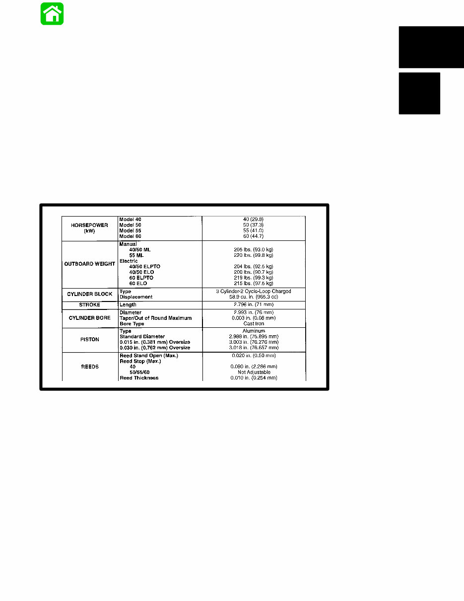
90-852572R1 JANUARY 1998 IMPORTANT INFORMATION - 1A-1 Specifications Models 40/50/55/60 HORSEPOWER (kW) Model 40 Model 50 Model 55 Model 60 40 (29.8) 50 (37.3) 55 (41.0) 60 (44.7) OUTBOARD WEIGHT Manual 40/50 ML 55 ML Electric 40/50 ELPTO 40/50 ELO 60 ELPTO 60 ELO 205 lbs. (93.0 kg) 220 lbs. (99.8 kg) 204 lbs. (92.5 kg) 200 lbs. (90.7 kg) 219 lbs. (99.3 kg) 215 lbs. (97.5 kg) CYLINDER BLOCK Type Displacement 3 Cylinder-2 Cycle-Loop Charged 59 cu. in. (967 cc) STROKE Length 2.796 in. (71 mm) CYLINDER BORE Diameter Taper/Out of Round Maximum Bore Type 2.993 in. (76 mm) 0.003 in. (0.08 mm) Cast Iron PISTON Type Standard Diameter 0.015 in. (0.381 mm) Oversize 0.030 in. (0.762 mm) Oversize Aluminum 2.988 in. (75.895 mm) 3.003 in. (76.276 mm) 3.018 in. (76.657 mm) REEDS Reed Stand Open (Max.) Reed Stop (Max.) 40 50/55/60 Reed Thickness 0.020 in. (0.50 mm) 0.090 in. (2.286 mm) Not Adjustable 0.010 in. (0.254 mm) FUEL SYSTEM Recommended Gasoline Recommended Oil Break-in Gasoline/Oil Ratio Manual Start Models Electric Start Models After Break-in Gasoline/Oil Ratio Manual Start Models Electric Start Models Fuel Pressure @ Idle @ W.O.T. Unleaded-87 Octane Minimum Quicksilver TC-WII or TC-W3 2 Cycle Outboard Oil Pre-mixed Gasoline and Oil 25:1 50:1 (In Fuel Tank) Pre-mixed Gasoline and Oil 50:1 Straight Gasoline 3.5 PSI (24 kPa) 6.0 PSI (41 kPa)
1A-2 - IMPORTANT INFORMATION 90-852572R1 JANUARY 1998 GEAR HOUSING 40/50 Gear Ratio Gearcase Capacity Lubricant Type Forward Gear Number of Teeth Pinion Gear Number of Teeth Pinion Height Forward Gear Backlash Water Pressure @ Idle @ W.O.T. Pressure Test 55/60 Gear Ratio Gearcase Capacity Lubricant Type Forward Gear Number of Teeth Pinion Gear Number of Teeth Pinion Height Forward Gear Backlash Water Pressure @ Idle @ W.O.T. Pressure Test 60 Bigfoot Gear Ratio Gearcase Capacity Lubricant Type Forward Gear Number of Teeth Pinion Gear Number of Teeth Pinion Height Forward Gear Backlash Water Pressure @ Idle @ W.O.T. Pressure Test 1.83:1 14.9 fl. oz. (440 mL) Quicksilver Gear Lube-Premium Blend 22 Spiral/Bevel 12 Spiral/Bevel 0.025 in. (0.64 mm) No Adjustment 0.5-1.5 PSI (3-10 kPa) 5.0–7.0 PSI (35-48 kPa) 10-12 PSI (69-83 kPa) for 5 Minutes 1.64:1 11.5 fl. oz. (340 mL) Quicksilver Gear Lube-Premium Blend 23 14 0.025 in. (0.64 mm) Pinion Gear Locating Tool (91-817008A2) 0.013-0.019 in. (0.33-0.48 mm) 1–3 PSI (7-20 kPa) 7–12 PSI (48-83 kPa) 10-12 PSI (69-83 kPa) for 5 Minutes 2.3:1 22.5 fl. oz. (655 mL) Quicksilver Gear Lube-Premium Blend 30 13 0.025 in. (0.64 mm) 0.012 in.-0.019 in. (0.30 mm-0.48 mm) 10-15 PSI (69-103 kPa) @ 5250 RPM 2-7 PSI (14–48 kPa) 10-15 PSI (69-104 kPa) 10-12 PSI (69-83 kPa) for 5 Minutes
90-852572R1 JANUARY 1998 IMPORTANT INFORMATION - 1A-3 STARTING SYSTEM Manual Start Electric Start Starter Draw (Under Load) Battery Rating Recoil Starter 125 Amperes Min. Reserve Cap. Rating of 100 Min. and CCA of 350 Amperes IGNITION SYSTEM Type Spark Plug Type Spark Plug Gap Firing Order Capacitor Discharge NGK BP8H-N-10 *NGK BPZ8H-N-10 0.040 in. (1.0mm) 1-2-3 CHARGING SYSTEM Alternator Output Electric Models Manual Models (Not Regulated) Single Phase (12 Pole) 16 Amperes @ 3000 RPM 9 Amperes @ 3000 RPM 7 Amperes @ 3000 RPM CARBURETOR Idle RPM Wide Open Throttle (W.O.T.) RPM Idle Mixture Screw Adjustment Preset (Turns Out) Float Adjustment Float Level Main Jet Model 40 (WME-53, 69) Model 50 (WME-68) Model 55 (WME-57) Model 60 (WME-58) 675 ± 25 5000-5500 1 1 / 4 ± 1 / 4 9 / 16 in. (14 mm) 0.044 in. 0.052 in. 0.058 in. 0.060 in. OIL INJECTION Recommended Oil Oil Tank Capacity/Approx. Time Reserve Capacity/Approx. Time Oil Output With Engine RPM of 1500 and Oil Pump @ W.O.T. Model 40 Model 50/60 Quicksilver TC-WII or TC-W3 2 Cycle Outboard Oil 3.0 qts. (2.8 L) 7 hours 14.5 fl. oz. (0.43 L) 1 / 2 hour 15.0 ± 3.0 cc of oil in 10 minutes 22.0 ± 3.0 cc of oil in 10 minutes TIMING Idle Maximum Timing @ Cranking Speed -Model 40/50/60 -Model 55/60 Seapro-Marathon @ 5000 RPM – Model 40/50/60 – Model 55/60 Seapro-Marathon T.D.C. ± 2° 24° B.T.D.C. 18° B.T.D.C. 22° B.T.D.C. 16° B.T.D.C. TEMPERATURE SWITCH Temperature Normal 190°F ± 8° (88°C ± 4°C) 170°F ± 8° (77°C ± 4°C) Open - No Continuity Closed - Full Continuity Open - No Continuity *Suppressor (resistor) spark plug
1A-4 - IMPORTANT INFORMATION 90-852572R1 JANUARY 1998 Propeller Information Charts Mercury/Mariner 40 HP (3 Cyl.) Wide Open Throttle RPM: 5000-5500 Recommended Transom Heights : 15”, 20” Right Hand Rotation Standard Gear Reduction : 1.83:1 Diameter Pitch No. of Blades Material Approx. Gross Boat Wgt. (lbs) Approx. Boat Length Speed Range (mph) Propeller Part Number 10” 19” 3 Alum Up to 900 Up to 14’ 41-49 48-73146A40 10” 17” 3 Alum Up to 900 Up to 14’ 35-43 48-73144A40 10” 16” 3 SS Up to 1200 Up to 15’ 32-40 48-91818A5 10” 16” 3 Alum Up to 1200 Up to 15’ 32-40 48-73142A40 10-1/8” 15” 3 SS 1000-1500 13-15’ 28-37 48-855862A5 10-1/8” 15” 3 Alum 1000-1500 13-15’ 28-37 48-73140A40 10-3/8” 14” 3 Alum 1100-1700 14-16’ 25-34 48-816706A40 10-1/4” 14” 3 SS 1100-1700 14-16’ 25-34 48-855860A5 10-1/4” 14” 3 Alum 1100-1700 14-16’ 25-34 48-73138A40 10-1/2” 13” 3 Alum 1300-2100 14-17’ 21-31 48-816704A40 10-3/8” 13” 3 SS 1300-2100 14-17’ 21-31 48-855858A5 10-3/8” 13” 3 Alum 1300-2100 14-17’ 21-31 48-73136A40 10-3/4” 12” 3 Alum 1500-2500 15-19’ 18-27 48-816702A40 10-5/8” 12” 3 SS 1500-2500 15-19’ 18-27 48-855856A5 10-5/8” 12” 3 Alum 1500-2500 15-19’ 18-27 48-73134A40 10-7/8” 11” 3 Alum 1800-3500 16-21’ 14-24 48-85632A40 11-1/4” 10” 3 Alum 2000+ 17’+ 11-21 48-73132A40 11-5/8” 11” 3 SS 1800-3500 16-21’ 14-24 48-823478A5 11-5/8” 10-1/2” 3 Alum 2000+ 17’+ 13-23 48-827312A10 12-1/4” 9” 3 Alum 2500+ 18’+ 8-17 48-87818A10 12-1/4” 9” 3 SS 2500+ 18’+ 8-17 48-97868A10 12-1/2” 8” 3 Alum 3000+ 20’+ 1-14 48-42738A10
The Mercury Mariner 40 HP 3-Cyl OEM Service & Repair Manual is a comprehensive resource for repairing and adjusting your Mercury Mariner 40 HP 3-Cyl engine. It is designed to be a valuable reference for both professional mechanics and DIY enthusiasts. The manual provides detailed explanations for installation, removal, disassembly, assembly, repair, and check procedures, presented in a sequential order.
Serial Numbers: US 0G531301 and above, Belgium 09974454 and above
This manual is known by various names, including:
Mercury Mariner 40 HP 3-Cyl OEM service manual
Mercury Mariner 40 HP 3-Cyl OEM repair manual
Mercury Mariner 40 HP 3-Cyl OEM workshop manual
Mercury Mariner 40 HP 3-Cyl OEM shop manual
It is important to note that all of the above manuals are identical.
Upon purchase, you will have immediate access to the manual, enabling you to complete repairs promptly. The manual is divided into chapters, and the index includes:
Important information
Electrical
Fuel system
Powerhead
Mid-section
Lower unit
Attachments/control linkage
Manual starter
Each chapter is further divided into sections, with each section containing subsections. The manual includes exploded diagrams at the beginning of each removal and disassembly section to aid in identifying parts and clarifying procedure steps. The manual is available in PDF format, allowing for easy printing of specific pages or the entire manual.
Recently Viewed
5,521,897Happy Clients
2,594,462eManuals
1,120,453Trusted Sellers
15Years in Business
Price:
Actual Price:
Mercury Mariner 40 HP 3-Cyl OEM Service & Repair Manual