

MERCURY MARINER 30HP 40HP Service Manual
What's Included?
Fast Download Speeds
Offline Viewing
Access Contents & Bookmarks
Full Search Facility
Print one or all pages of your manual
1
A
SPECIFICATIONS
90-857046 AUGUST 1998 Page 1A-1
IMPORTANT INFORMATION
Section 1A - Specifications
Table of Contents
Specifications 1A-1 . . . . . . . . . . . . . . . . . . . . . . . . . . . Propeller Information Charts 1A-7 . . . . . . . . . . . . . .
Specifications
Models 30/40 (4-Stroke)
HORSEPOWER
(kW)
Model 30
Model 40
30 hp (22.4 Kw) @ 5750 rpm
40 hp (29.8 Kw) @ 5750 rpm
OUTBOARD
WEIGHT
Electric
30/40 ELPT
40 ELPT BIGFOOT
212 lb (96.2 kg)
235 lb (106.6 kg)
FUEL
RECOMMENDED GASOLINE Automotive Unleaded
with a Minimum Pump Posted
Octane Rating of 87
OIL
OIL FILTER
OIL FILTER WRENCH
ENGINE OIL CAPACITY
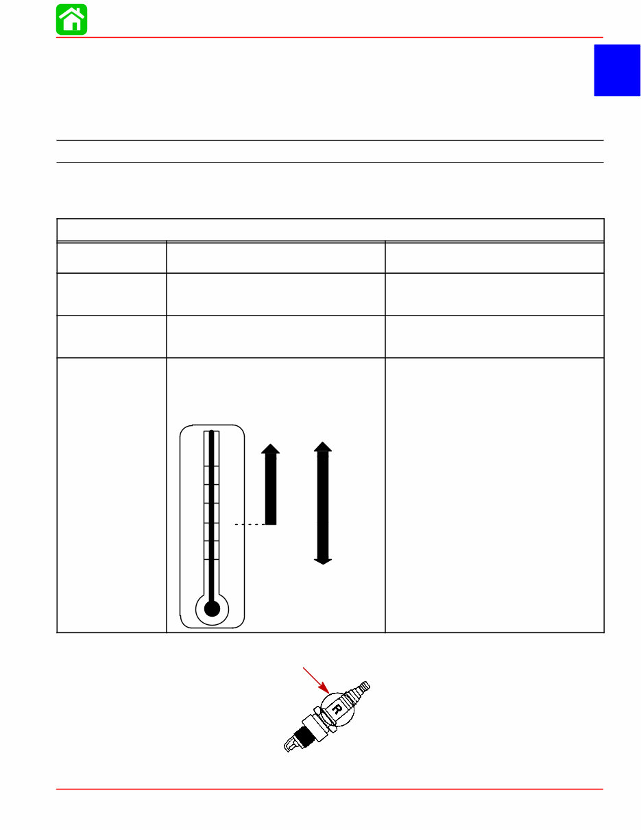
ENGINE OIL
+20
+40
+60
+80
F°
C°
0
+100
–7
+4
+16
+27
–18
+38
SAE
10W-30
SAE
25W-40
p/n 35-822626A2
p/n 91-802653
Either 3 Quarts or 3 Liters
SAE 10W-30 viscosity oil is recom-
mended for use in all temperatures.
SAE 25W-40 viscosity oil may be used at
temperatures above 40° F (4° C).
Use Quicksilver 4-Cycle Marine Oil with
the proper viscosity for the expected
temperature in your area (see range
thermometer on left). If not available, use
a premium quality 4-cycle engine oil, cer-
tified to meet or exceed anyone of the
following American Petroleum Institute
(API) service classifications SH, SG, SF,
CF-4, CE, CD, CDll.
IMPORTANT: Use resistive spark plugs only.

SPECIFICATIONS
Page 1A-2 90-857046 AUGUST 1998
IGNITION
SYSTEM
Readings taken @
68°F (20°C).
Type
Spark Plug:
Type
Gap
Hex Size
Firing Order
Ignition Timing:
@ Idle (800 rpm)
@ WOT (6000 rpm)
Charge Coil Resistance
Crank Position Sensor Resistance
Ignition Coil Resistance:
Primary
Secondary (W/o Boots)
ECM Engine Speed Limiter
Soft Reduction (Retards Timing)
Spark Cut-Out Reduction (Percent
ages of ignition spark are Cut-Out)
ECM Overheat/Low Oil Pressure
Speed Control
Engine Temperature Sensor
Capacitor Discharge Ignition
NGK DPR6EA-9
0.035 in. (1.0 mm)
18 mm
1-2-3
10° A.T.D.C
28° B.T.D.C
660 - 710 Ω (GRN/WHT - WHT/GRN)
300 - 350 Ω (RED - WHT)
0.08 - 0.7 Ω (BLK - BLK/WHT)
3.5 - 4.7 kΩ (BLK - High Tension)
6200 rpm
6250 rpm
Approximately 2000 rpm
See Graph Section 2A-Ignition
CHARGING
SYSTEM
Readings taken @
68°F (20°C).
Alternator Type:
6 Amp. Manual Lighting Coil Output
Lighting Coil Resistance
15 Amp. Electric Alternator Output
Battery Charging Coil Resistance
Power Bobbin Resistance
(For Electrothermal Valve)
Quicksilver Tachometer Setting
Single Phase (12 Pole)
6 Amps.
0.9 - 1.1 Ohms (YEL-YEL)
12.6 V-15 Amps. (185 Watts)
(Rectified/Regulated)
0.22 - 0.24 Ohms (YEL-YEL)
6.7-7.1 Ohms (YEL/BLK-YEL/BLK)
“6P” or “4”
STARTING
SYSTEM
Manual Start
Electric Start:
Starter Type
Output
Ampere Draw Under:
(Load)
(No Load)
Recoil Starter
Bendix
1.1 kW
106.0 Amps
21.1 Amps
BATTERY
Battery Rating
Minimum Requirement
For operation below 32° F (0° C)
465 Marine Cranking Amps (MCA)
or 350 Cold Cranking Amps (CCA)
1000 Marine Cranking Amps (MCA) or
775 Cold Cranking Amps (CCA)
ENRICHMENT
CONTROL
SYSTEM
Readings taken @
68°F (20°C).
Auto Enrichener Resistance
Electrothermal ram projection
15 - 25 Ohms (YEL/BLK - YEL/BLK)
0.3 in. (7 mm) after 5 min. of power
FUEL
SYSTEM
Fuel Pump Type
Fuel Pump:
Pressure
Plunger Stroke
Fuel Tank Capacity
External (Plunger/Diaphragm)
3-6 psi
0.23 - 0.38 in. (5.85 - 9.65 mm)
Accessory
SPECIFICATIONS
90-857046 AUGUST 1998 Page 1A-3
CARBURETOR
Idle rpm (Out Of Gear)
Idle rpm (In Forward Gear)
Wide Open Throttle rpm (WOT)
Range
Main Jet Size
Pilot Jet
Idle Jet
Float Height
900 ± 25 rpm
800 ± 25 rpm
5500–6000
#98
#38
#42
0.47-0.63 in. (12.0-16.0 mm)
CYLINDER
BLOCK
Type
Displacement
Number of Cylinders
4 Stroke Cycle – Over Head Camshaft
45.6 cu. in. (747cc)
3
STROKE Length 2.953 in. (75 mm)
CYLINDER
BORE
Diameter
Standard
Oversize-0.010 in. (0.25 mm)
Oversize-0.020 in. (0.50 mm)
Taper/Out of Round Maximum
Bore Type
2.5591 in. (65 mm)
2.5689 in. (65.25 mm)
2.5787 in. (65.5 mm)
0.003 in. (0.08 mm)
Cast Iron
PISTON
Piston Type
O.D. at Skirt
Standard
Oversize-0.010 in. (0.25 mm)
Oversize-0.020 in. (0.50 mm)
Aluminum
2.5570 - 2.5578 in. (64.950 - 64.965 mm)
2.5669 - 2.5675 in. (65.2 - 65.215 mm)
2.5768 - 2.5774 in. (65.450 - 65.465 mm)
PISTON
CLEARANCE
Piston to Cylinder Clearance 0.0014 - .0026 in. (0.035 - 0.065 mm)
RINGS
Ring End Gap (Installed)
Top
Middle
Bottom (Oil Ring)
Side Clearance:
Top
Middle
0.006 - 0.012 in. (0.15 - 0.03 mm)
0.012 - 0.020 in. (0.30 - 0.50 mm)
0.008 - 0.028 in. (0.20 - 0.70 mm)
0.0008 - 0.0024 in. (0.02 - 0.06 mm)
0.0008 - 0.0024 in. (0.02 - 0.06 mm)
COMPRESSION
RATIO
Compression Ratio
Cylinder Compression*
(Electric Models Only, Cold Engine @
W.O.T.)
9.8:1
180 -210 psi (Peak)
PISTON PIN Piston Pin Diameter 0.6285 - 0.6287 in. (15.965 - 15.970 mm)
CONNECTING
ROD
Oil Clearance (Big End)
Small End Inside Diameter
0.0008 - 0.0020 in. (0.020 - 0.052 mm)
0.6293 - 0.6298 in. (15.985 - 15.998 mm)
CRANKSHAFT
Main Bearing Clearance
Crankshaft Run-out
0.0005 - 0.0017 in. (0.012 - 0.044 mm)
0.0018 in. (0.046 mm)
*NOTE: Manual start models are equipped with compression relief mechanism which will
not allow compression testing.
SPECIFICATIONS
Page 1A-4 90-857046 AUGUST 1998
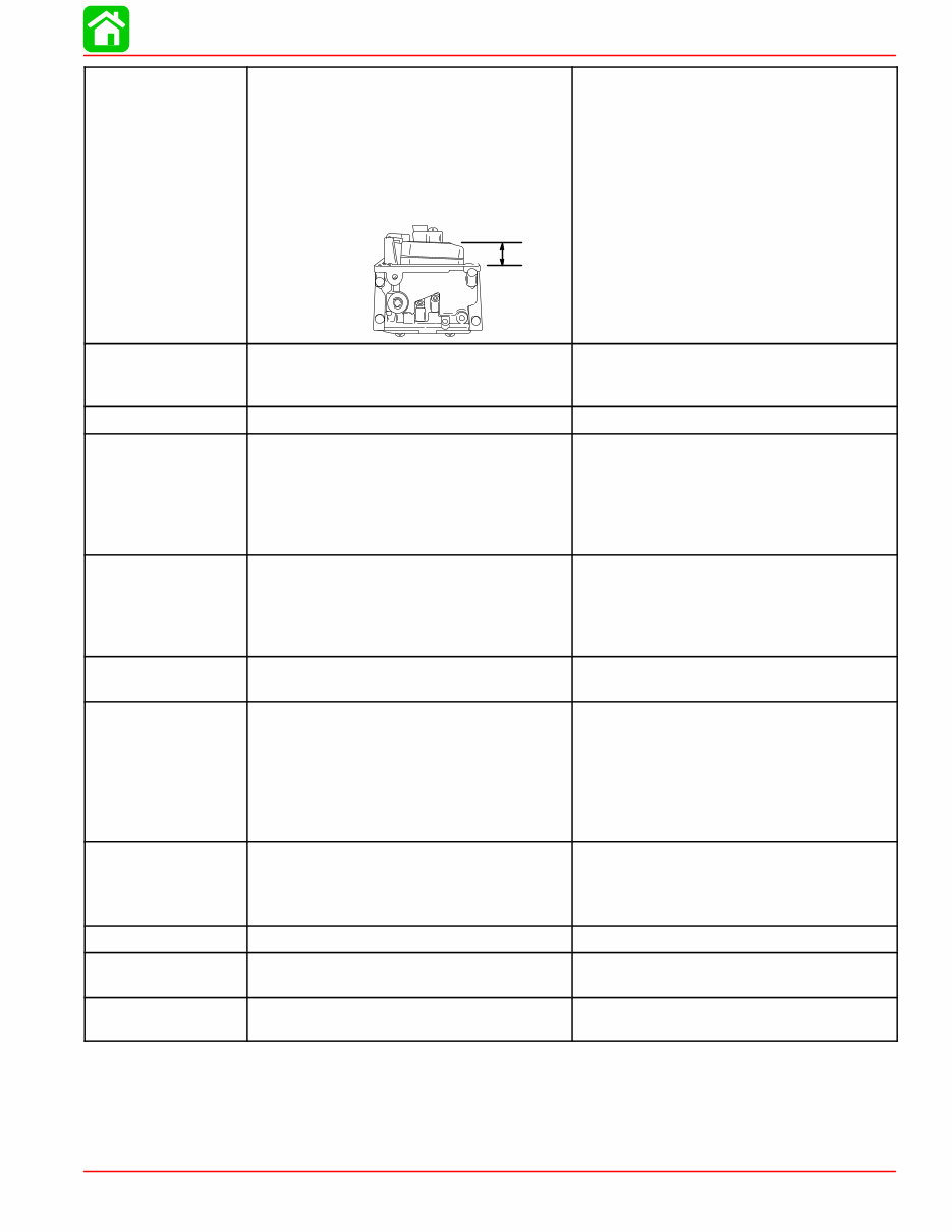
CAMSHAFT
Camshaft Dimensions
Intake “A”
Exhaust “A”
Intake “B”
Exhaust “B”
Run-out Limit
Camshaft Bearing Diameter “b”
A
B
b
b
b
b
1.216 - 1.220 in. (30.89 - 30.99 mm)
1.216 - 1.220 in. (30.89 - 30.99 mm)
1.022 - 1.025 in. (25.95 - 26.05 mm)
1.022 - 1.025 in. (25.95 - 26.05 mm)
0.0039 in. (0.1 mm)
1.4541 - 1.4549 in.
(36.935 - 36.955 mm)
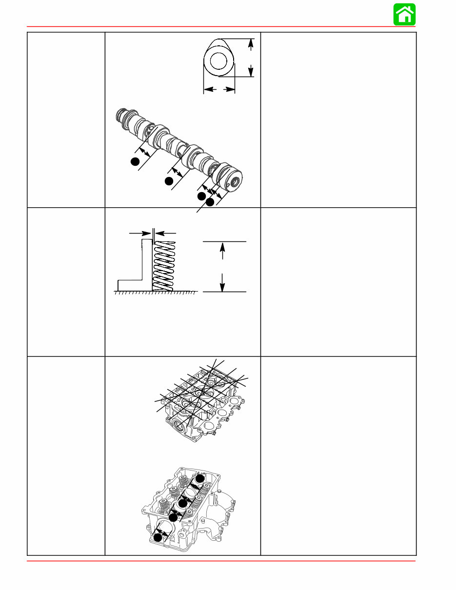
VALVE SPRING
Free Length “a”
Tilt Limit “b”
Compressed Pressure (Installed)
Intake
Exhaust
Tilt Limit (Intake & Exhaust)
Dir. of Winding (Intake & Exhaust)
a
b
1.491-1.569 in. (37.85-39.85 mm)
Less than 0.060 in. (1.7 mm)
19.8 - 22.0 lbs. (9.0 - 10.0 kg)
19.8 - 22.0 lbs. (9.0 - 10.0 kg)
0.043 in. (1.1 mm)
Left Hand
CYLINDER HEAD
Warp Limit
* Lines indicate
straight edge
measurement
Camshaft Bore Inside Diameter “a”
56900
a
a
a
a
56899
0.004 in. (0.1 mm)
1.4567 - 1.4577 in.
(37.000 - 37.025 mm)
SPECIFICATIONS
90-857046 AUGUST 1998 Page 1A-5
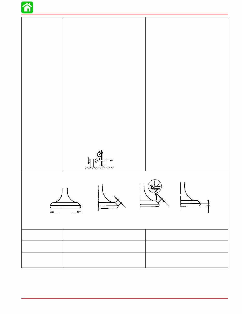
VALVES
Valve/Valve Seat/Valve Guides:
Valve Clearance (cold)
Intake
Exhaust
Valve Dimensions:
“A” Head Diameter
Intake
Exhaust
“B” Face Width
Intake
Exhaust
“C” Seat Width
Intake
Exhaust
“D” Margin Thickness
Intake
Exhaust
Stem Outside Diameter
Intake
Exhaust
Guide Inside Diameter
Intake
Exhaust
Stem To Guide Clearance
Intake
Exhaust
Stem Run-out Limit (max.)
0.006 - 0.010 in. (0.15 - 0.25 mm)
0.010 - 0.014 in. (0.25 - 0.35 mm)
1.256 - 1.264 in. (31.9 - 32.1 mm)
1.020 - 1.028 in. (25.9 - 26.1 mm)
0.079 - 0.124 in. (2.00 - 3.14 mm)
0.079 - 0.124 in. (2.00 - 3.14 mm)
0.035 - 0.043 in. (0.9 - 1.1 mm)
0.035 - 0.043 in. (0.9 - 1.1 mm)
0.020 - 0.035 in. (0.5 - 0.9 mm)
0.020 - 0.035 in. (0.5 - 0.9 mm)
0.2156 - 0.2161 in. (5.475 - 5.490 mm)
0.2150 - 0.2156 in. (5.460 - 5.475 mm)
0.2165 - 0.2170 in. (5.500 - 5.512 mm)
0.2165 - 0.2170 in. (5.500 - 5.512 mm)
0.0004 - 0.0015 in. (0.010 - 0.037 mm)
0.0010 - 0.0020 in. (0.025 - 0.052 mm)
0.0006 in. (0.016 mm)
“A”
“B”
“C”
“D”
Valve Dimensions
Head Diameter Face Width Seat Width Margin Thickness
ROCKER SHAFT
Outside Diameter 0.6288 - 0.6296 in.
(15.971 - 15.991 mm)
ROCKER ARM
Inside Diameter of Bore 0.6299 - 0.6306
(16.000 - 16.018 mm)
THERMOSTAT
Valve Opening Temperature
Full Open Temperature
Valve Lift (Minimum)
136° F - 143° F (58° C - 62° C)
158° F (70° C)
0.12 in. (3 mm)
You're Reading a Preview
What's Included?
Fast Download Speeds
Offline Viewing
Access Contents & Bookmarks
Full Search Facility
Print one or all pages of your manual
$27.99
$36.99
Viewed 32 Times Today


Secure transaction
What's Included?
Fast Download Speeds
Offline Viewing
Access Contents & Bookmarks
Full Search Facility
Print one or all pages of your manual
$27.99
$36.99
The Mercury Mariner 30HP 40HP Service Manual for Fourstroke engines, published in 1998, is an essential resource for both professional mechanics and DIY enthusiasts. This comprehensive manual provides detailed technical information and step-by-step procedures for maintenance, repair, and troubleshooting of the 30HP and 40HP Fourstroke engines.
Whether you are looking to perform routine maintenance or tackle more complex repairs, this manual offers valuable insights into the inner workings of the Mercury Mariner engines. With clear and concise instructions, it enables users to effectively service and maintain their outboard motors, ensuring optimal performance and longevity.


