! 90-44477--1 1192 Notice Throughout this publication, “Dangers”, “Warnings” and “Cautions” (accompanied by the International HAZARD Symbol ) are used to alert the mechanic to special in- structions concerning a particular service or operation that may be hazardous if performed incorrectly or carelessly. OBSERVE THEM CAREFULLY! These “Safety Alerts” alone cannot eliminate the hazards that they signal. Strict compliance to these special instruc- tions when performing the service, plus “Common Sense” operation, are major accident prevention measures. ! DANGER DANGER - Immediate hazards which WILL result in se- vere personal injury or death. ! WARNING WARNING - Hazards or unsafe practices which COULD result in severe personal injury or death. ! CAUTION Hazards or unsafe practices which could result in mi- nor personal injury or product or property damage. Notice to Users of This Manual This service manual has been written and published by the service department of Mercury Marine to aid our dealers’ mechanics and company service personnel when servic- ing the products described herein. It is assumed that these personnel are familiar with the servicing procedures of these products, or like or similar products manufactured and marketed by Mercury Marine, that they have been trained ing the recommended servic- ing procedures of these products which includes the use of mechanics’ common hand tools and the special Mercury Marine or recommended tools from other suppliers. We could not possibly know of and advise the service trade of all conceivable procedures by which a service might be performed and of the possible hazards and/or results of each method. We have not undertaken any such wide eval- uation. Therefore, anyone who uses a service procedure and/or tool, which is not recommended by the manufactur- er, first must completely satisfy himself that neither his nor the products safety will be endangered by the service pro- cedure selected. All information, illustrations and specifications contained in this manual are based on the latest product information available at the time of publication. As required, revisions to this manual will be sent to all dealers contracted by us to sell and/or service these products. It should be kept in mind, while working on the product, that the electrical system and ignition system is capable of vio- lent and damaging short circuits or severe electrical shocks. When performing any work where electrical termi- nals could possibly be grounded or touched by the me- chanic, the battery cables should be disconnected at the battery. Any time the intake or exhaust openings are exposed dur- ing service they should be covered to protect against acci- dental entrance of foreign material which could enter the cylinders and cause extensive internal damage when the engine is started. It is important to note, during any maintenance procedure replacement fasteners must have the same measure- ments and strength as those removed. Numbers on the heads of the metric bolts and on the surfaces of metric nuts indicate their strength. Customary bolts use radial lines for this purpose, while most customary nuts do not have strength markings. Mismatched or incorrect fasteners can result in damage or malfunction, or possibly personal inju- ry. Therefore, fasteners removed should be saved for re- use in the same locations whenever possible. Where the fasteners are not satisfactory for re-use, care should be taken to select a replacement that matches the original.
90-44477--1 1192 Cleanliness and Care of Outboard Motor A marine power product is a combination of many ma- chined, honed, polished and lapped surfaces with toler- ances that are measured in the ten thousands of an inch. When any product component is serviced, care and clean- liness are important. Throughout this manual, it should be understood that proper cleaning, and protection of ma- chined surfaces and friction areas is a part of the repair pro- cedure. This is considered standard shop practice even if not specifically stated. Whenever components are removed for service, they should be retained in order. At the time of installation, they should be installed in the same locations and with the same mating surfaces as when removed. Before raising or removing and outboard engine from a boat, the following precautions should be adhered to: (1) Check that flywheel is secured to end of crankshaft with a locknut and lifting eye is threaded into flywheel a mini- mum of 5 turns. (2) Connect a hoist of suitable strength to the lifting eye. In addition, personnel should not work on or under an out- board which is suspended. Outboards should be attached to work stands, or lowered to ground as soon as possible. We reserve the right to make changes to this manual with- out prior notification. Refer to dealer service bulletins for other pertinent informa- tion concerning the products described in this manual. Service Manual Outline Section 1 - General Information & Specifications Section 2 - Electrical & Ignition Section 3 - Fuel System & Carburetion Section 4 - Powerhead Section 5 - Mid-Section Section 5A - Gear Housing (Non-Shifting) Section 5B - Gear Housing (Shiftable-F/N) Section 6 - Rewind Starter Assembly
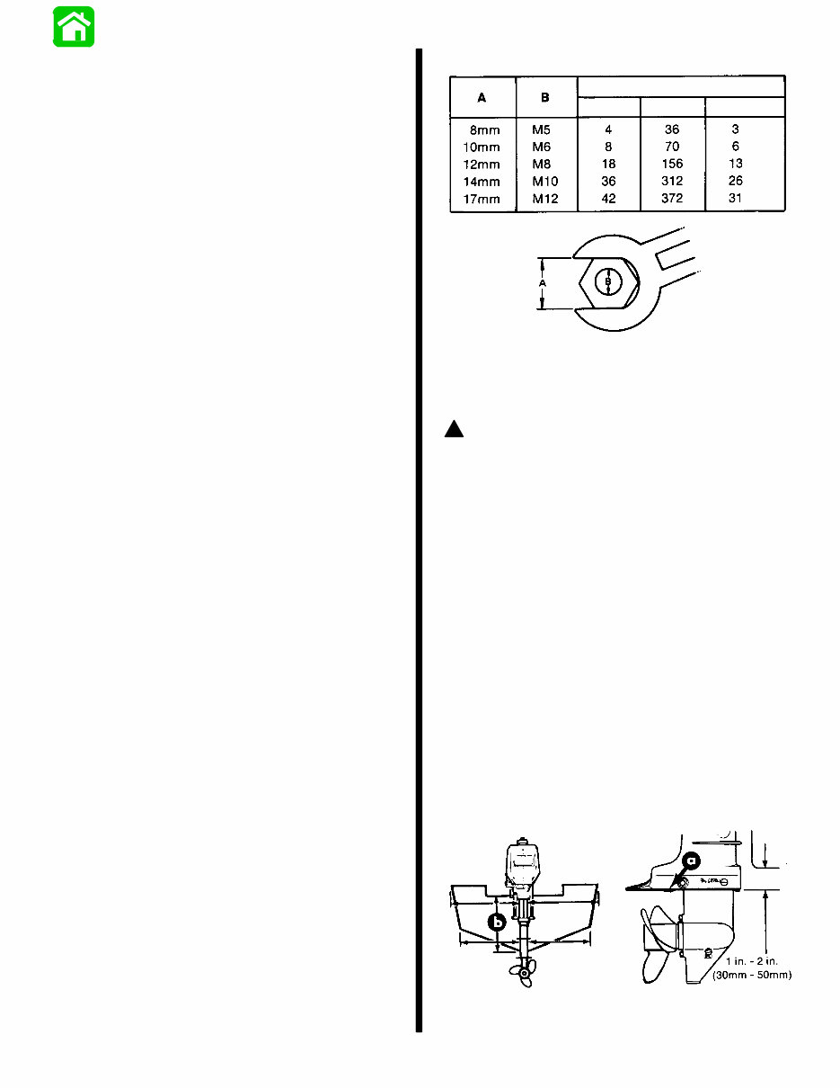
GENERAL INFORMATION and SPECIFICATIONS - 1-3 90-44477--1 1192 Gear Housing Gear Ratio (Model 2.2) 1.85:1 . . . . . . . . . . . . . . . . . . . . . . Gear Ratio (Models 2.5/3.0/ 3.3) 2.18:1 . . . . . . . . . . . . . Gear Type Spiral Bevel . . . . . . . . . . . . . . . . . . . . . . . . . . . . Clutch Type Sliding Dog . . . . . . . . . . . . . . . . . . . . . . . . . . Propeller Drive System Drive (Shear) Pin . . . . . . . . . . . . . Lubricant Type Quicksilver Gear Lube . . . . . . . . . . . . . . . . . . . Capacity 3 oz. (90ml) . . . . . . . . . . . . . . . . . . . . . . . . . . Mid-Section Steering Angle 360° . . . . . . . . . . . . . . . . . . . . . . . . . . . . . Tilt Pin Positions 4 . . . . . . . . . . . . . . . . . . . . . . . . . . . . . . . Full Tilt-Up Angle 75° . . . . . . . . . . . . . . . . . . . . . . . . . . . . . . Allowable Transom Thickness 1.18 in. - 2.165 in. . . . . . (30mm - 55mm) Torque Specifications 1. All torque values are for clean, dry, corrosion free threads, except where locking compounds are speci- fied. Refer to appropriate section of this manual. 2. Cover and housing screws MUST BE torqued by tight- ening in 3 progressive steps (following specified torque sequence) until specified torque is reached. Refer to appropriate section of this manual. 3. When retightening powerhead and gear housing mounting bolts, first back them out one turn, and then retorque to specification. 4. To retighten spark plug, start engine and warm-up to operating temperature. Stop engine and allow to cool, then retorque plug to specification. 5. Propeller MUST BE secured with cotter pin. Powerhead Flywheel Nut 30 lb. ft. (4.1 N·m) . . . . . . . . . . . . . . . . . . . . . Crankcase Cover to Cylinder Block Bolts 50 lb. in. (5.6 N·m) . . . . . . . . . . . . Cylinder Head Bolts 85 lb. in. (9.6 N·m) . . . . . . . . . . . . . . . Spark Plug 20 lb. ft. (27.1 N·m) . . . . . . . . . . . . . . . . . . . . . . STANDARD BOLTS AND NUTS TORQUE SPECIFICATION N·M LB. FT. LB. IN. Outboard Installation ! WARNING DO NOT OVERPOWER - Most boats are rated and certi- fied for the maximum horsepower capabilities of the boat. Refer to the boat “Certification Plate” for the maximum horsepower limit. If in doubt, contact your dealer. Transom Height 1. This outboard is designed to provide optimum per- formance when mounted at the recommended tran- som height. If the transom is too high, the propeller may operate too close to the water surface introducing air over the propeller blades, causing a lost of thrust (particularly when attempting to plane off or during a turn). If the transom is too low, a performance loss is created by excessive lower unit drag and water spray (additionally, under clearance may also present a problem). 2. Conventional installations generally locate the gear housing anti-ventilation plate parallel to and approxi- mately 1 in. - 2 in. (30mm - 50mm) below the boat bot- tom. 50649 a - Anti-Ventilation Plate b - Recommended Boat Transom Height - 15 in. (381mm)
1-4 - GENERAL INFORMATION and SPECIFICATIONS 90-44477--1 1192 Mounting Outboard on Transom ! WARNING Before operating the outboard, it MUST BE PROPERLY SECURED to the boat transom. Failure to adhere to the outboard mounting instructions, following, may result in loss of the outboard, damage to boat and/or out- board and injury to occupants of the boat. 1. Center outboard on boat transom at recommended transom height (see “Transom Height,” preceding) and secure outboard to transom with clamp screws. To avoid damage to transom and to prevent clamp screws from working loose during operation, make certain that clamp screws are tightened securely and equally. Clamp screws should be checked for tightness periodi- cally. IMPORTANT: During use, a periodic check of the clamp screws is recommended to ensure that the outboard remains secure on the transom. Fuel Recommendations Gasoline Recommendations ! WARNING Use CARE when transporting fuel container, whether in a boat or car. DO NOT fill fuel container to maximum capacity. Gasoline will expand considerably as it warms up and can build up pressure in the fuel con- tainer. This can cause fuel leakage and a potential fire hazzard. Any gasoline that will satisfactorily operate an automobile engine is suitable for your outboard motor. IMPORTANT: While the use of REGULAR LEADED gas- oline is entirely satisfactory, LEAD FREE or LOW LEAD regular gasolines are PREFERRED as they gen- erally provide an “extra margin” of spark plug life. Some fuel distributors pre-mix gasoline and oil for 2-cycle engines. Such fuels, if known to be of of recommended quality, are acceptable. If in doubt, check with your local dealer. ! CAUTION DO NOT USE white gasolines or fuels intended for stoves and lanterns. Use of improper gasolines and/or oils can cause serious damage to your outboard mo- tor. Oil Recommendations Mix recommended gasoline with Quicksilver 2-Cycle Out- board Oil in ratio shown in the following chart. If Quicksilver 2-Cycle Oil is not available, substitute a high quality 2-cycle oil intended for outboard use and meets NMMA rating TC- WII, as shown on oil container. NMMA rating TC-WII is the Boating Industry Association’s designation for ap- proved, 2-cycle water-cooled outboard oils. Use at oil man- ufacturer’s recommended gasoline-oil mixture as shown on the label. (NOT TO EXCEED 50:1 RATIO.) ! CAUTION The use of other than recommended gasoline and Quicksilver 2-Cycle Outboard Oil or an acceptable oil may cause piston scoring, bearing failure or both. DO NOT, under any circumstances, use multi-grade or oth- er highly detergent automobile oils or oils which con- tain metallic additives. IMPORTANT: When checking fuel level and/or filling the motor fuel tank ALWAYS check the fuel tank cap to verify that the seal is properly seated inside the cap. Tighten fuel tank cap securely. FUEL MIXTURE Use a 50:1 gasoline-oil ratio for “break-in” and all normal operation of your outboard motor. (See chart, following.) U.S. Measure Imperial Measure Metric Measure Quicksilver 2-Cycle Oil 16 U.S. oz. to each 6 gallons of gasoline 15 Imp. oz. to each 5 Imp. gallons gasoline 400cc to each 20 liters of gasoline Other Acceptable Oils Use at manufacturer’s recommended gasoline/oil ratio, not to exceed 50:1 IMPORTANT: Using less than the recommended pro- portion of oil may result in very serious damage from lack of sufficient lubrication. Using more than the rec- ommendations will cause spark plug fouling, erratic carburetion, excessive smoking and faster-than-nor- mal carbon accumulation. Correct Fuel Mixing Procedure ! WARNING Observe fire prevention rules, particularly the matter of smoking. Mix fuel outdoors or in a well-ventilated lo- cation.
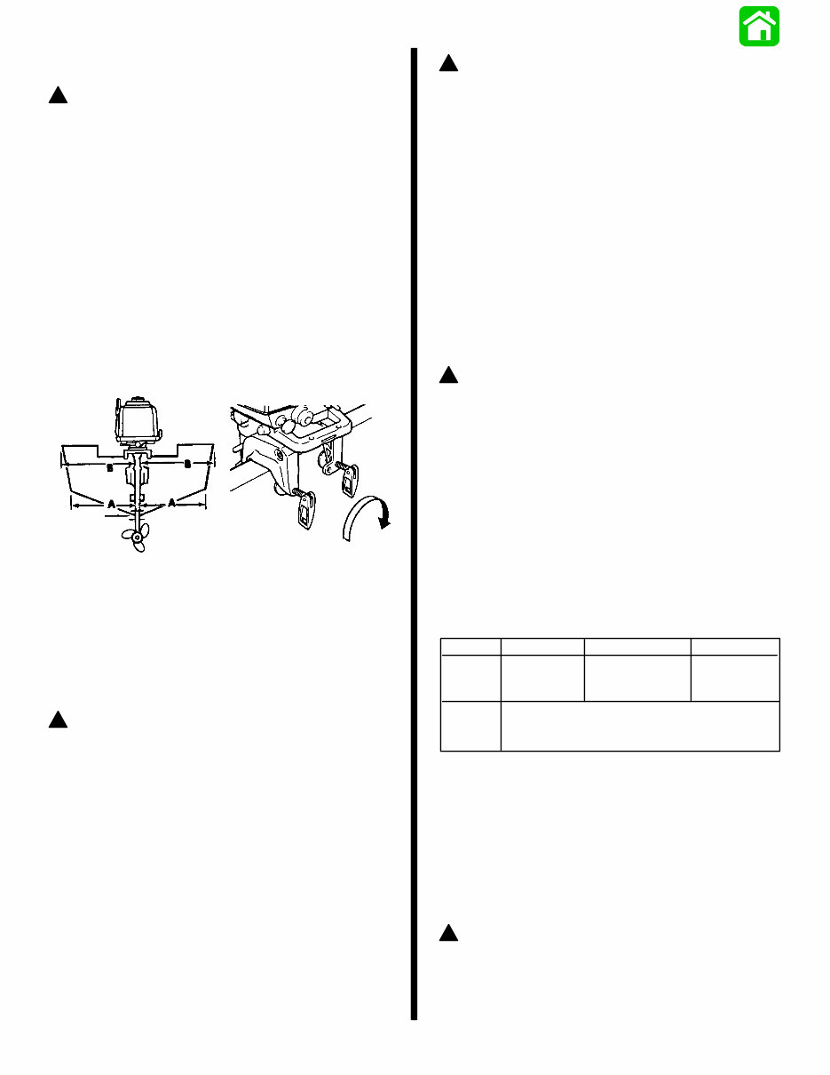
GENERAL INFORMATION and SPECIFICATIONS - 1-5 90-44477--1 1192 Mix fuel in a separate container . Measure accurately the required amounts of oil and gasoline. Pour a small amount of gasoline into container and add a small amount of oil (about the same amount as gasoline). Mix thoroughly by shaking or stirring vigorously; then add balance of oil and gasoline, mix again and pour into fuel tank. Cleanliness is important in mixing fuel. Be consistent; prepare each batch of fuel exactly the same as previous amounts (to avoid readjustment of carburetor low speed mixture screw). IMPORTANT: Always use fresh gasoline. Gasoline forms gum and varnish deposits and when kept in a tank for a length of time, may cause trouble. ! WARNING Use care to prevent spilling fuel when filling the motor fuel tank. DO NOT OVERFILL. If tank is overfilled, fuel may spill into the cowling and if gasoline vapors are present, an errant spark could cause an explosion or fire. If fuel is spilled, remove cowling and clean up as much of the spill as possible. Allow a minimum of 5 minutes for ventilation/evaporation of fuel and/or vapors BE- FORE ATTEMPTING TO START ENGINE. Tilt Angle Adjustment The angle of the motor can be adjusted by changing the po- sition of the tilt angle adjustment pin in the holes provided in the clamp brackets. 50652 a - Tilt Angle Adjustment Pin Adjusting Tilt Angle of the Motor - 2.5/3.0 Model 2.2/3.3 - Reposition tilt screw/nut as in (a) above. The angle of the motor is important for obtaining the best performance of the motor. The tilt angle should be adjusted so that the motor anti-ventilation plate is parallel to the wa- ter surface when at full speed. Wrong! Bow Up Wrong! Bow Down Right! Plane or Even Keel Outboard Motor Angle Positions Adjustments and Maintenance ! WARNING DO NOT attempt to remove or install cowl while engine is running. Cowl Removal and Installation MODEL 2.2 Remove spark plug access cover. Remove 10 screws to remove cowling. Replace 10 screws and access cover to reinstall cowl. MODELS 2.5/3.0 (1990)
The Mercury Mariner 3.3 HP 2-stroke Factory Service Repair Manual is a comprehensive resource for repairing and adjusting the Mercury Mariner 3.3 HP 2-stroke engine. It serves as a valuable reference for both professional mechanics and DIY enthusiasts, offering detailed explanations of installation, removal, disassembly, assembly, repair, and check procedures in a clear and sequential manner.
This manual is known by various names, including:
Mercury Mariner 3.3 HP 2-stroke service manual
Mercury Mariner 3.3 HP 2-stroke repair manual
Mercury Mariner 3.3 HP 2-stroke workshop manual
Mercury Mariner 3.3 HP 2-stroke shop manual
Rest assured, all the above manuals are one and the same.
Upon purchase, you will have immediate access to the manual, which is conveniently divided into chapters. The manual index provides an overview of the content:
General information & specifications
Electrical & ignition
Fuel system & carburetion
Powerhead
Mid-section
Gear housing (non-shifting)
Gear housing (shiftable F/N)
Rewind starter assembly
Each chapter is further divided into sections, with subsections featuring smaller print titles. Additionally, exploded diagrams are included at the beginning of each removal and disassembly section to aid in part identification and procedure clarification. The manual is available in PDF format, allowing for easy printing of specific pages or the entire manual as needed.
Recently Viewed
5,521,897Happy Clients
2,594,462eManuals
1,120,453Trusted Sellers
15Years in Business
Price:
Actual Price:
Mercury Mariner 3.3 HP 2-stroke Factory Service Repair Manual