Mercury Mariner 20 HP Outboard Workshop Service Manual
What's Included?
Lifetime Access
Fast Download Speeds
Online & Offline Access
Access PDF Contents & Bookmarks
Full Search Facility
Print one or all pages of your manual
MODELS United States 0G044027 and Above . . . . . . . Belgium 09807909 and Above . . . . . . . . . . . With Serial Numbers SERVICE MANUAL 20 JET S 20 S 25 Mercury/Mariner 25 MARATHON S 25 SEAPRO Printed in U.S.A. 1998, Mercury Marine 90-826883R2 JUNE 1998
90-826883R2 JUNE 1998 Page i Notice Throughout this publication, “Dangers”, “Warnings” and “Cautions” (accompanied by the In- ternational HAZARD Symbol ) are used to alert the mechanic to special instructions con- cerning a particular service or operation that may be hazardous if performed incorrectly or carelessly. OBSERVE THEM CAREFULLY! These “Safety Alerts” alone cannot eliminate the hazards that they signal. Strict compliance to these special instructions when performing the service, plus “Common Sense” operation, are major accident prevention measures. DANGER DANGER - Immediate hazards which WILL result in severe personal injury or death. WARNING WARNING - Hazards or unsafe practices which COULD result in severe personal in- jury or death. CAUTION Hazards or unsafe practices which could result in minor personal injury or product or property damage. Notice to Users of This Manual This service manual has been written and published by the Service Department of Mercury Marine to aid our dealers’ mechanics and company service personnel when servicing the products described herein. It is assumed that these personnel are familiar with the servicing procedures of these prod- ucts, or like or similar products manufactured and marketed by Mercury Marine, that they have been trained in the recommended servicing procedures of these products which in- cludes the use of mechanics’ common hand tools and the special Mercury Marine or recom- mended tools from other suppliers. We could not possibly know of and advise the service trade of all conceivable procedures by which a service might be performed and of the possible hazards and/or results of each method. We have not undertaken any such wide evaluation. Therefore, anyone who uses a service procedure and/or tool, which is not recommended by the manufacturer, first must completely satisfy himself that neither his nor the products safety will be endangered by the service procedure selected. All information, illustrations and specifications contained in this manual are based on the latest product information available at the time of publication. As required, revisions to this manual will be sent to all dealers contracted by us to sell and/or service these products. It should be kept in mind, while working on the product, that the electrical system and ignition system are capable of violent and damaging short circuits or severe electrical shocks. When performing any work where electrical terminals could possibly be grounded or touched by the mechanic, the battery cables should be disconnected at the battery. Any time the intake or exhaust openings are exposed during service they should be covered to protect against accidental entrance of foreign material which could enter the cylinders and cause extensive internal damage when the engine is started.
Page ii 90-826883R2 JUNE 1998 It is important to note, during any maintenance procedure replacement fasteners must have the same measurements and strength as those removed. Numbers on the heads of the met- ric bolts and on the surfaces of metric nuts indicate their strength. American bolts use radial lines for this purpose, while most American nuts do not have strength markings. Mis- matched or incorrect fasteners can result in damage or malfunction, or possibly personal injury. Therefore, fasteners removed should be saved for reuse in the same locations when- ever possible. Where the fasteners are not satisfactory for re-use, care should be taken to select a replacement that matches the original. Cleanliness and Care of Outboard Motor A marine power product is a combination of many machined, honed, polished and lapped surfaces with tolerances that are measured in the ten thousands of an inch/mm. When any product component is serviced, care and cleanliness are important. Throughout this manu- al, it should be understood that proper cleaning, and protection of machined surfaces and friction areas is a part of the repair procedure. This is considered standard shop practice even if not specifically stated. Whenever components are removed for service, they should be retained in order. At the time of installation, they should be installed in the same locations and with the same mating surfaces as when removed. Personnel should not work on or under an outboard which is suspended. Outboards should be attached to work stands, or lowered to ground as soon as possible. We reserve the right to make changes to this manual without prior notification. Refer to dealer service bulletins for other pertinent information concerning the products de- scribed in this manual. Page Numbering Two number groups appear at the bottom of each page. The example below is self-explana- tory. EXAMPLE: 90-826883 R2 JUNE 1998 6A-7 Revision No. 2 Month of Printing Year of Printing Section Number Part of Section Letter Page Number
1 2 3 4 5 6 7 8 9 Important Information Electrical Fuel System Powerhead Mid-Section Lower Unit Attachment/Control Linkage Manual Starter 90-826883R2 JUNE 1998 Page iii Service Manual Outline Section 1 - Important Information A - Specifications B - Maintenance C - General Information D - Outboard Installation Section 2 - Electrical A - Ignition B - Charging & Starting System C - Timing, Synchronizing & Adjusting D - Wiring Diagrams Section 3 - Fuel System A - Carburetor/Fuel Pump B - Emissions Section 4 - Powerhead Section 5 - Mid-Section Section 6 - Lower Unit A - Gear Housing B - Jet Drive Section 7 - Attachments/Control Linkage A - Throttle/Shift Linkage B - Tiller Handle C - Side Shift Section 8 - Manual Starter
1 A SPECIFICATIONS 90-826883R2 JUNE 1998 Page 1A-1 IMPORTANT INFORMATION Section 1A - Specifications Table of Contents Master Specifications 1A-2 . . . . . . . . . . . . . . . . . . . . . . . . .
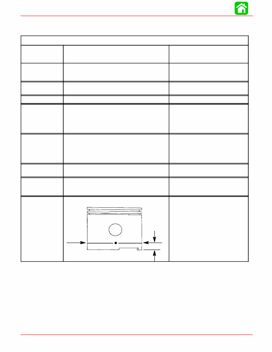
SPECIFICATIONS Page 1A-2 90-826883R2 JUNE 1998 Master Specifications Model 15XD/20 Jet /20/25 HORSEPOWER (KW) Model 20 Jet Model 20 Model 25 20 (14.9) 20 (14.9 25 (18.7) OUTBOARD WEIGHT 15 in. (38 cm) 20 in. (51 cm) 20 Jet 114 lbs - 52 kg 117 lbs - 53 kg 124 lbs - 56 kg CYLINDER BLOCK Type Displacement Two Cylinder - Two Cycle 24.4 cu. in. (400 cc) STROKE Length 2.362 in. (60 mm) CYLINDER BORE Diameter (Standard) Taper/Out of Round Maximum* Bore Type: S/N 0G202749 and Below S/N 0G202750 and Above 2.562 in. (65.01 mm) 0.003 in. (0.08 mm)* Chrome Mercosil CRANK SHAFT Top Main Bearing Journal Center Main Bearing Journal Bottom Main Bearing Journal Connecting Rod Journal End Play 1.251 in. (31.77 mm) 1.000 in. (25.40 mm) 1.125 in. (28.58 mm) 0.883 in. (22.43 mm) 0.004-0.019 (0.10-0.64 mm) CONNECTING ROD Piston Pin End (I.D.) Crankpin End (I.D.) 0.897 in. (22.78 mm) 1.196 in. (30.38 mm) PISTON Piston Type O.D. at Skirt (Standard) Ring End Gap Aluminum 2.5583 - 2.5593 (64.98 - 65.00) 0.011-0.025 (.28 mm - .64 mm) PISTON DIA. Dimension “A” at Right Angle (90°) to Pis- ton Pin 0.50 in. (12.7 mm) 2.5583 in. ± .0005 in. (64.98 mm ± .0127 mm)Using a micrometer, measure dimension “A” at location shown. Dimension “A” should be 2.5583 in. ± .0005 for a STANDARD size piston (new) Di- mension “A” will be 0.001 – 0.0015 less if coating is worn off piston (used) *Models S/N 0G202749 and Below: NOTE: The cylinder bores are chrome and cannot be be rebored or efficiently honed. Check each cylinder bore for an out-of-round “egg shaped” cylinder. A maximum of 0.003 in. (0076mm) is allowable. *Models S/N 0G202750 and Above: NOTE: The cylinder block is Mercosil and the cylinders can be rebored to 0.030 in. over- sized. Check each cylinder bore for an out-of-round “egg shaped” cylinder. A maximum of 0.003 in. (0.076mm) is allowed.
SPECIFICATIONS 90-826883R2 JUNE 1998 Page 1A-3 Master Specifications GEAR HOUSING Forward - Neutral - Reverse Gear Ratio Gearcase Capacity Lubricant Type Forward Gear - No. of Teeth-Type Pinion Gear - No. of Teeth-Type Pinion Foreword Gear Backlash Reverse Gear Backlash Water Pressure @ RPM Water Pressure With 120° Thermostat Full Shift 2.25:1 8.8 fl.oz. (260 ml) Quicksilver Gear Lube Premium Blend 27 12 Not Adjustable Not Adjustable Not Adjustable 2-7 PSI @ 2000 RPM 0-6 PSI (SPORADIC) 2000 RPM MID SECTION Transom Height - Short Shaft - Long Shaft 15 in. (38 cm) 20 in. (51 cm) FUEL SYSTEM Fuel Pump Type Recommended Gasoline Fuel Tank Capacity Operating Fuel/Oil Ratio Integral Automotive Unleaded with a Minimum Pump Posted Octane Rating of 87 6.6 U.S. Gallons 50:1 OIL Recommended Oil (Pre-Mix @ 50:1) NMMA TC-W II or TC-W III 2-Cycle Outboard Oil STARTING SYSTEM Manual Start Rope Length Electric Start Ampere Draw (cranking) Recoil 66 in. (1676 mm) 12 Volt 55 amperes CHARGING SYSTEM Alternator Output BLACK Stator - 2 Magnet Flywheel (8 Pole)(4 Pulses) RED Stator - 4 Magnet Flywheel (10 Pole)(5 Pulses) 4 Amp. (48 Watt) @ 6000 RPM 6 amp (72 Watt) @ 6000 RPM BATTERY Battery Rating 465 Marine Cranking Amps (MCA) or 350 Cold Cranking Amps (CCA)
SPECIFICATIONS Page 1A-4 90-826883R2 JUNE 1998 IGNITION SYSTEM Readings taken @ 68°F (20°C). Type Spark Plug Type (NGK) Spark Plug Gap Spark Plug Hex Firing Order 20 Jet 1994 1 / 2 THRU 1998 20/25 1994 1 / 2 THRU 1996 Electronic Spark Advance Idle @ 750 ± 50 RPM (In Forward Gear) Fast Idle Speed Maximum BTDC (Running) Setup Timing Stator High Speed Winding Stator Low Speed Winding Diode Test Ignition Coil Resistance: Primary Secondary (w/o Boots) 20 Jet 1999 and Newer 20/25 1997/98 Models Mechanical Spark Advance Idle @ 750 ± 50 RPM (In Forward Gear) Fast Idle Speed Maximum BTDC (Running) Stator High Speed Winding Stator Low Speed Winding Diode Test Ignition Coil Resistance: Primary Secondary (w/o Boots) Trigger Capacitor Discharge Ignition NGK BP8H-N-10 0.040 in. (1.0 mm) 18 mm 1-2 4°± 2° B.T.D.C (Not Adjustable) 1400 RPM ± 250 RPM 25°± 1 @5500 RPM 28° B.T.D.C. @ 3000 ± 200 R.P.M. (Set-up timing of 28° B.T.D.C. will be retarded to 25° B.T.D.C. @ 5500 R.P.M.) 100 – 180 Ω (RED – BLK) 2900 – 3500 Ω (BLUE – BLACK) 2800 – 3400 Ω (RED – BLUE) 0 Ω 850 – 1200 Ω 6°± 1° B.T.D.C 1500 RPM ± 200 RPM 25°± 1 @5500 RPM 120 - 180 Ω (BLK/WHT - GRD) 3200 - 3800 Ω (BLK/YEL - GRD) 3100 – 3700 Ω (BLK/YEL - BLK/ WHT) 0.02 - 0.04 Ω 8000 - 11000 Ω 6500 - 8500 Ω JET DRIVE Impeller Liner Clearance 0.030 in. (0.8 mm) * Use NGK BPZ8H-N-10 Where Radio Frequency Interference (RFI) Suppression is Required.
SPECIFICATIONS 90-826883R2 JUNE 1998 Page 1A-5 Master Specifications CARBURETOR SPECIFI- CATIONS Idle RPM (In Forward Gear) Wide Open Throttle (WOT) RPM 20 25 Idle Mixture Screw Adjustment (Preset-Turns Out) 20 20 Jet 25/25 Seapro/25 Marathon Float Level Main Jet Size 1994 1 / 2 thru 1996 -20 (WMC-44) -25/20 Jet (WMC-45) -25 Seapro/Marathon (WMC-46) -25 Seapro/Marathon (WMC-46A) 1997 and Newer -20 Jet (WMC-45) -20 (WMC-52) -25 (WMC-53) -25 Seapro/Marathon (WMC-54) 750 ± 50 4500 - 5500 5000 - 6000 1 ± 1/4 Turn 1-1/2 ± 1/2 Turn 1-1/4 ± 1/4 Turn 1.0 in. (25.4 mm) 0.044 in. (1.12 mm) 0.076 in. (1.93 mm) 0.076 in. (1.93 mm) 0.080 in. (2.03 mm) 0.076 in. (1.93 mm) 0.044 in. (1.12 mm) 0.076 in. (1.93 mm) 0.080 in. (2.03 mm) TIMING SPECIFI- CATIONS 20 Jet 1994 1 / 2 THRU 1998 20/25 1994 1 / 2 THRU 1996 Electronic Spark Advance Idle @ 750 ± 50 RPM (In Forward Gear) Fast Idle Speed Maximum BTDC (Running) Setup Timing 20/25 1997 AND NEWER 20 Jet 1999 AND NEWER Mechanical Spark Advance Idle @ 750 ± 50 RPM (In Forward Gear) Fast Idle Speed Maximum BTDC (Running) 4°± 2° B.T.D.C (Not Adjustable) 1400 RPM ± 250 RPM 25°± 1 @5500 RPM 28° B.T.D.C. @ 3000 ± 200 R.P.M. (Set-up timing of 28° B.T.D.C. will be retarded to 25° B.T.D.C. @ 5500 R.P.M.) 6°± 1° B.T.D.C 1500 RPM ± 200 RPM 25°± 1 @5500 RPM
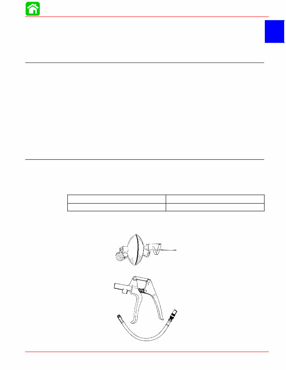
1 B MAINTENANCE 90-826883R2 JUNE 1998 Page 1B-1 IMPORTANT INFORMATION Section 1B - Maintenance Table of Contents Table of Contents 1B-1 ............................ Specifications 1B-1 ............................... Gear Case Lubricant Capacity 1B-1 .............. Special Tools 1B-1 ............................. Quicksilver Lubricant/Sealant 1B-2 ............... Inspection and Maintenance Schedule 1B-3 .......... Before Each Use 1B-3 ......................... After Each Use 1B-3 ........................... Every 100 Hours of Use or Once Yearly, Whichever Occurs First 1B-3 .................... Every 300 Hours of Use or Three Years 1B-3 ...... Flushing The Cooling System 1B-4 ................. Fuel System 1B-5 ................................ Fuel Line Inspection 1B-5 ....................... Engine Fuel Filter 1B-5 ......................... Corrosion Control Anode 1B-6 ..................... Spark Plug Inspection 1B-7 ........................ Battery Inspection 1B-7 ........................... Fuse Replacement -- Electric Start Remote Control Models 1B-8 .............................. Lubrication Points 1B-8 ........................... Gear Case Lubrication 1B-10 ...................... Gear Case Lubricant Capacity 1B-10 ............. Draining Gear Case 1B-10 ...................... Draining Gear Case 1B-11 ...................... Checking Lubricant Level and Refilling Gear Case 1B-11 .............................. Storage Preparations 1B-12 ....................... Fuel System 1B-12 ............................ Protecting External Engine Components 1B-12 .... Protecting Internal Engine Components 1B-12 ..... Gear Case 1B-13 .............................. Positioning Outboard for Storage 1B-13 .......... Battery Storage 1B-13 ......................... Specifications Gear Case Lubricant Capacity Gear Case Ratio Capacity 2.25:1 8.8 fl. oz. (260.0ml) Special Tools 1. Flushing Attachment 44357A2 2. Grease Gun 91-37299A1
The Mercury Mariner 20 HP Outboard Workshop Service Manual for Repair provides comprehensive data, characteristics, instructions, and methodology for performing repair interventions on the vehicle and its components. This manual is useful for both professional mechanics and DIY enthusiasts. It includes special notes, important points, service data, precautions, and detailed illustrations, exploded diagrams, drawings, and photos to guide you through every service repair procedure. The manual is available in .PDF format and can be viewed on any computer, as well as zoomed and printed. It is designed to be a handy, easy-to-read reference book for mechanics and DIY persons, providing comprehensive explanations of all installation, removal, disassembly, assembly, repair, and check procedures in sequential order. The manual also contains information about adjusting work and valuable reference data for such adjustment values. To maximize the life of your Mercury Mariner 20 HP Outboard, it is essential to follow the maintenance requirements outlined in the service manual, investigate and rectify all problems as soon as possible, use genuine parts, and follow the procedures carefully and completely. The manual is designed primarily for use by trained technicians in a properly equipped workshop but contains enough detail and basic information to make it useful to owners who desire to perform their own basic maintenance and repair work. It is a 100% complete and intact manual with no missing or corrupt pages/sections. Always observe all accident prevention guidelines and safety measures when performing maintenance and repair work on the Mercury Mariner 20 HP Outboard.
File Format: .PDF
Language: English
Printable: Yes
Requirement: Adobe Reader
Compatibility: Windows/ Mac and Linux OS
Recently Viewed
5,521,897Happy Clients
2,594,462eManuals
1,120,453Trusted Sellers
15Years in Business
Price:
Actual Price:
Mercury Mariner 20 HP Outboard Workshop Service Manual