

2002-2004 Mercury 150/175/200 HP 2-Stroke EFI Outboards Service & Repair Manual
What's Included?
Fast Download Speeds
Offline Viewing
Access Contents & Bookmarks
Full Search Facility
Print one or all pages of your manual
6
A
RIGHT HAND NON-RATCHETING
90-883728 JULY 2001 Page 6A-1
LOWER UNIT
Section 6A – Right Hand Non-Ratcheting
Table of Contents
Gear Housing Specifications (Standard Rotation) 6A-1 .
Special Tools 6A-2 . . . . . . . . . . . . . . . . . . . . . . . . . . . . . . . .
Notes: 6A-5 . . . . . . . . . . . . . . . . . . . . . . . . . . . . . . . . . . . . . .
Gear Housing (Drive Shaft)(Standard Rotation) 6A-6 . .
Gear Housing (Prop Shaft)(Standard Rotation) 6A-8 . . .
General Service Recommendations 6A-10 . . . . . . . . . . .
Removal, Disassembly, Cleaning and Inspection
– Standard Rotation 6A-11 . . . . . . . . . . . . . . . . . . . . . . . . .
Removal 6A-11 . . . . . . . . . . . . . . . . . . . . . . . . . . . . . . . .
Draining and Inspecting Gear Housing
Lubricant 6A-12 . . . . . . . . . . . . . . . . . . . . . . . . . . . . . . . .
Water Pump 6A-13 . . . . . . . . . . . . . . . . . . . . . . . . . . . . .
Bearing Carrier and Propeller Shaft Removal 6A-16
Shift Shaft 6A-18 . . . . . . . . . . . . . . . . . . . . . . . . . . . . . . .
Propeller Shaft 6A-20 . . . . . . . . . . . . . . . . . . . . . . . . . . .
Clutch Actuator Rod 6A-22 . . . . . . . . . . . . . . . . . . . . . .
Pinion Gear and Driveshaft 6A-22 . . . . . . . . . . . . . . . .
Forward Gear 6A-25 . . . . . . . . . . . . . . . . . . . . . . . . . . . .
Gear Housing 6A-26 . . . . . . . . . . . . . . . . . . . . . . . . . . . .
Reassembly and Installation Standard Rotation 6A-26 .
Driveshaft Needle Bearing 6A-26 . . . . . . . . . . . . . . . . .
Bearing Carrier 6A-27 . . . . . . . . . . . . . . . . . . . . . . . . . . .
Forward Gear 6A-30 . . . . . . . . . . . . . . . . . . . . . . . . . . . .
Forward Gear Bearing Race 6A-31 . . . . . . . . . . . . . . .
Driveshaft and Pinion Gear 6A-32 . . . . . . . . . . . . . . . .
Pinion Gear Depth/Forward Gear
Backlash/Reverse Gear Backlash 6A-34 . . . . . . . . . .
Clutch Actuator Rod 6A-38 . . . . . . . . . . . . . . . . . . . . . .
Shift Shaft Bushing 6A-38 . . . . . . . . . . . . . . . . . . . . . . .
Propeller Shaft 6A-39 . . . . . . . . . . . . . . . . . . . . . . . . . . .
Water Pump 6A-42 . . . . . . . . . . . . . . . . . . . . . . . . . . . . .
Gear Lubricant Filling Instructions 6A-45 . . . . . . . . . .
Installing Gear Housing to Driveshaft Housing 6A-45
Propeller Installation 6A-47 . . . . . . . . . . . . . . . . . . . . . .
Speedometer Tube Installation 6A-48 . . . . . . . . . . . . .
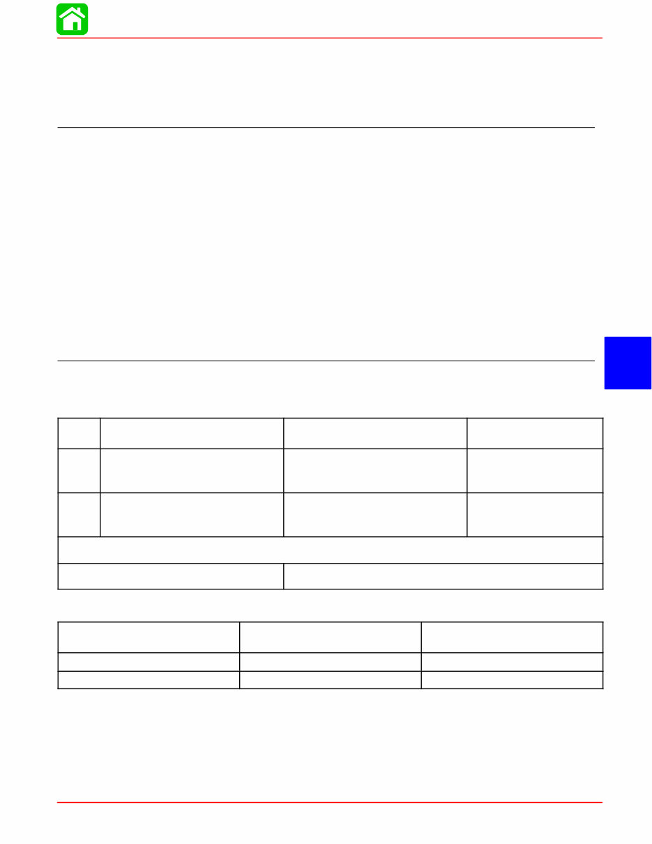
Gear Housing Specifications (Standard Rotation)
Ratio Pinion Depth
Forward Gear
Backlash
Reverse Gear
Backlash
1.87:1
0.025 in. (0.635 mm) With Tool
91-12349A2 using Disc #2 and
Flat #7
0.018 in. to 0.027 in. (0.460 mm
to 0.686 mm) Pointer on line
mark #1
0.030 in. to 0.050 in.
(0.762 mm to 1.27 mm)
2.00:1
0.025 in. (0.635 mm)With Tool
91-12349A2 using Disc #2 and
Flat #7
0.015 in. to 0.022 in. (0.38 mm to
0.56 mm) Pointer on line mark #2
0.030 in. to 0.050 in.
(0.762 mm to 1.27 mm)
Gearcase Lubricant Capacity
All Ratios 22.5 fl. oz. (665.4 ml)
Gear Ratio Teeth on Pinion Gear Teeth on Forward and Reverse
Gear
1.87:1 15 28
2.00:1 12 24
RIGHT HAND NON-RATCHETING
Page 6A-2 90-883728 JULY 2001
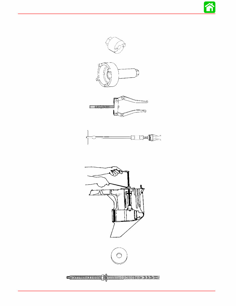
Special Tools
1. Shift Shaft Bushing Tool 91-31107T
2. Gear Housing Cover Nut Tool 91-61069T
3. Bearing Carrier Removal Tool 91-46086A1 and Puller Bolt 91-85716
4. Slide Hammer Puller 91-34569A1
5. Bearing Removal and Installation Kit 91-31229A7. This kit contains the following
tools: Pilot 91-36571T; Puller Rod 91-31229; Nut 11-24156; Puller Plate 91-29310;
Mandrel 91-38628T; and Driver Rod 91-37323.
6. Pilot 91-36571T
7. Puller Rod 91-31229 and Nut 91-24156
RIGHT HAND NON-RATCHETING
90-883728 JULY 2001 Page 6A-3
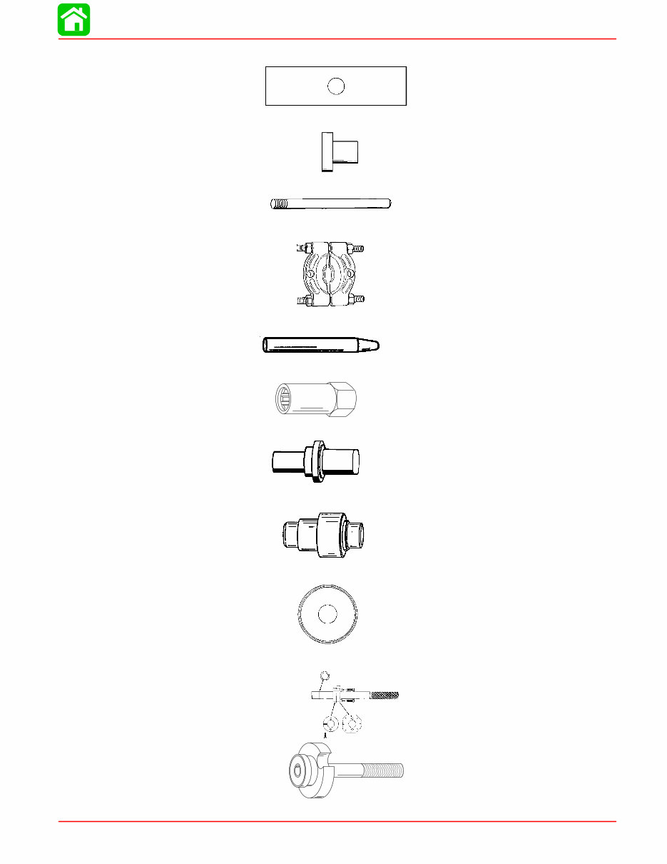
8. Puller Plate 91-29310
9. Mandrel 91-38628T
10. Driver Rod 91-37323
11. Universal Puller Plate 91-37241
12. Cross Pin Tool 91-86642
13. Driveshaft Holding Tool 91-90094
14. Oil Seal Driver 91-31108T
15. Forward Gear Bearing Tool 91-86943T
16. Bearing Driver Cup 91-31106
17. Pinion Locating Gear Tool 91-12349A2 or 91-74776T
RIGHT HAND NON-RATCHETING
Page 6A-4 90-883728 JULY 2001
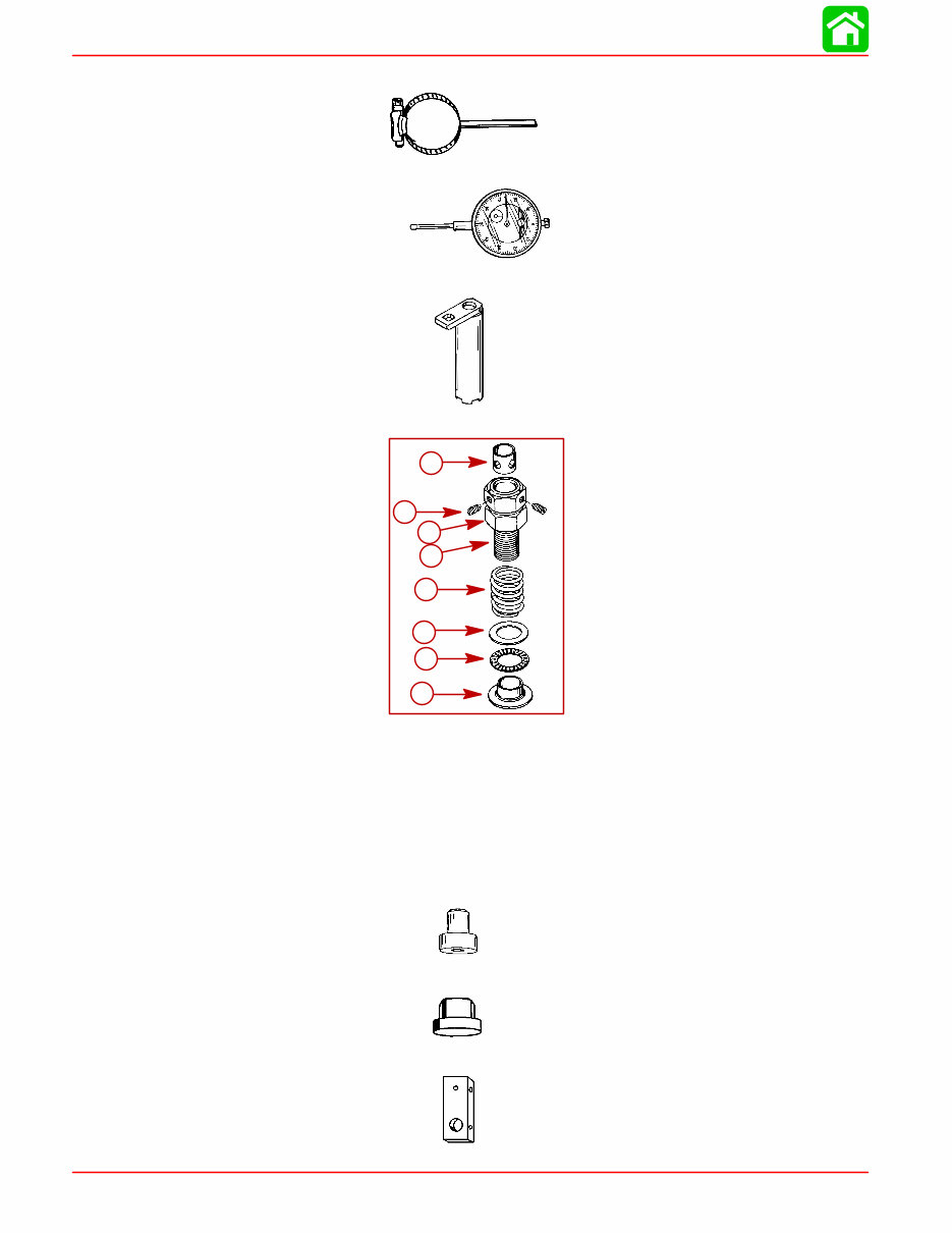
18. Backlash Indicator Rod 91-78473
19. Dial Indicator 91-58222A1
20. Bearing Retainer Tool 91-43506T
21. Bearing Preload Tool 91-14311A2
a
b
c
d
e
f
g
h
1
2
3
4
5
6
7
8
1- Adaptor (N.S.S.)
2- Bearing (N.S.S.)
3- Washer (N.S.S.)
4- Spring (24-14111)
5- Bolt (10-12580)
6- Nut (11-13953)
7- Set Screw (10-12575)
8- Sleeve (23-13946)
22. Mandrel 91-92788
23. Mandrel 91-15755
24. Dial Indicator Holder 91-89897

RIGHT HAND NON-RATCHETING
90-883728 JULY 2001 Page 6A-5
Notes:
RIGHT HAND NON-RATCHETING
Page 6A-6 90-883728 JULY 2001
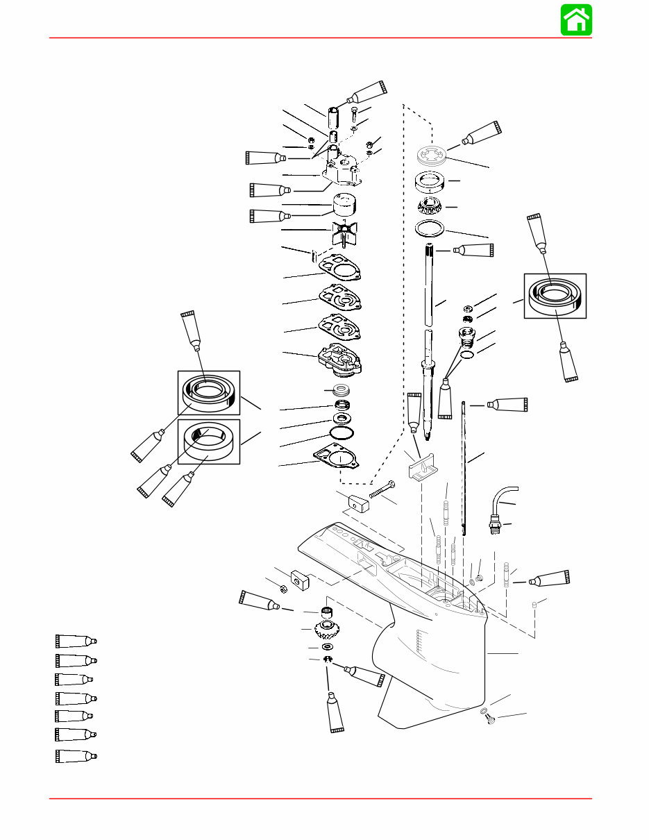
Gear Housing (Drive Shaft)(Standard Rotation)
19
1
12
2
3
4
5
6
7
9
11
14
15
16
17
18
19
20
21
22
23
24
25
26
28
29
31
32
33
34
35
36
37
38
39
40
41
42
43
44
45
46
47
48
10
13
9
44
27
30
Liquid Soap (Purchase Locally)
G.E. Sealer RTV #1473
23
95
95
7
95
95
95
33
7
95
95
7
95
19
95
78
23
78
8
95
4.75
IN/120.65MM
TORPEDO DIA.
18
Perfect Seal 19
7 Loctite 271
Loctite 680 33
95
2-4-C with Teflon
92
Loctite 7649 Primer
92
7
RIGHT HAND NON-RATCHETING
90-883728 JULY 2001 Page 6A-7
Gear Housing (Drive Shaft)(Standard Rotation)
REF
TORQUE
REF .
NO.
QTY. DESCRIPTION lb-in lb-ft Nm
1 1 GEAR HOUSING (BLACK)(BASIC)
2 2 DOWEL PIN
3
1 STUD (3-1/8 IN.) (LONG)
3
1 STUD (3-11/16 IN.) (X-LONG)
4 2 STUD (2-1/16 IN.)
5 1 STUD (3-3/8 IN.)
6 2 STUD (3-1/8 IN.)
7 1 FILLER BLOCK
8 1 ROLLER BEARING
9 2 ANODE
10 1 SCREW (M6 x 40)
11 1 NUT 60 7
12
1 HOSE (10 IN. - LONG)
12
1 HOSE (12 IN. - X-LONG)
13 1 FITTING
14
1 PINION GEAR (1.87:1- 15 TEETH)
14
1 PINION GEAR (2:1 - 14 TEETH))
15 1 WASHER
16 1 NUT 75 101
17 AR SHIM (006 thru 048)
18 2 SCREW–drain 60 7
19 2 WASHER
20 1 SHIFT SHAFT
21 1 O-RING
22 1 BUSHING ASSEMBLY 50 68
23 1 OIL SEAL
24 1 WASHER–rubber
25
1 DRIVE SHAFT (LONG)
25
1 DRIVE SHAFT (X-LONG)
26 1 ROLLER BEARING
27 1 CUP
28 1 RETAINER 100 135
29 1 WATER PUMP BASE
30 1 RETAINER
31 1 GASKET
32 1 O-RING
33 1 OIL SEAL
34 1 OIL SEAL
35 1 GASKET–lower
36 1 GASKET–upper
37 1 FACE PLATE
38 1 WATER PUMP BODY ASSEMBLY
39 1 INSERT
40 1 SEAL–rubber
41 1 lMPELLER
42 1 KEY
43 1 SCREW (#14-8 x 2-1/4 IN.) 35 4
44 2 WASHER
45 2 NUT 50 5.5
46 1 WASHER
47 1 NUT 50 5.5
48 1 SLEEVE
RIGHT HAND NON-RATCHETING
Page 6A-8 90-883728 JULY 2001
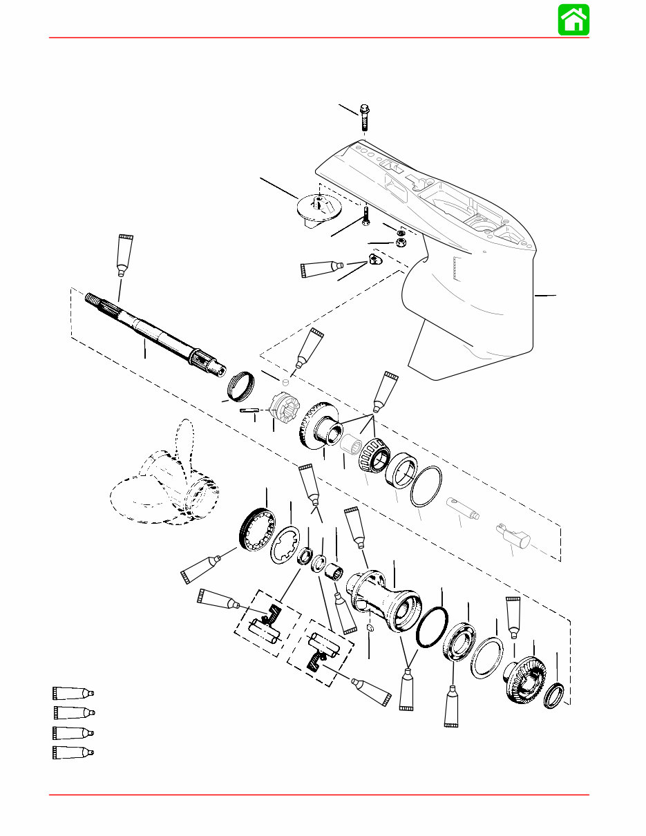
Gear Housing (Prop Shaft)(Standard Rotation)
1
49
50
51
52
53
54
56
57
58
59
60
61
62
63
64
65
66
67
68
69
70
71
72
73
74
75
76
77
78
55
95
95
87
95
95
87
87
95
95
95
87
7
94
4.75
IN/120.65MM
TORPEDO DIA.
7 Loctite 271
94 Anti-Corrosion Grease
95 2-4-C with Teflon
87 Quicksilver Gear Lubricant

RIGHT HAND NON-RATCHETING
90-883728 JULY 2001 Page 6A-9
Gear Housing (Prop Shaft)(Standard Rotation)
REF
TORQUE
REF .
NO.
QTY. DESCRIPTION lb-in lb-ft Nm
1 1 GEAR HOUSING(BASIC)
49 1 CAM FOLLOWER
50 1 SHIFT CAM
51 1 ROD
52
1 FORWARD GEAR (1.87:1 – 15/28)(150)
52
1 FORWARD GEAR (2:1 – 14/28)(115/135)
53 AR SHIM (.006 thru 050)
54 1 TAPERED ROLLER BEARING
55 1 CUP
56 1 NEEDLE BEARING
57 1 CLUTCH
58 1 CROSS PIN
59 1 DETENT PIN
60 1 SPRING
61 1 PROPELLER SHAFT
62
1 REVERSE GEAR (1.87:1 - 15/28)
62
1 REVERSE GEAR (2:1 – 14/28)
63 1 THRUST SPACER
64 1 THRUST RING
65 1 BALL BEARING
66 1 O-RING
67 1 BEARING CARRIER ASSEMBLY
68 1 ROLLER BEARING
69 1 OIL SEAL (INSIDE)
70 1 OIL SEAL (OUTSIDE)
71 1 KEY
72 1 TAB WASHER
73 1 COVER 210 285
74
1 TRIM TAB
74
1 ANODIC PLATE (TRACKER/150 LONG)
75 1 SCREW (1-3/4 IN.) 25 34
76 1 SCREW (3/8-16 x 1 IN.) 30 41
77 2 WASHER
78 2 NUT 50 68

RIGHT HAND NON-RATCHETING
Page 6A-10 90-883728 JULY 2001
General Service Recommendations
There may be more than one way to “disassemble” or “reassemble” a particular part(s),
therefore, it is recommended that the entire procedure be read prior to repair.
IMPORTANT: Read the following before attempting any repairs.
In many cases, disassembly of a sub-assembly may not be necessary until cleaning and
inspection reveals that disassembly is required for replacement of one or more compo-
nents.
Service procedure order in this section is a normal disassembly-reassembly sequence.
It is suggested that the sequence be followed without deviation to assure proper repairs.
When performing partial repairs, follow the instructions to the point where the desired
component can be replaced, then proceed to “reassembly and installation” of that compo-
nent in the reassembly part of this section. Use the “Table of Contents” (on back of section
divider) to find correct page number.
Threaded parts are right hand (RH), unless otherwise indicated.
When holding, pressing or driving is required, use soft metal vise jaw protectors or wood
for protection of parts. Use a suitable mandrel (one that will contact only the bearing race)
when pressing or driving bearings.
Whenever compressed air is used to dry a part, be sure that no water is present in air line.
BEARINGS
Upon disassembly of gear housing, all bearings must be cleaned and inspected. Clean
bearings with solvent and dry with compressed air. Air should be directed at the bearing
so that it passes thru the bearing. DO NOT spin bearing with compressed air, as this may
cause bearing to score from lack of lubrication. After cleaning, lubricate bearings with
Quicksilver Gear Lubricant. DO NOT lubricate tapered bearing cups until after inspection.
Inspect all bearings for roughness, catches and bearing race side wear. Work inner bear-
ing race in-and-out, while holding outer race, to check for side wear.
When inspecting tapered bearings, determine condition of rollers and inner bearing race
by inspecting bearing cup for pitting, scoring, grooves, uneven wear, imbedded particles
and/or discoloration from overheating. Always replace tapered bearing and race as a set.
Roller bearing condition is determined by inspecting the bearing surface of the shaft that
the roller bearing supports. Check shaft surface for pitting, scoring, grooving, imbedded
particles, uneven wear and/or discoloration from overheating. The shaft and bearing must
be replaced, if the conditions described are found.
SHIMS
Keep a record of all shim amounts and location during disassembly to aid in reassembly.
Be sure to follow shimming instructions during reassembly, as gears must be installed to
correct depth and have the correct amount of backlash to avoid noisy operation and pre-
mature gear failure.
SEALS
As a normal procedure, all O-rings and oil seals SHOULD BE REPLACED without regard
to appearance. To prevent leakage around oil seals, apply Loctite 271 to outer diameter
of all metal case oil seals. When using Loctite on seals or threads, surfaces must be clean
and dry. To ease installation, apply Quicksilver 2-4-C w/Teflon Marine Lubricant on all
O-rings. To prevent wear, apply Quicksilver 2-4-C w/Teflon Marine Lubricant on l.D. of oil
seals.
You're Reading a Preview
What's Included?
Fast Download Speeds
Offline Viewing
Access Contents & Bookmarks
Full Search Facility
Print one or all pages of your manual
$31.99
Viewed 33 Times Today


Secure transaction
What's Included?
Fast Download Speeds
Offline Viewing
Access Contents & Bookmarks
Full Search Facility
Print one or all pages of your manual
$31.99
- Get the complete service and repair manual for the 2002-2004 Mercury 150/175/200 HP 2-Stroke EFI Outboards.
- Perfect for both professional mechanics and DIY enthusiasts.
- Includes troubleshooting charts, step-by-step procedures, clear images, and exploded-view illustrations.
- Ensure your outboard's reliability and save on repairs with the manufacturer's recommended procedures.
- Convenient digital format allows easy access, search, and portability on various electronic devices.
- Printable for those who prefer a physical copy.
- Language: English
- Requirements: Adobe Reader (free)
Keep your outboard in top condition with this comprehensive manual.


