

MERCURY MARINER OUTBOARD 99HP 15HP FOUR Stroke Workshop Repair Manual All 1998 Onwards Models Covered
What's Included?
Fast Download Speeds
Offline Viewing
Access Contents & Bookmarks
Full Search Facility
Print one or all pages of your manual

7
B
TILLER HANDLE
90-856159R1 AUGUST 1998 Page 7B-1
ATTACHMENTS/CONTROL LINKAGE
Section 7B – Tiller Handle
Table of Contents
Tiller Handle 7B-2 . . . . . . . . . . . . . . . . . . . . . . . . . . . . . .
Throttle Cable/Linkage Installation and
Adjustment 7B-4 . . . . . . . . . . . . . . . . . . . . . . . . . . . . . . .
Throttle Cables 7B-4 . . . . . . . . . . . . . . . . . . . . . . . . .
Side Shift Models 7B-4 . . . . . . . . . . . . . . . . . . . . . . .
Throttle Cables 7B-6 . . . . . . . . . . . . . . . . . . . . . . . . .
Front Shift Models 7B-6 . . . . . . . . . . . . . . . . . . . . . .
Linkage 7B-8 . . . . . . . . . . . . . . . . . . . . . . . . . . . . . . .
Preparing Tiller Handle Assembly for
Removal 7B-11 . . . . . . . . . . . . . . . . . . . . . . . . . . . . . . . .
Tiller Handle Assembly Removal 7B-11 . . . . . . . . . . .
Tiller Handle Disassembly 7B-11 . . . . . . . . . . . . . . . . .
Cleaning/Inspection/Repair 7B-15 . . . . . . . . . . . . . . . .
Tiller Handle Reassembly 7B-16 . . . . . . . . . . . . . . . . .
Tiller Handle Installation 7B-20 . . . . . . . . . . . . . . . . . . .
Following Tiller Handle Installation 7B-20 . . . . . . . . . .
TILLER HANDLE
Page 7B-2 90-856159R1 AUGUST 1998
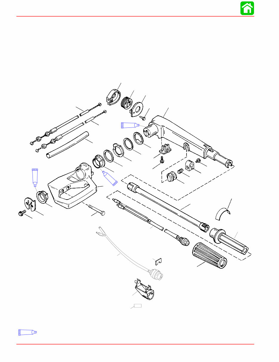
Tiller Handle
1
2
3
4
5 7
8
9
10
11
12
13
14
15
16
17
18
19
20
21
22
23
24
25 26
27
28 29
5
6
20
21
30
95
2-4-C w/Teflon (92-850736A1)
95
95
95

TILLER HANDLE
90-856159R1 AUGUST 1998 Page 7B-3
Tiller Handle
REF
TORQUE
REF .
NO.
QTY. DESCRIPTION lb-in. lb-ft Nm
– 1 TILLER HANDLE ASSEMBLY (BLACK)
– 1 TILLER HANDLE ASSEMBLY (GRAY)
1 1 COVER
2 1 PULLEY
3 1 CASE
4 1 SCREW (10-16 x 1/2) Drive Tight
5 2 THROTTLE CABLE
6 1 SLEEVE
7 1 STEERING HANDLE ARM
8 2 BOLT (M5 x 16) 70 8
9 1 BOLT (M5 x 16) 50 5.6
10 1 KNOB-Throttle Friction
11 1 SPRING
12 1 LOCK-Throttle Friction
13 1 BOLT (M6 x 25) Hand Tight
14 1 TILLER TUBE
15 1 DECAL
16 1 THROTTLE HANDLE
17 1 GRIP
18 1 STOP SWITCH
19 1 RETAINER
20 2 BUSHING
21 2 WASHER
22 1 WAVE WASHER
23 1 WASHER
24 1 BRACKET-Steering Arm
25 2 BOLT (M10 X 80) 32.5 44
26 1 PLATE
27 1 SWITCH HOUSING
28 1
CLIP ELECTRIC HANDLE
29 1 SWITCH
30 1 DECAL-Start
TILLER HANDLE
Page 7B-4 90-856159R1 AUGUST 1998
Throttle Cable/Linkage Installation and Adjustment
Throttle Cables
SIDE SHIFT MODELS
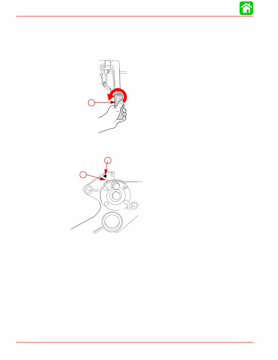
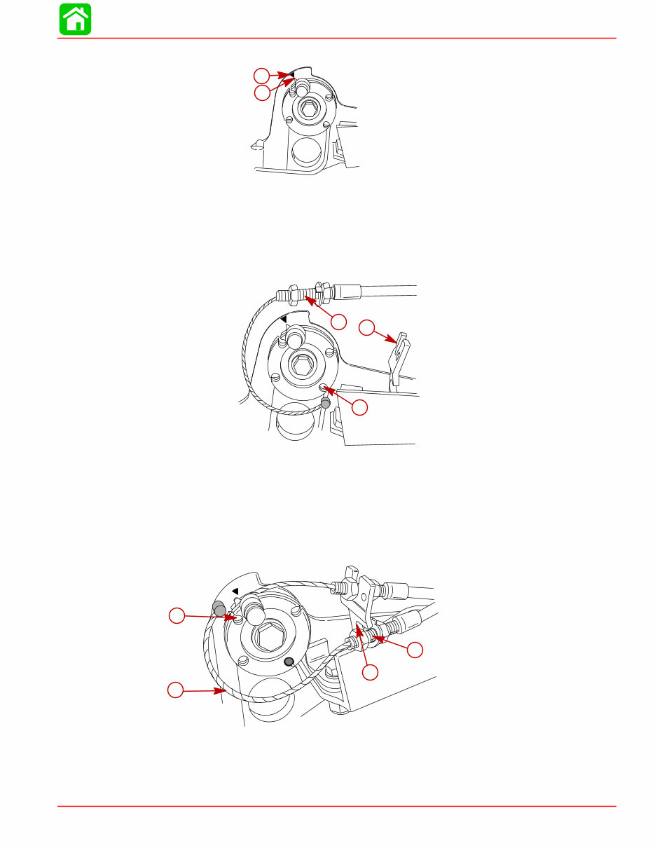
1. Rotate the tiller twist grip to full counterclockwise position.
a
a- Wide Open Throttle Position
2. Rotate pulley to align the pointer with the match mark on the bracket as shown below.
b
a
a- Pulley Pointer
b- Match Mark
TILLER HANDLE
90-856159R1 AUGUST 1998 Page 7B-5
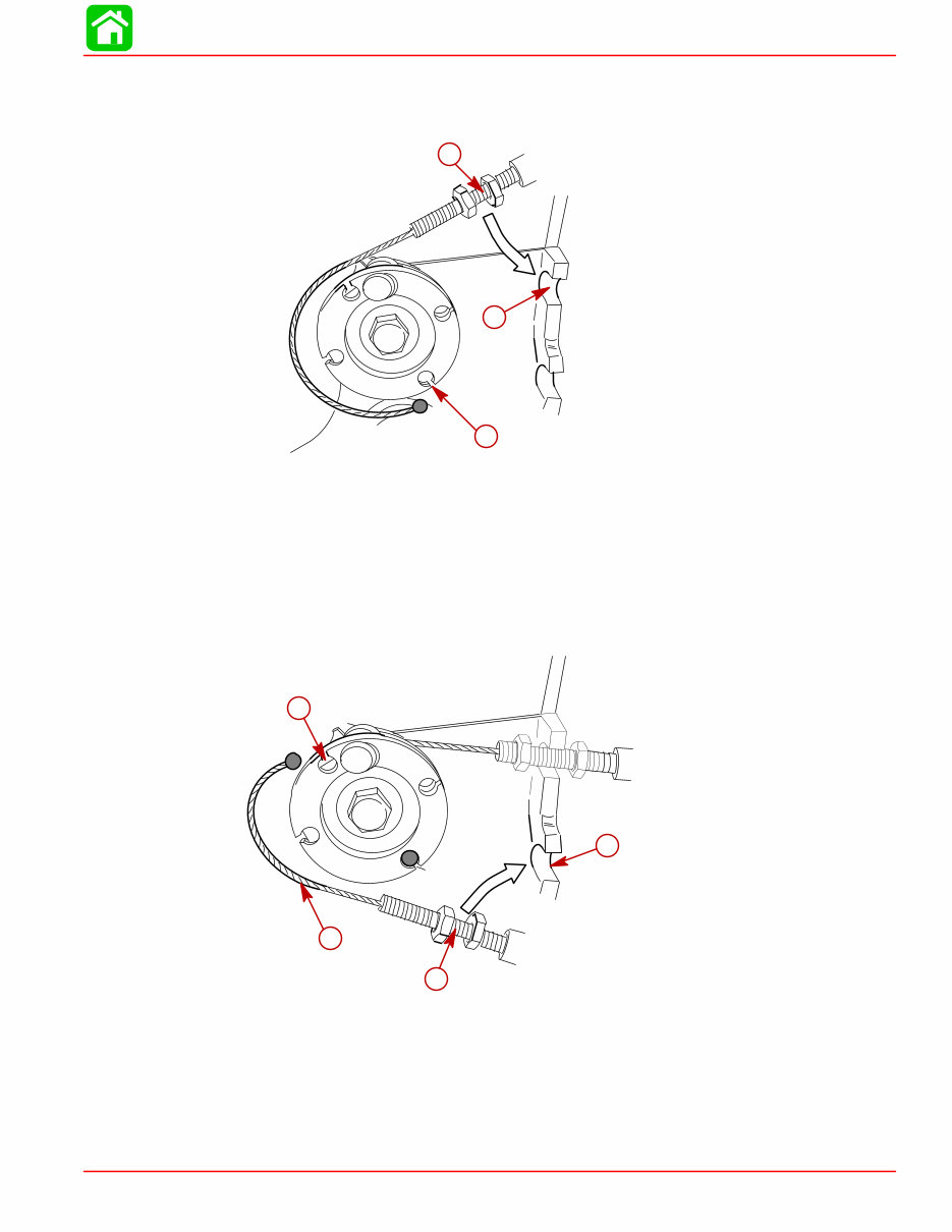
3. Install longest cable barrel into anchor “a”.
4. Wrap longest cable into inner groove around top side of pulley. Place cable jacket into
upper anchor bracket.
a
c
b
a- Anchor “a”
b- Cable Jacket
c- Upper Anchor Bracket
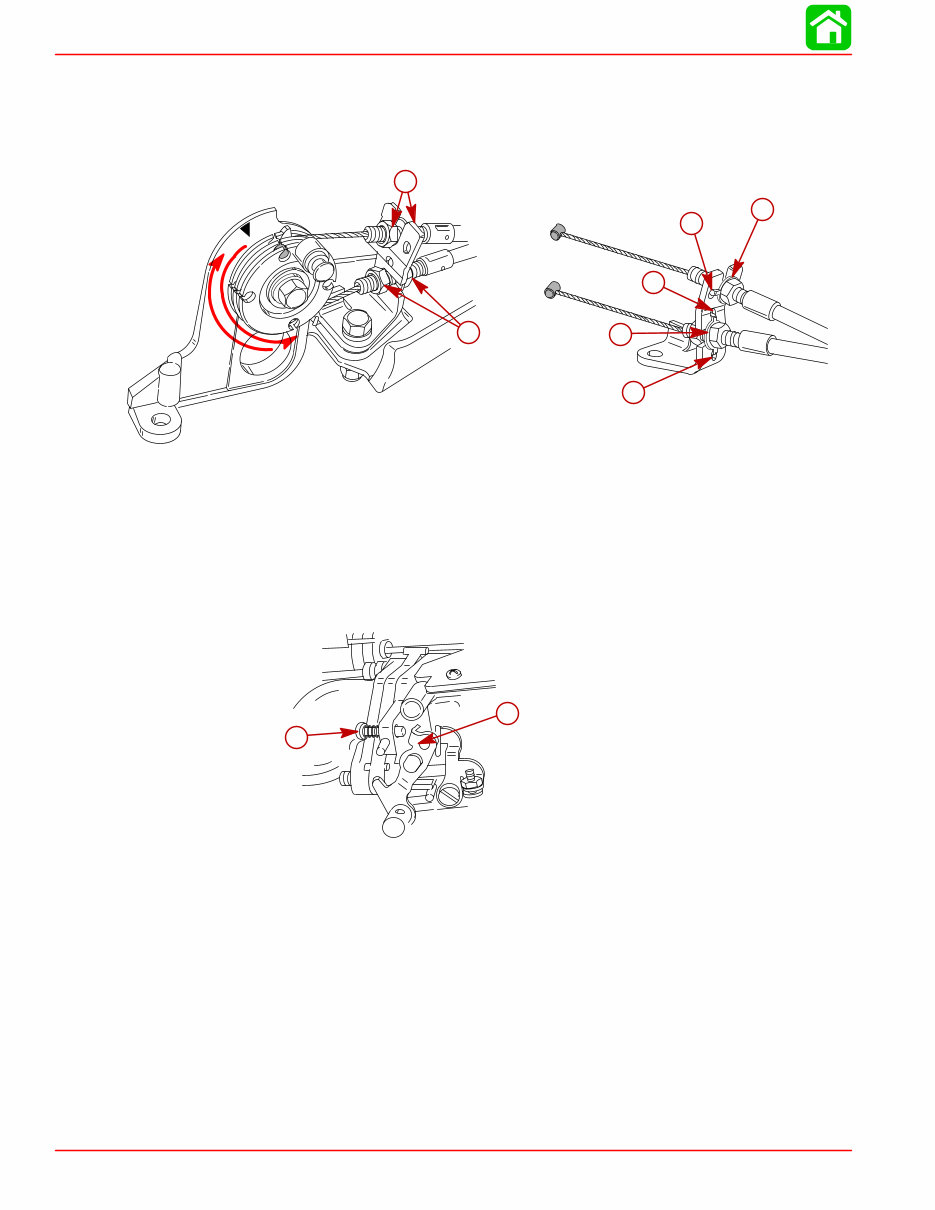
5. Rotate tiller twist grip to full clockwise (idle) position.
6. Install remaining barrel into anchor “b”.
7. Place remaining cable into outer groove, wrap around to bottom side of pulley. Place
cable jacket into lower anchor bracket.
a
b
c
d
a- Remaining Cable
b- Anchor “b”
c- Cable Jacket
d- Lower Anchor Bracket
TILLER HANDLE
Page 7B-6 90-856159R1 AUGUST 1998
8. Position locking tab washer into respective tab slot and hole.
a
c
b
a
a- Locking Tabs
b- Tab Slot
c- Tab Hole
9. Rotate throttle twist grip back to full counterclockwise (wide open throttle) position.
10. Adjust cable lengths using jam nuts to bring match marks into alignment, make adjust-
ments to lower cable first.
11. Remove slack in upper cable by adjusting upper jam nuts. DO NOT OVERTIGHTEN.
a
b
a- Upper Jam Nuts
b- Lower Jam Nuts
12. Rotate tiller throttle handle from idle to wide open throttle to idle again. Verify match
marks are in alignment [± 1/8″(3.175mm)]. Readjust jam nuts if marks are not aligned.
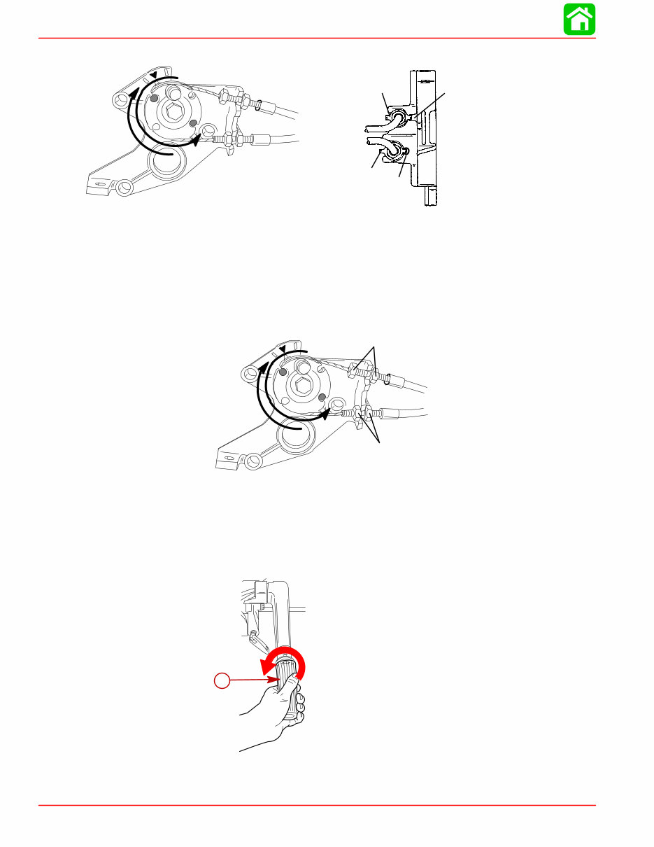
FRONT SHIFT MODELS
1. Rotate the tiller twist grip to full counterclockwise position.
a
a- Wide Open Throttle Position
TILLER HANDLE
90-856159R1 AUGUST 1998 Page 7B-7
2. Rotate pulley to align the pointer with the match mark on the bracket as shown below.
56971
a
b
a- Pulley Pointer
b- Match Mark
3. Install longest cable/barrel into anchor “a”.
4. Wrap longest cable into inner groove around top side of pulley. Place cable jacket into
upper anchor bracket.
56972
a
b
c
a- Anchor “a”
b- Cable Jacket
c- Upper Anchor Bracket
5. Install remaining barrel into anchor “b”.
6. Place remaining cable into outer groove, wrap around to bottom side of pulley. Place
cable jacket into lower anchor bracket.
56973
a
b
c
d
a- Remaining Cable
b- Anchor “b”
c- Cable Jacket
d- Lower Anchor Bracket
TILLER HANDLE
Page 7B-8 90-856159R1 AUGUST 1998
7. Position locking tab washers into respective tab slot and hole.
8. Adjust cable lengths using jam nuts to bring match marks into alignment, make adjust-
ments to lower cable first.
9. Remove slack in upper cable by adjusting upper jam nuts. DO NOT OVERTIGHTEN.
57013
56974
a
a
b
b
b
c
d
a- Locking Tab Washers
b- Tab Hole
c- Upper Jam Nuts
d- Lower Jam Nuts
Linkage
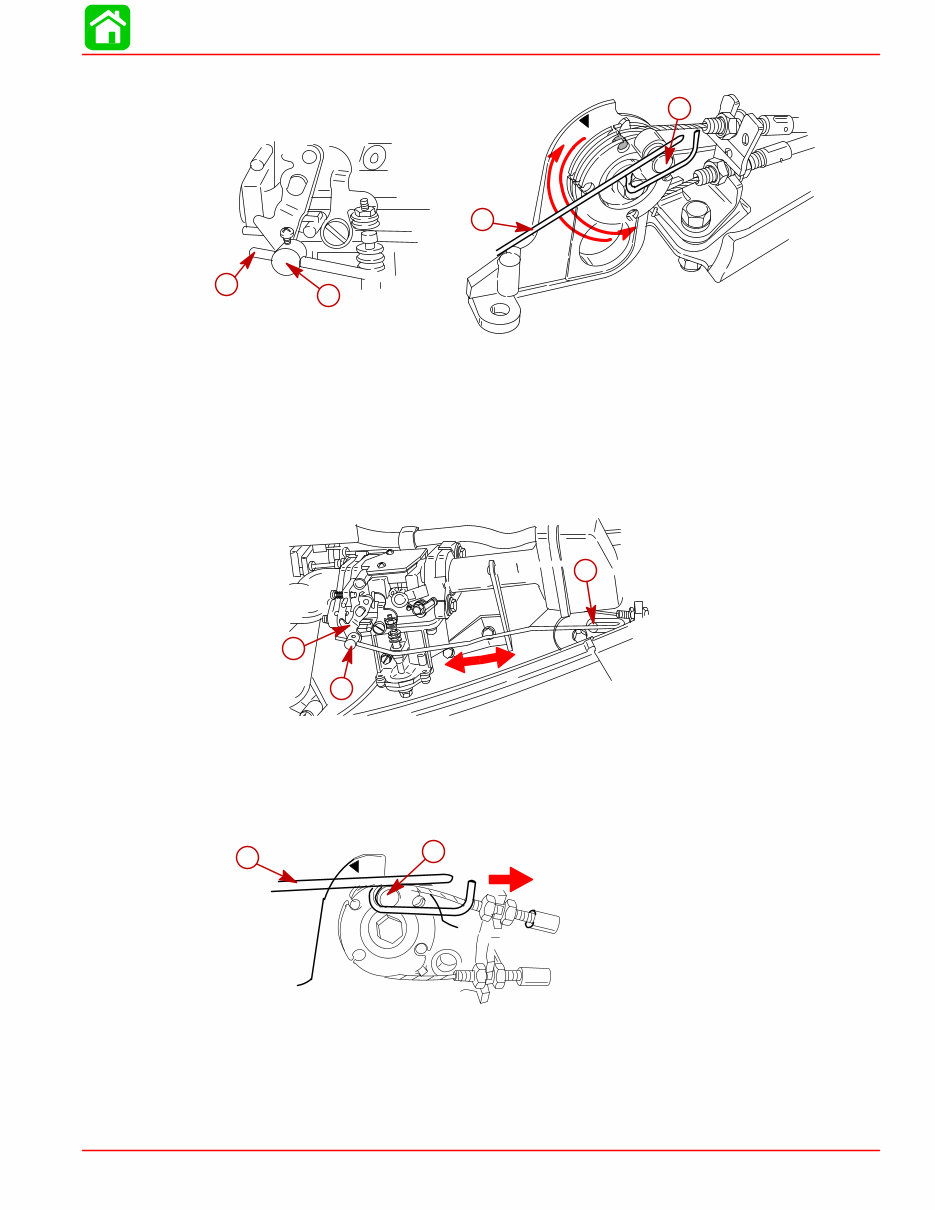
1. Turn idle speed screw counterclockwise until screw is not touching throttle shaft arm.
a
b
a- Idle Speed Screw
b- Throttle Shaft Arm
TILLER HANDLE
90-856159R1 AUGUST 1998 Page 7B-9
2. Install throttle linkage on pulley and throttle barrel.
a
b
56974
c
a
a- Throttle Linkage
b- Throttle Barrel
c- Pulley
3. Check to make sure throttle linkage has free movement between throttle barrel and
pulley.
NOTE: The throttle arm should remain stationary while checking for free movement of
throttle linkage.
a
b
c
a- Throttle Barrel
b- Pulley
c- Throttle Arm
4. Move throttle linkage forward until linkage comes to rest on the pulley boss.
a
b
a- Throttle Linkage
b- Pulley Boss
TILLER HANDLE
Page 7B-10 90-856159R1 AUGUST 1998
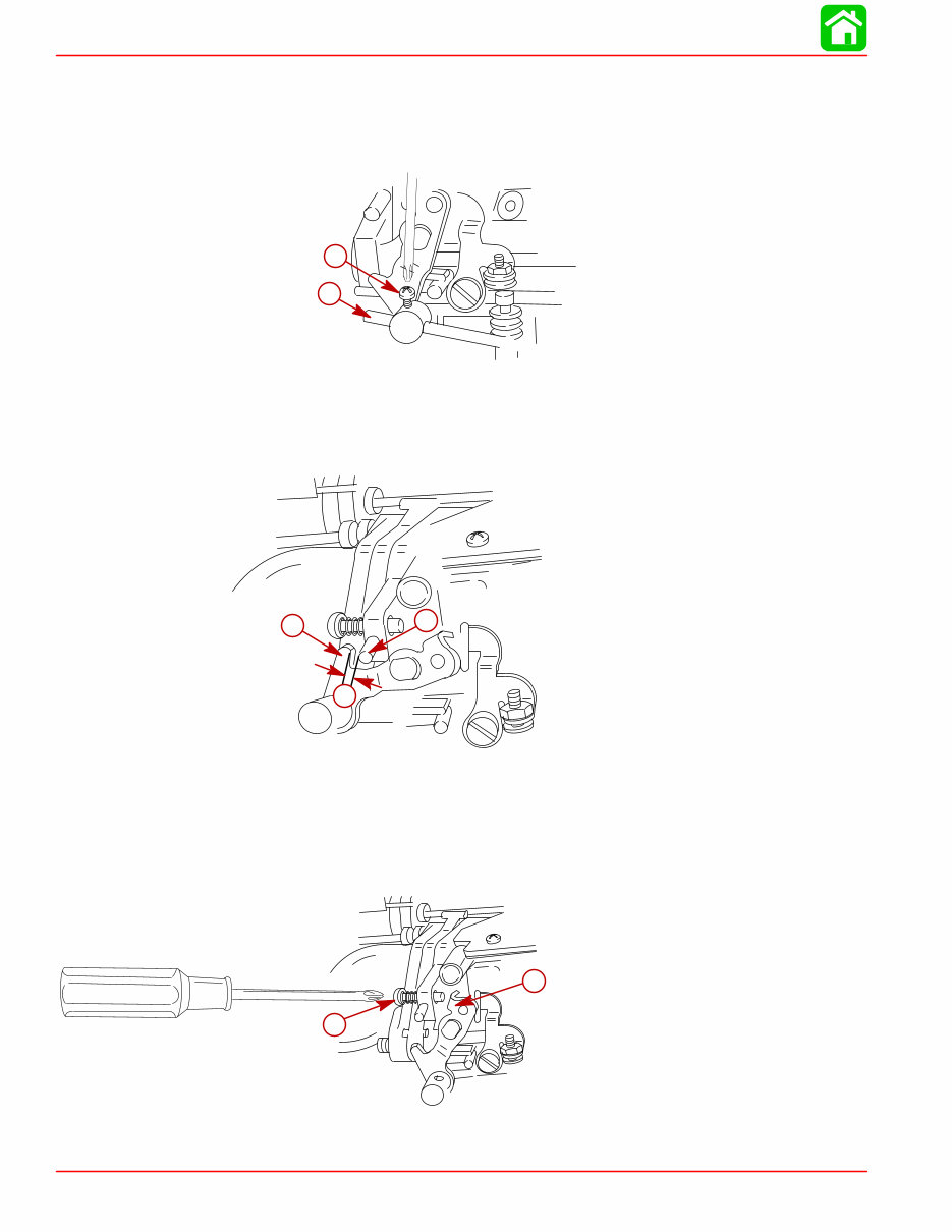
5. Tighten screw on throttle barrel to secure linkage.
NOTE: Over-tightening screw may damage throttle linkage.
NOTE: Check linkage for free movement on pulley. Verify throttle shaft arm in not sticking
and returns to idle position.
a
b
a- Screw
b- Linkage
6. Verify throttle arm does not hit the full throttle stop at wide open throttle. Gap between
stop and throttle arm should be no more than 0.1 in. (2.54 mm).
a
b
c
a- Throttle Stop
b- Throttle Arm
c- Approximately 0.1 in. (2.54 mm) Gap
7. Turn idle speed screw in (clockwise) until it touches the throttle shaft arm, then turn an
additional 1/2 turn for initial setting.
a
b
a- Idle Speed Screw
b- Throttle Shaft Arm
You're Reading a Preview
What's Included?
Fast Download Speeds
Offline Viewing
Access Contents & Bookmarks
Full Search Facility
Print one or all pages of your manual
$27.99
Viewed 56 Times Today


Secure transaction
What's Included?
Fast Download Speeds
Offline Viewing
Access Contents & Bookmarks
Full Search Facility
Print one or all pages of your manual
$27.99
This Workshop Service Repair Manual provides comprehensive technical information necessary for performing all repairs on MERCURY MARINER OUTBOARD 99HP 15HP FOUR STROKE models from 1998 onwards. It includes detailed repair procedures, easy-to-read exploded views, diagrams for identification, disassembly/re-assembly, accurate adjustment, and correct repairs.
The manual also features illustrations, diagrams, specifications, step-by-step instructions, and procedures, making it useful for both professional mechanics and DIY enthusiasts for servicing, teardowns, repairs, overhauls, adjustments, and complete specifications.
It is supplied in instant PDF format and is compatible with all computers, including PC and Mac systems.


