

Mercury Mariner 135/150/175/200 Outboard OEM Service & Repair Manual
What's Included?
Fast Download Speeds
Online & Offline Access
Access PDF Contents & Bookmarks
Full Search Facility
Print one or all pages of your manual
MODELS
United States 0G960500 and Above . . . . . .
With Serial Numbers
SERVICE
MANUAL
135 • 150 • 175 • 200
Printed in U.S.A.
2000, Mercury Marine
90-878079 JANUARY 2000
90-878079 JANUARY 2000 Page i
Notice
Throughout this publication, “Dangers”, “Warnings” and “Cautions” (accompanied by the In-
ternational HAZARD Symbol ) are used to alert the mechanic to special instructions con-
cerning a particular service or operation that may be hazardous if performed incorrectly or
carelessly. OBSERVE THEM CAREFULLY!
These “Safety Alerts” alone cannot eliminate the hazards that they signal. Strict compliance
to these special instructions when performing the service, plus “Common Sense” operation,
are major accident prevention measures.
DANGER
DANGER - Immediate hazards which WILL result in severe personal injury or death.
WARNING
WARNING - Hazards or unsafe practices which COULD result in severe personal in-
jury or death.
CAUTION
Hazards or unsafe practices which could result in minor personal injury or product
or property damage.
Notice to Users of This Manual
This service manual has been written and published by the Service Department of Mercury
Marine to aid our dealers’ mechanics and company service personnel when servicing the
products described herein.
It is assumed that these personnel are familiar with the servicing procedures of these prod-
ucts, or like or similar products manufactured and marketed by Mercury Marine, that they
have been trained in the recommended servicing procedures of these products which in-
cludes the use of mechanics’ common hand tools and the special Mercury Marine or recom-
mended tools from other suppliers.
We could not possibly know of and advise the service trade of all conceivable procedures
by which a service might be performed and of the possible hazards and/or results of each
method. We have not undertaken any such wide evaluation. Therefore, anyone who uses
a service procedure and/or tool, which is not recommended by the manufacturer, first must
completely satisfy himself that neither his nor the products safety will be endangered by the
service procedure selected.
All information, illustrations and specifications contained in this manual are based on the
latest product information available at the time of publication. As required, revisions to this
manual will be sent to all dealers contracted by us to sell and/or service these products.
It should be kept in mind, while working on the product, that the electrical system and ignition
system are capable of violent and damaging short circuits or severe electrical shocks. When
performing any work where electrical terminals could possibly be grounded or touched by
the mechanic, the battery cables should be disconnected at the battery.
Any time the intake or exhaust openings are exposed during service they should be covered
to protect against accidental entrance of foreign material which could enter the cylinders and
cause extensive internal damage when the engine is started.
Page ii 90-878079 JANUARY 2000
It is important to note, during any maintenance procedure replacement fasteners must have
the same measurements and strength as those removed. Numbers on the heads of the met-
ric bolts and on the surfaces of metric nuts indicate their strength. American bolts use radial
lines for this purpose, while most American nuts do not have strength markings. Mis-
matched or incorrect fasteners can result in damage or malfunction, or possibly personal
injury. Therefore, fasteners removed should be saved for reuse in the same locations when-
ever possible. Where the fasteners are not satisfactory for re-use, care should be taken to
select a replacement that matches the original.
Cleanliness and Care of Outboard Motor
A marine power product is a combination of many machined, honed, polished and lapped
surfaces with tolerances that are measured in the ten thousands of an inch/mm. When any
product component is serviced, care and cleanliness are important. Throughout this manu-
al, it should be understood that proper cleaning, and protection of machined surfaces and
friction areas is a part of the repair procedure. This is considered standard shop practice
even if not specifically stated.
Whenever components are removed for service, they should be retained in order. At the
time of installation, they should be installed in the same locations and with the same mating
surfaces as when removed.
Personnel should not work on or under an outboard which is suspended. Outboards should
be attached to work stands, or lowered to ground as soon as possible.
We reserve the right to make changes to this manual without prior notification.
Refer to dealer service bulletins for other pertinent information concerning the products de-
scribed in this manual.
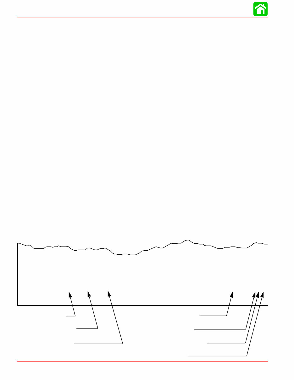
Page Numbering
Two number groups appear at the bottom of each page. The example below is self-explana-
tory.
EXAMPLE:
90-878079R1 OCTOBER 1999
LOWER UNIT - 6A-7
Revision No. 1
Month of Printing
Year of Printing
Section Description
Section Number
Part of Section Letter
Page Number
1
2
3
4
5
6
7
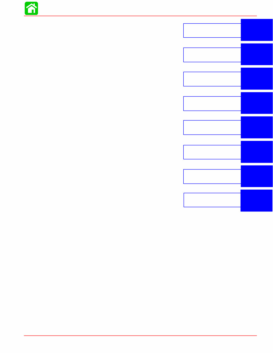
General Information
& Specifications
Ignition System
Fuel System
Powerhead
Mid-Section
Gear Housing
Attachment/Control Linkage
8
Color Diagrams
90-878079 JANUARY 2000 Page iii
Service Manual Outline
Section 1 - General Information & Specifications
A - Specifications
B - Maintenance
C - General Information
D - Outboard Installation
Section 2 - Electrical
A - Ignition
B - Charging & Starting System
C - Timing, Synchronizing & Adjusting
D - Wiring Diagrams
Section 3 - Fuel System
A - Fuel Pump
B - Carburetion
C - Fuel Injection
D - Oil Injection
E - Emissions
Section 4 - Powerhead
A - Powerhead
B - Cooling
Section 5 - Mid-Section
A - Clamp/Swivel Brackets & Drive Shaft Housing
B - Power Trim
Section 6 - Gear Housing
A - Right Hand Non-Ratcheting
B - Left Hand Non-Ratcheting
Section 7 - Attachments/Control Linkage
Section 8 - Color Diagrams

1
A
SPECIFICATIONS
90-878079 JANUARY 2000 Page 1A-1
IMPORTANT INFORMATION
Section 1A - Specifications
Table of Contents
Specifications 1A-1 . . . . . . . . . . . . . . . . . . . . . . . . . . .
Specifications
Model 135/XR6/MAGIII/200/150XRI/175XRI/200XRI
HORSEPOWER
(KW)
Model 135
Model 150XRI
Model XR6/MAGIII
Model 175XRI
Model 200/200XRI
135 (100.6)
150 (111.8)
150 (111.8)
175 (130.5)
200 (149.1)
OUTBOARD
WEIGHT
Model 135
Model XR6/MAGIII/200
Model 150XRI/175XRI/200XRI
413.0 lbs. (188.0 kg)
406.0 lb (184.0 kg)
416.0 lb (189.0 kg)
CYLINDER
BLOCK
Model 135
Type
Displacement
Thermostat
Model XR6/MAGIII/200
150XRI/175XRI/200XRI
Type
Displacement
Thermostat
V–6 Cylinder, Two Cycle, Loop
Charged
121.9 cu. in. (1998cc)
143°F (61.7°C)
V–6 Cylinder, Two Cycle, Loop
Charged
153.0 cu. in. (2507cc)
143°F (61.7°C)
STROKE Length (All Models) 2.650 in. (67.31 mm)
CYLINDER
BORE
Diameter (Std)
– Models 135
– Models XR6/MAGIII/200
150XRI/175XRI/200XRI
Taper/Out of Round/Maximum Wear
Bore Type
3.125 in. (79.375 mm)
3.501 in. (88.925 mm)
0.003 in. (0.076 mm)
Cast Iron
CRANKSHAFT Maximum Runout 0.006 (0.152 mm)

SPECIFICATIONS
Page 1A-2 90-878079 JANUARY 2000
PISTON Piston Type
Models 135
Standard
0.015 in. (0.381 mm) Oversize
0.030 in. (0.762 mm) Oversize
Models XR6/MAGIII/200
150XRI/175XRI/200XRI
Standard
0.015 in. (0.381 mm) Oversize
Aluminum
3.115 in. ± 0.002 in.
(79.121 mm ± 0.051 mm)
3.130 in. ± 0.002 in.
(79.502 mm ± 0.051 mm)
3.145 in. ± 0.002 in.
(79.883 mm ± 0.051 mm)
3.494 in. ± 0.001 in.
(88.748 mm ± 0.025 mm)
3.509 in. ± 0.001 in.
(89.129 mm ± 0.025 mm)
COMPRESSION All Models – Using a fully charged bat-
tery, throttle shutters wide open and
cylinder block warm
110 – 135 psi
(753.3 – 924.5 kPa)
Variance between cylinders should not
exceed 15 psi (102.7 kPa)
REEDS Model 135
Model XR6/MAGIII/200
Model 150XRI/175XRI/200XRI
Reed Type
Reed Stand 0pen (Max.)
Reed Stop (Max.)
Steel
0.020 in. (0.50 mm)
Not Adjustable
MID
SECTION
Power Trim (Total Tilt Range)
Power Trim (Tilt Range)
Maximum Allowable Leak down in 24
hrs.
Tilt Pin Adjustment Positions
Steering Pivot Range
Allowable Transom Thickness
75°
20°
1 in. (25.4 mm)
5
60°
2-3/8 in. (6.03 cm) Maximum
FUEL
SYSTEM
Fuel
Recommended Gasoline
Model 135
Model XR6/MAGIII/200
Model 150XRI/175XRI/200XRI
Recommended Oil
Model 135
Model XR6/MAGIII/200
Model 150XRI/175XRI/200XRI
Gasoline/Oil Ratio
Fuel Pressure Pulse Driven Pump
– @ Idle
– @ WOT
Gasoline w/Oil Injection
Unleaded 87 Octane Minimum
Quicksilver TC-W3 2 Cycle Outboard
Oil Only
50:1 (25:1 Break-In)
1 – 3 psi (6.8 – 20.5 kPa)
12 psi (82.1 kPa) Minimum
STARTING
SYSTEM
Manual Start – All Models
Electric Start – All Models
Starter Draw (Under Load)
Starter Load (No Load)
Battery Rating
Emergency Start Rope
175 Amperes
40 Amperes
Min. 630 Marine Cranking Amps
(MCA) or 490 Cold Cranking Amps
(CCA)

SPECIFICATIONS
90-878079 JANUARY 2000 Page 1A-3
IGNITION
SYSTEM
Type
Spark Plug Type
Spark Plug Gap
Firing Order
Capacitor Discharge
NGK BPZ8HS-10
0.040 in. (1.0 mm)
1-2-3-4-5-6
CHARGING
SYSTEM
Alternator Output (Regulated)
Voltage Regulator Draw with Ignition
Key in the Off Position
40 Amperes @ 5000 rpm
0 – 4 Milliamperes Each
(0 – 8 Milliamperes total system draw)
TIMING Idle Speed/Pickup Timing
– 135 Carb Models
– XR6/MAG III
– 200 Carb
– 150XRI/175 XRI Models
– 200 XRI Model
Maximum BTDC
– Model 135
@ Cranking Speed
@ WOT RPM
– XR6/MAG III Carb/175 XRI
@ Cranking Speed
@ WOT RPM
– Model 150 XRI
@ Cranking Speed
@ WOT RPM
– Model 200 Carb
@ Cranking Speed
@ WOT RPM
– Model 200XRI
@ Cranking Speed
@ WOT RPM
0° – 9° ATDC
25° BTDC
19° BTDC
26° BTDC
20° BTDC
22° BTDC
16° BTDC
20° BTDC
18° BTDC
24° BTDC
18° BTDC
*NOTE: Timing specifications listed are for 2000 model year engines. Refer to timing decal on engine for
previous model year timing specifications.

SPECIFICATIONS
Page 1A-4 90-878079 JANUARY 2000
GEAR
HOUSING
Gear Ratio
– Models 135
– Models XR6/MAGIII/150XRI
– Models 200/175XRI/200XRI
Gear Ratio – High Altitude
– Models 135
– Models XR6/MAGIII/175/200
150XRI/175XRI/200XRI
Gearcase Capacity
– 1.87:1/2.00:1/2.30:1
Pinion Height
– All Models
Forward Gear Backlash
– 1.87:1 Ratio
– 2.00:1 Ratio
– 2.30:1 Ratio
Water Pressure @ rpm
2.00:1 (14/28 teeth)
1.87:1 (15/28 teeth)
1.87:1 (15/28 teeth)
2.30:1 (13/30 teeth)
2.00:1 (14/28 teeth)
22.5 fl oz (665.4 ml)
0.025 in. (0.64 mm)
0.018 in. – 0.027 in.
(0.460 mm – 0.686 mm)
0.015 in. – 0.022 in.
(0.381 mm – 0.558 mm)
0.018 in. – 0.023 in.
(0.460 mm – 0.584 mm)
12 psi Minimum @ 5500 rpm
OIL
INJECTION
Recommended Oil
Oil Tank Capacity
Approx. Time
– Model 135
– Model XR6/MAGIII/175/200
– Model 150XRI/175XRI/200XRI
Reserve Capacity/Approx. Time
Output @ 1000 RPM for 3 Minutes
with Pump @ Full Open
– Model 135
– Model XR6/MAG III/200
– Model 150XRI/175XRI/200XRI
Quicksilver TC-W3
3 gal. (11.4 Liter)
8.7 hrs. Approx.
6.6 hrs. Approx.
6.6 hrs. Approx.
.94 qt. (0.89 Liter) 30 – 35 min.
12cc @ 1000 rpm
15cc @ 1000 rpm
15cc @ 1000 rpm
FUEL
INJECTION
Idle RPM
– All Models
Wide Open Throttle (WOT) RPM
– Model 150XRI/175XRI
– Model 200XRI
Float Adjustment (Vapor Separator)
Float Level
Injectors
– All Models (Quantity)
– CDM # Controls:
– #1 Primary Circuit
– #3 Primary Circuit
– #5 Primary Circuit
Line Pressure @ Injectors
650 ± 50
5000 – 5600
5000 – 5800
Preset @ Factory
6
#3 and #4 Injectors
#5 and #6 Injectors
#1 and #2 Injectors
34 psi – 36 psi (234 kPa – 248 kPa)

SPECIFICATIONS
90-878079 JANUARY 2000 Page 1A-5
CARBURETOR Idle RPM
– Model 135/200
– Model XR6/MAGIII
Wide Open Throttle (WOT) RPM
– Model 135/200
– Model XR6/MAGIII
Idle Mixture Screw Adjustment
(Preset - Turns Out)
– Carburetor Model 135
– Carburetor Models 150/200
– All EFI Models
Float Adjustment
Float Level
650 ± 50
675 ± 50
5000 – 5500
5000 – 5500
1-1/2 ± 1/8
1-1/4 ± 1/8
Not Adjustable
Float Even with Bowl Edge w/Bowl
Inverted
CARBURETOR WMV Carburetor Jets
– Model 135 (WMV 15)
– Main Jet
– Idle Air Jet
– Vent Jet
– Model XR6/MAGIII (WMV 16)
– Main Jet
– Idle Air Jet
– Vent Jet
– Model 200 (WMV 18)
– Main Jet
– Idle Air Jet
– Vent Jet
.072 (all cylinders)
Cyl. 2,4 – .040
Cyl. 1 – .036
Cyl. 3 - .030
Cyl. 6 - .048
Cyl. 5 - .038
.086 (all cylinders)
.074 (all cylinders)
Cyl. 1,2,3,4,5 – .044
Cyl. 6 – .048
.082 (all cylinders)
Cyl 2,3 – .082
Cyl. 1,4 – .080
Cyl. 5 – .084
Cyl. 6 – .078
Cyl. 2 – .038
Cyl. 1 – .042
Cyl. 3,4,5,6 – .028
.086 (all cylinders)

1
B
MAINTENANCE
90-878079 JANUARY 2000 Page 1B-1
IMPORTANT INFORMATION
Section 1B - Maintenance
Table of Contents
Specifications 1B-1 . . . . . . . . . . . . . . . . . . . . . . . . . . . . . . . .
Gear Case Lubricant Capacity 1B-1 . . . . . . . . . . . . . .
Special Tools 1B-2 . . . . . . . . . . . . . . . . . . . . . . . . . . . . . . . .
Quicksilver Lubricant/Sealant 1B-2 . . . . . . . . . . . . . . . . . .
Inspection and Maintenance Schedule 1B-4 . . . . . . . . . .
Before Each Use 1B-4 . . . . . . . . . . . . . . . . . . . . . . . . . .
After Each Use 1B-4 . . . . . . . . . . . . . . . . . . . . . . . . . . . .
Every 100 Hours of Use or Once Yearly,
Whichever Occurs First 1B-4 . . . . . . . . . . . . . . . . . . . .
Flushing Engine 1B-5 . . . . . . . . . . . . . . . . . . . . . . . . . . . . . .
Flushing Cooling System –
Using Cowl Flush Plug 1B-5 . . . . . . . . . . . . . . . . . . . . .
Flushing Cooling System – Using Flushing
Attachment 44357A2 1B-5 . . . . . . . . . . . . . . . . . . . . . .
Fuel System 1B-6 . . . . . . . . . . . . . . . . . . . . . . . . . . . . . . . . .
Fuel Line Inspection 1B-6 . . . . . . . . . . . . . . . . . . . . . . .
Fuel Line Filter (Models With Carburetors) 1B-6 . . . .
Water Separating Fuel Filter – EFI Models 1B-7 . . . .
Corrosion Control Anode 1B-7 . . . . . . . . . . . . . . . . . . . . . .
Spark Plug Inspection 1B-8 . . . . . . . . . . . . . . . . . . . . . . . . .
Battery Inspection 1B-8 . . . . . . . . . . . . . . . . . . . . . . . . . . . .
Fuse Replacement 1B-9 . . . . . . . . . . . . . . . . . . . . . . . . . . .
Lubrication Points 1B-9 . . . . . . . . . . . . . . . . . . . . . . . . . . . .
Checking Power Trim Fluid 1B-11 . . . . . . . . . . . . . . . . . . .
Gear Case Lubrication 1B-12 . . . . . . . . . . . . . . . . . . . . . . .
Storage Preparation 1B-13 . . . . . . . . . . . . . . . . . . . . . . . . .
Specifications
Gear Case Lubricant Capacity
Gear Case Ratio Capacity
1.87:1 22.5 fl. oz. (717 ml)
2.00:1 22.5 fl. oz. (717 ml)
2.30:1 22.5 fl. oz. (717 ml)
You're Reading a Preview
What's Included?
Fast Download Speeds
Online & Offline Access
Access PDF Contents & Bookmarks
Full Search Facility
Print one or all pages of your manual
$31.99
Viewed 51 Times Today


Secure transaction
What's Included?
Fast Download Speeds
Online & Offline Access
Access PDF Contents & Bookmarks
Full Search Facility
Print one or all pages of your manual
$31.99
This is a comprehensive OEM service and repair manual specifically designed for Mercury Mariner 135/150/175/200 Outboard models. It is presented in an easy-to-read format and covers all repairs from A-Z, making it invaluable for both professional mechanics and DIY enthusiasts.
The manual provides detailed technical information and features for the Mercury Mariner outboards including, but not limited to, the following areas:
- Tools & techniques
- Troubleshooting
- Maintenance and tune-up
- Timing and adjustments
- Fuel system
- Electrical ignition system
- Jet drives/sea drives (if applicable)
- Base repair
- Lower unit
- Tilt & trim
- Gear case repair
- Rewind starter
- Parts numbers
- Detailed pictures and diagrams
The manual is delivered in PDF format, ensuring compatibility with all operating systems including PC and MAC. It works seamlessly with Windows 95, 98, 2000, Me, XP, Vista, and Windows 7, without the need for any additional software for viewing.


