Mercury Mariner 125 HP 2-stroke Factory Service Repair Manual
What's Included?
Lifetime Access
Fast Download Speeds
Online & Offline Access
Access PDF Contents & Bookmarks
Full Search Facility
Print one or all pages of your manual
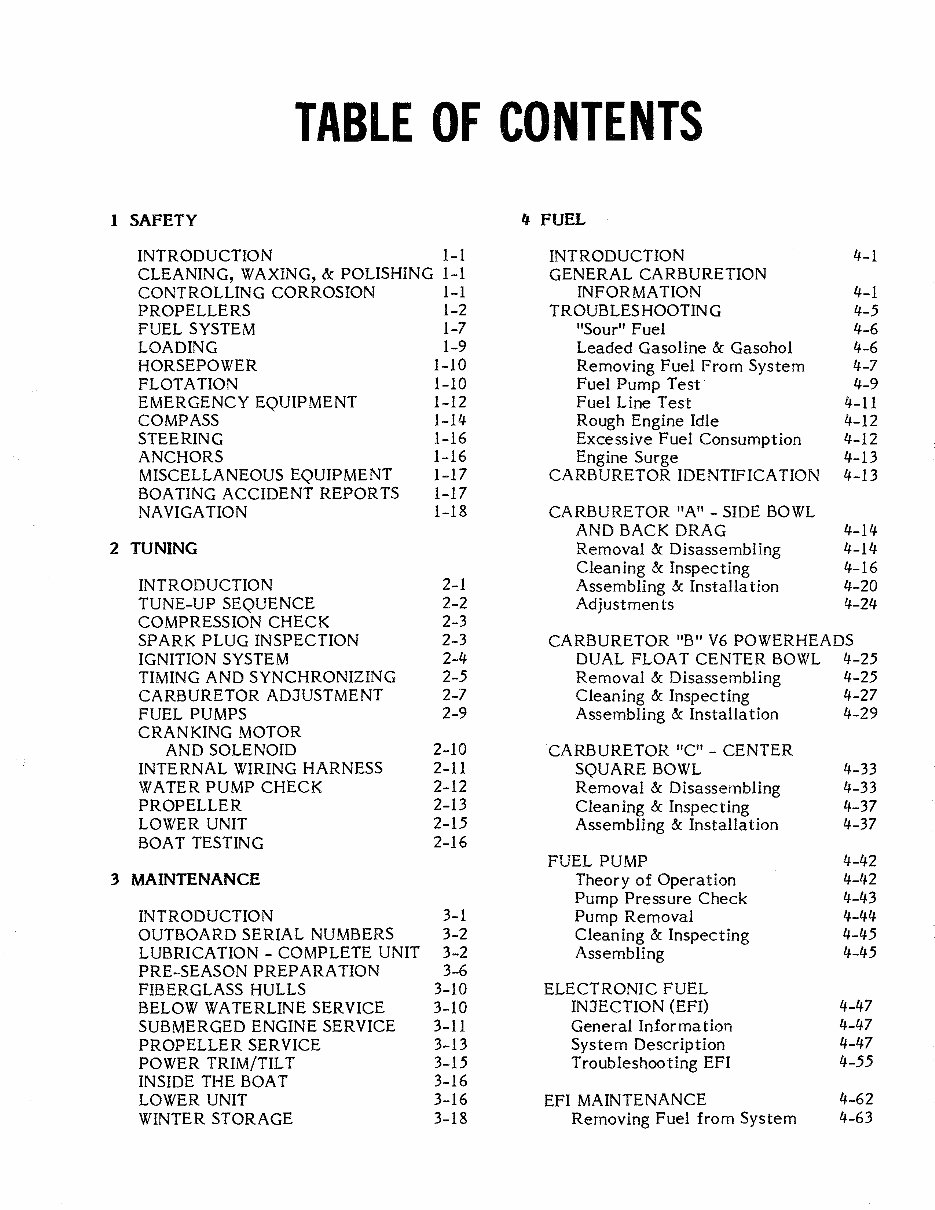
TABLE OF CONTENTS 1 SAFETY II FUEL INTRODUCTION 1-1 INTRODUCTION 4-1 CLEANING, WAXING, &. POLISHING 1-1 GENERAL CARBURETION CONTROLLING CORROSION 1-1 INFORMATION 4-1 PROPELLERS 1-2 TROUBLESHOOTING 4-5 FUEL SYSTEM 1-7 "Sour" Fuel 4-6 LOADING 1-9 Leaded Gasoline & Gasohol 4-6 HORSEPOWER 1-10 Removing Fuel From System 4-7 FLOTATION 1-10 Fuel Pump Test 4-9 EMERGENCYEQUWMENT 1-12 Fuel Line Test 4-11 COMPASS 1-14 Rough Engine Idle 4-12 STEERING 1-16 Excessive Fuel Consumption 4-12 ANCHORS 1-16 Engine Surge 4-13 MISCELLANEOUS EQUIPMENT 1-17 CARBURETOR IDENTIFICATION 4-13 BOATING ACCIDENT REPORTS 1-17 NAVIGATION 1-18 CARBURETOR "A" - SIDE BOWL AND BACK DRAG 4-14 2 TUNING Removal & Disassembling 4-14 Cleaning & Inspecting 4-16 INTRODUCTION 2-1 Assembling &. Installation 4-20 TUNE-UP SEQUENCE 2-2 Adjustmen ts 4-24 COMPRESSION CHECK 2-3 SPARK PLUG INSPECTION 2-3 CARBURETOR "B" V6 POWERHEADS IGNITION SYSTEM 2-4 DUAL FLOAT CENTER BOWL 4-25 TIMING AND SYNCHRONIZING 2-5 Removal & Disassembling 4-25 CARBURETOR ADJUSTMENT 2-7 Cleaning & Inspecting 4-27 FUEL PUMPS 2-9 Assembling & Installation 4-29 CRANKING MOTOR AND SOLENOID 2-10 CARBURETOR'~"-CENTER INTERNAL WIRING HARNESS 2-11 SQUARE BOWL 4-33 WATER PUMP CHECK 2-12 Removal & Disassembling 4-33 PROPELLER 2-13 Cleaning & Inspecting 4-37 LOWER UNIT 2-15 Assembling &. Installation 4-37 BOAT TESTING 2-16 FUEL PUMP 4-42 3 MAINTENANCE Theory of Operation 4_IJ2 Pump Pressure Check 4-43 INTRODUCTION 3-1 Pump Removal 4-44 OUTBOARD SERIAL NUMBERS 3-2 Cleaning & Inspecting 4-45 LUBRICATION - COMPLETE UNIT 3-2 Assembling 4-45 PRE-SEASON PREPARATION 3-6 FIBERGLASS HULLS 3-10 ELECTRONIC FUEL BELOW WATERLINE SERVICE 3-10 INJECTION (EFI) 4-47 SUBMERGED ENGINE SERVICE 3-11 General Infor ma tion 4-47 PROPELLER SERVICE 3-13 System Description 4-47 POWER TRIM/TILT 3-15 Troubleshooting EFI 4-55 INSIDE THE BOAT 3-16 LOWER UNIT 3-16 EFI MAINTENANCE 4-62 WINTER STORAGE 3-18 Removing Fuel from System 4-63
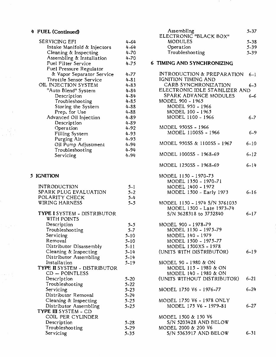
4 FUEL (Continued) Assembling 5-37 ELECTRONIC "BLACK BOX" SERVICING EFI 4-64 MODULES 5-38 Intake Manifold &: Injectors 4-64 Operation 5-39 Cleaning &: Inspecting 4-70 Troubleshooting 5-39 Assembling &: Installation 4-70 Fuel Filter Service 4-75 6 TIMING AND SYNCHRONIZING Fuel Pressure Regulator &: Vapor Separator Service 4-77 INTRODUCTION &: PREPARATION 6-1 Throttle Sensor Service 4-81 IGNITION TIMING AND OIL INJECTION SYSTEM 4-83 CARB SYNCHRONIZATION 6-3 "Auto Blend" System 4-84 ELECTRONIC IDLE STABILIZER AND Description 4-84 SPARK ADVANCE MODULES 6-6 Troubleshooting 4-85 MODEL 900 - 1965 Storing the System 4-88 MODEL 950 - 1966 Prep. for Use 4-88 MODEL 100 - 1965 Advanced Oil Injection 4-89 MODEL 1100 - 1966 6-7 Description 4-89 Operation 4-92 MODEL 950SS - 1966 Filling System 4-93 MODEL 1100SS - 1966 6-9 Purging Air 4-93 Oil Pump Adjustment 4-94 MODEL 950SS &: 1100SS - 1967 6-10 Troubleshooting 4-94 Servicing 4-94 MODEL 1000SS - 1968-69 6-12 MODEL 1250SS - 1968-69 6-14 5 IGNITION MODEL 1150 - 1970-73 MODEL 1350 - 1970-71 INTRODUCTION 5-1 MODEL 1400 - 1972 SPARK PLUG EVALUATION 5-2 MODEL 1500 - Early 1973 6-16 POLARITY CHECK 5-4 WIRING HARNESS 5-5 MODEL 1150 - 1974 SIN 3761035 MODEL 1500 - Late 1973-74 TYPE I SYSTEM - DISTRIBUTOR SIN 3628318 to 3752840 6-17 WITH POINTS Description 5-5 MODEL 900 - 1978-79 Troubleshooting 5-7 MODEL 1150 - 1975-79 Servicing 5-10 MODEL 140 - 1979 Removal 5-10 MODEL 1500 - 1975-77 Distributor Disassembly 5-11 MODEL 1500XS - 1978 Cleaning &: Inspecting 5-14 (UNITS WITH DISTRIBUTOR) 6-19 Distributor Assembling 5-14 Installa tion 5-19 MODEL 90 - 1980 &: ON TYPE n SYSTEM - DISTRIBUTOR MODEL 115 - 1980 &: ON CD - POINTLESS MODEL 140 - 1980 &: ON Description 5-20 (UNITS WITHOUT DISTRIBUTOR) 6-21 Troubleshooting 5-22 Servicing 5-23 MODEL 1750 V6 - 1976-77 6-24 Distributor Removal 5-24 Cleaning &: Inspecting 5-25 MODEL 1750 V6 -1978 ONLY Distributor Assembling 5-25 MODEL 175 V6 - 1979-81 6-27 TYPE In SYSTEM - CD COIL PER CYLINDER MODEL 1500 &: 150 V6 Description 5-28 SIN 5203428 AND BELOW Troubleshooting 5-29 MODEL 2000 &: 200 V6 Servicing 5-35 SIN 5363917 AND BELOW 6-31
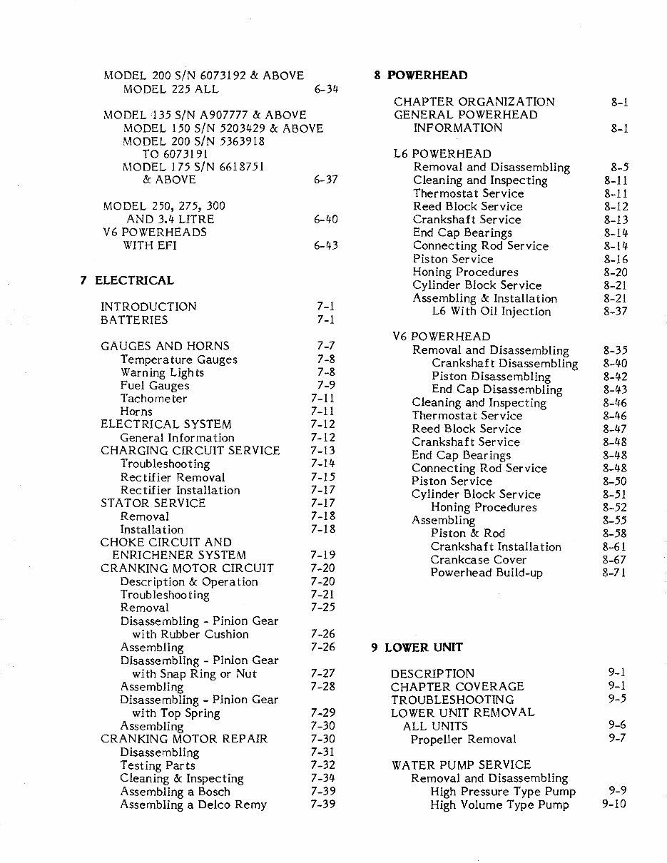
MODEL 200 SiN 6073192 & ABOVE 8 POWERHEAD MODEL 225 ALL 6-34- CHAPTER ORGANIZATION 8-1 MODEL 135 SIN A907777 & ABOVE GENERALPOWERHEAD MODEL 150 SiN 5203429 & ABOVE INFORMA TION 8-1 MODEL 200 SIN 5363918 TO 6073191 L6 POWERHEAD MODEL 175 SIN 6618751 Removal and Disassembling 8-5 & ABOVE 6-37 Cleaning and Inspecting 8-11 Thermostat Service 8-11 MODEL 250, 275, 300 Reed Block Service 8-12 AND 3.4- LITRE 6-40 Crankshaft Service 8-13 V6 POWERHEADS End Cap Bearings 8-14 WITH EFI 6-43 Connecting Rod Service 8-14 Piston Service 8-16 Honing Procedures 8-20 7 ELECTRICAL Cylinder Block Service 8-21 Assembling &: Installation 8-21 INTRODUCTION 7-1 L6 With Oil Injection 8-37 BATTERIES 7-1 V6 POWERHEAD GAUGES AND HORNS 7-7 Removal and Disassembling 8-35 Temperature Gauges 7-8 Crankshaft Disassembling 8-40 Warn ing Ugh ts 7-8 Piston Disassembling 8-42 Fuel Gauges 7-9 End Cap Disassembling 8-43 Tachometer 7-11 Cleaning and Inspecting 8-46 Horns 7-11 Thermostat Service 8-46 ELECTRICAL SYSTEM 7-12 Reed Block Service 8-47 General Information 7-12 Crankshaft Service 8-48 CHARGING CIRCUIT SERVICE 7-13 End Cap Bearings 8-48 Troubleshooting 7-14 Connecting Rod Service 8-48 Rectifier Removal 7-15 Piston Service 8-50 Rectifier Installation 7-17 Cylinder Block Service 8-51 STATOR SERVICE 7-17 Honing Procedures 8-52 Removal 7-18 Assembling 8-55 Installa t ion 7-18 Piston &: Rod 8-58 CHOKE CIRCUIT AND Crankshaft Installation 8-61 ENRICHENER SYSTEM 7-19 Crankcase Cover 8-67 CRANKING MOTOR CIRCUIT 7-20 Powerhead Build-up 8-71 Description & Operation 7-20 Troubleshooting 7-21 Removal 7-25 Disassembling - Pinion Gear with Rubber Cushion 7-26 Assembling 7-26 9 LOWER UNIT Disassembling - Pinion Gear with Snap Ring or Nut 7-27 DESCRIPTION 9-1 Assembling 7-28 CHAPTER COVERAGE 9-1 Disassembling - Pinion Gear TROUBLESHOOTING 9-5 with Top Spring 7-29 LOWER UNIT REMOVAL Assembling 7-30 ALL UNITS 9-6 CRANKING MOTOR REPAIR 7-30 Propeller Removal 9-7 Disassembling 7-31 Testing Parts 7-32 WATER PUMP SERVICE Cleaning &: Inspecting 7-34 Removal and Disassembling Assembling a Bosch 7-39 High Pressure Type Pump 9-9 Assembling a Delco Remy 7-39 High Volume Type Pump 9-10
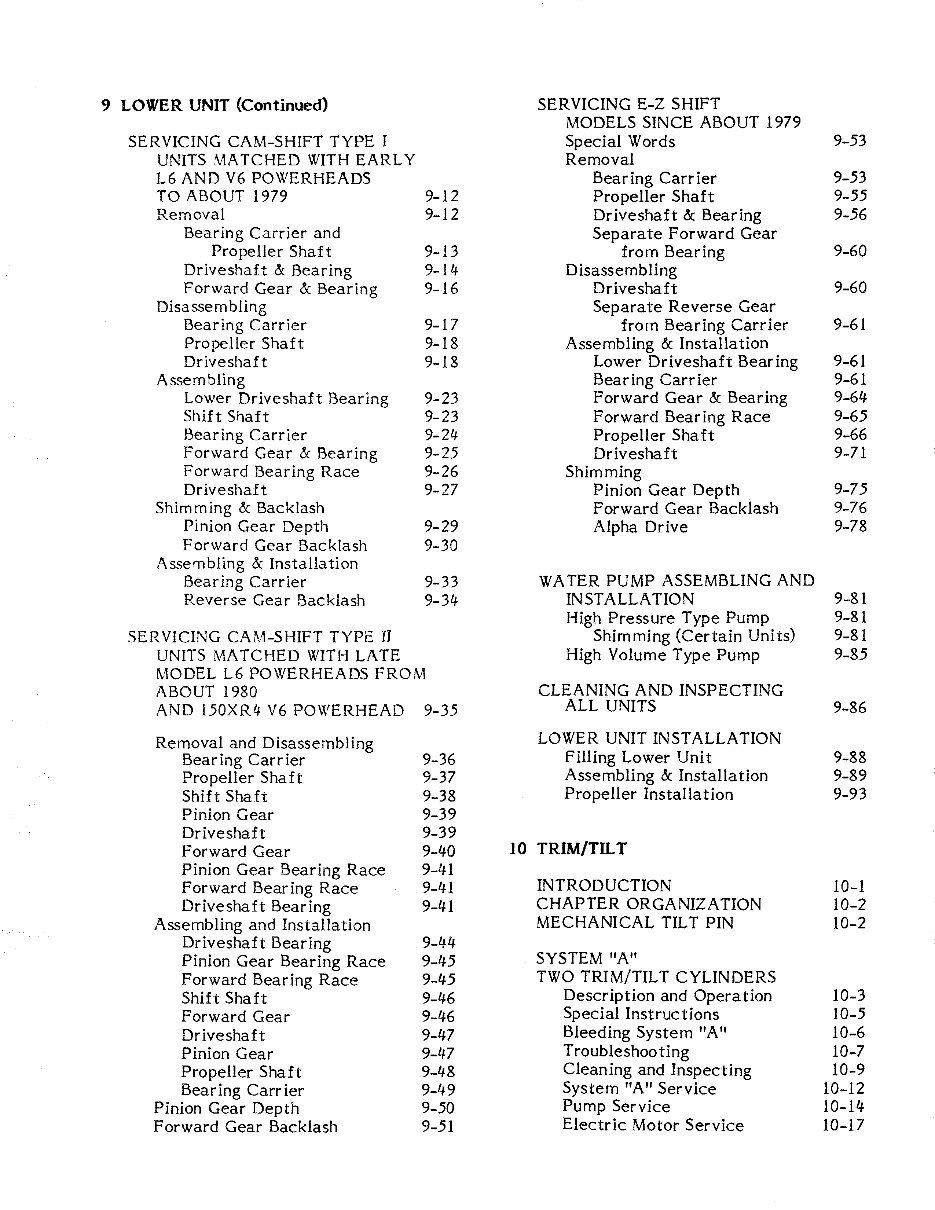
9 LOWER UNIT (Continued) SERVICING E-Z SHIFT MODELS SINCE ABOUT 1979 SERVICING CAM-SHIFT TYPE I Special Words 9-53 UNITS ;\1ATCHED WITH EARLY Removal L6 AND V6 POWERHEADS Bearing Carrier 9-53 TO ABOUT 1979 9-12 Propeller Shaft 9-55 Removal 9-12 Driveshaft & Bearing 9-56 Bearing Carrier and Separa te Forward Gear Propeller Shaft 9-13 from Bearing 9-60 Driveshaft & Bearing 9-ll/. Disassembling Forward Gear & Bearing 9-16 Driveshaft 9-60 Disassem bUng Separate Reverse Gear Bearing Carrier 9-17 from Bearing Carrier 9-61 Propeller Shaft 9-18 Assembling & Installation Driveshaft 9-18 Lower Driveshaft Bearing 9-61 Assembling Bearing Carrier 9-61 Lower Driveshaft Bearing 9-23 Forward Gear & Bearing 9-64 Shift Shaft 9-23 Forward Bear ing Race 9-65 Bearing Carrier 9-24 Propeller Shaft 9-66 Forward Gear & Bearing 9-25 Driveshaft 9-71 Forward Bear ing Race 9-26 Shimming Driveshaft 9-27 Pinion Gear Depth 9-75 Shimming & Backlash Forward Gear Backlash 9-76 Pinion Gear Depth 9-29 Alpha Drive 9-78 Forward Gear Backlash 9-30 Assembling & Installation Bearing CarrIer 9-33 WATER PUMP ASSEMBLING AND Reverse Gear Backlash 9-34 INSTALLATION 9-81 High Pressure Type Pump 9-81 SERVICING CAM-SHIFT TYPE II Shimming (Certain Units) 9-81 UNITS MATCHED WITH LATE High Volume Type Pump 9-85 MODEL L6 POWERHEADS FROM ABOUT 1980 CLEANING AND INSPECTING AND 150XR4 V6 POWERHEAD 9-35 ALL UNITS 9-86 Removal and Disassembling LOWER UNIT INSTALLATION Bearing Carrier 9-36 Filling Lower Unit 9-88 Propeller Shaft 9-37 Assembling & Installation 9-89 Shift Shaft 9-38 Propeller Installation 9-93 Pinion Gear 9-39 Driveshaft 9-39 Forward Gear 9-40 10 TRIM/TILT Pinion Gear Bearing Race 9-41 Forward Bearing Race 9-41 INTRODUCTION 10-1 Driveshaft Bearing 9-41 CHAPTER ORGANIZATION 10-2 Assembling and Installation MECHANICAL TILT PIN 10-2 Driveshaft Bearing 9-44 Pinion Gear Bearing Race 9-45 SYSTEM "A" Forward Bearing Race 9-45 TWO TRIM/TILT CYLINDERS Shift Shaft 9-46 Description and Operation 10-3 Forward Gear 9-46 Special Instructions 10-5 Driveshaft 9-47 Bleeding System "A" 10-6 Pinion Gear 9-47 Troubleshooting 10-7 Propeller Shaft 9-48 Cleaning and Inspecting 10-9 Bear ing Carr ier 9-49 System "A" Service 10-12 Pinion Gear Depth 9-50 Pump Service 10-14 Forward Gear Backlash 9-51 Electric Motor Service 10-17
SYSTEM "B" CARBURETOR JET SIZE/ELEVATION TWO TRIM CYLINDERS CHARTS A-13 ONE TILT CYLINDER PISTON AND CYLINDER SPECS. A-19 Description and Operation 10-21 REED STOP OPENING A-20 Bleeding System "B" 10-22 LOWER UNIT OIL CAPACITY Flushing 10-23 AND GEAR CHART A-21 Troubleshooting 10-24 LOWER UNIT BACKLASH TABLE A-22 System "B" Service 10-31 TORQUE VALUE SPECIFICATIONS A-23 Preliminary Tasks 10-31 Removal 10-33 WIRE IDENTIFICATION DWGS. Component Service 10-34 L6 Models 900, 950, 1000 Manual Release Valve 10-34 and 1100 -- 1965-66 A-24 Oil Reservoir Cover 10-35 L6 Models 950, 1000, 1100, Trim Cylinder 10-35 and 1250 -- 1967-69 A-25 Tilt Cylinder 10-36 L6 Models 1150, 1350, 1400 Electric Motor 10-36 and 1500 -- 1970-78 A-26 Cleaning and Inspecting 10-37 L6 Models 900, 1150, Assembling & Installation 10-38 and 1500 -- 1976-78 A-27 L6 Models 90, 115, SYSTEM "C" and 140 -- 1979 only A-28 ONE TRIM/TILT CYLINDER V6 Models SIN 4301235 Description and Operation 10-53 to 5129480 A-29 Bleeding System "C" 10-54 V6 Models 150, 175 & 200 Troubleshooting 10-54 SIN 5129481 to 5363918 A-30 System "C" Service 10-55 Pump Removal & Service 10-55 V6 Models 150, 175, & 200 Cylinder Service 10-55 SIN 5363919 to 5464484 A-32 V6 Models 150, 175, & 200 SIN 5464 1 185 to C 100860 A-34 11 REMOTE CONTROLS V6 Model 225 SIN 5615282 and higher A-36 INTRODUCTION 11-1 V6 Models with 74 0 block A-38 STEERING SYSTEMS 11-1 L6 Models 90, 115, & DIRECTIONAL INDICATOR 11-2 140 -- 1980-89 A-40 ROTARY STEERING SERVICE 11-5 V6 Models 135, 150, and 175 Disassembling 11-5 SIN CI00861 & higher A-4l Cleaning & Inspecting 11-5 V6 Model l50XR4 Assembling 11-6 with 40-amp stator A-42 V6 Model 200 WITHOUT EFI STANDARD RIDE GUIDE KIT 11-8 SIN C100861 & higher A-43 CUSTOM RIDE GUIDE KITS 11-8 V6 Model 220 XRi WITH EFI A-44 MER CONTROL PANEL V6 Model 200 XRi WITH EFI A-45 EARLY MODEL 11-9 Early V6 remote control WITH Disassembling 11-9 temperature horn A-46 Assembling 11-12 Early remote control WITH power trim/tilt A-47 COMMANDER CONTROL BOX "Commander" side mount con troIs Removal & Disassembling 11-13 WITHOUT power tr im A-48 Cleaning & Inspecting 11-20 "Commander" side mount controls Assembling & Installation 11-22 WITH power trim/til t CABLE ADJUSTMENTS 11-31 and WITHOUT warning horn A- l 19 "Commander" side mount controls APPENDIX WITH warning horn to 1989 A-50 METRIC CONVERSION CHART A-I "Commander" side mount controls ENGINE SPECIFICATIONS WITH warning horn AND TUNE-UP ADJUSTMENTS A-3 1989 and on A-51
WIRE IDENTIFICATION (Continued) Type "A" power trim/tilt system -- two trim/tilt cylinders -- with OLD style "Commander" side mount controls single solenoid A-62 WITH trim indicator gauge Type "A" power trim/tilt and trim sender A-52 system -- two trim/tilt Panel mount con trol A-53 cylinders -- with NEW style Tachometer WITHOUT adjustable single solenoid A-63 dial, trim indicator gauge, Type "A" power trim/ tilt and alarm horn A-54 system -- two trim/til t Tachometer WITH adjustable dial, cylinders -- with DUAL tr im indica tor gauge and solenoids A-64 temperature gauge -- Model Type "B" power trim/tilt 200 &. 220 WITH EFI only A-55 system -- two trim cylinders Instrument panel -- single outboard and one tilt cylinder A-65 installation using "Commander" Type "c" power trim/tilt 2000 remote control A-56 system -- WITHOUT fuse -- Visual warning system single cylinder -- installation A-57 pump mounted in boat A-66 Oil level gauge installation A-58 Type "c" power trim/tilt Dual outboard synchronizer system -- WITH fuse -- system A-59 single cylinder -- pump Dual outboard instrument mounted in boat A-67 setup for PORT Type "c" power trim/ tilt outboard uni t A-60 system WITH fuse -- Dual outboard instrument 1990 and on A-68 setup for STARBOARD Trim indicator gauge outboard unit A-61 and alar m horn A-69
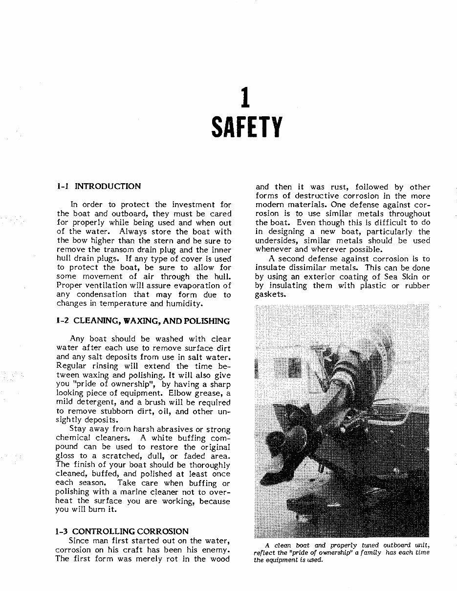
1 SAFETY 1-1 INTRODUCTION In order to protect the investment for the boat and outboard, they must be cared for properly while being used and when out of the water. Always store the boat with the bow higher than the stern and be sure to remove the transom drain plug and the inner hull drain plugs. If any type of cover is used to protect the boat, be sure to allow for some movement of air through the hull. Proper ventilation will assure evaporation of any condensation that may form due to changes in temperature and humidity. 1-2 CLEANING, WAXING, AND POLISHING Any boat should be washed with clear water after each use to remove surface dirt and any salt deposits from use in salt water. Regular rinsing will extend the time be- tween waxing and polishing. It will also give you "pride of ownership", by having a sharp looking piece of equipment. Elbow grease, a mild detergent, and a brush will be required to remove stubborn dirt, oil, and other un- sigh tly deposi ts. Stay away from harsh abrasives or strong chemical cleaners. A white buffing com- pound can be used to restore the original gloss to a scratched, dull, or faded area. The finish of your boat should be thoroughly cleaned, buffed, and polished at least once each season. Take care when buffing or polishing with a marine cleaner not to over- hea t the surface you are working, because you will burn it. 1-3 CONTROLLING CORROSION Since man first started out on the water, corrosion on his craft has been his enemy. The first form was merely rot in the wood and then it was rust, followed by other forms of destructive corrosion in the more modern materials. One defense against cor- rosion is to use similar metals throughout the boat. Even though this is difficult to do in designing a new boat, particularly the undersides, similar metals should be used whenever and wherever possible. A second defense against corrosion is to insulate dissimilar metals. This can be done by using an exterior coating of Sea Skin or by insulating them with plastic or rubber gaskets. A clean boat and properly tuned outboard unit, reflect the "pride of ownership" a family has each time the equipment is used.
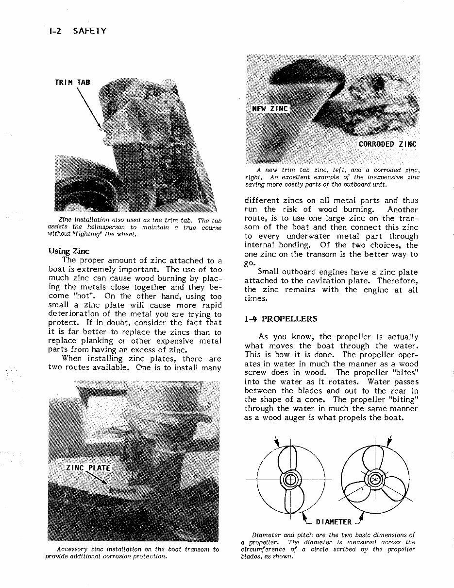
1-2 SAFETY Zinc installation also used as the trim tab. The tab assists the helmsperson to maintain a true course without "fighting" the wheel. Using Zinc The proper amount of zinc attached to a boat is extremely important. The use of too much zinc can cause wood burning by plac- ing the metals close together and they be- come "hot". On the other hand, using too small a zinc plate will cause more rapid deterioration of the metal you are trying to protect. If in doubt, consider the fact that it is far better to replace the zincs than to replace planking or other expensive metal parts from having an excess of zinc. When installing zinc plates, there are two routes available. One is to install many Accessory zinc installation on the boat transom to provide additional corrosion protection. A new trim tab zinc, left, and a corroded zinc, right. An excellent example of the inexpensive zinc saving more costly parts of the outboard unit. different zincs on all metal parts and thus run the risk of wood burning. Another route, is to use one large zinc on the tran- som of the boat and then connect this zinc to every underwater metal part through internal bonding. Of the two choices, the one zinc on the transom is the better way to go. Small outboard engines have a zinc plate attached to the cavitation plate. Therefore, the zinc remains with the engine at all times. 1-'1 PROPELLERS As you know, the propeller is actually what moves the boat through the water. This is how it is done. The propeller oper- ates in water in much the manner as a wood screw does in wood. The propeller "bites" into the water as it rotates. Water passes between the blades and out to the rear in the shape of a cone. The propeller "biting" through the water in much the same manner as a wood auger is what propels the boat. Diameter and pitch are the two basic dimensions of a propeller. The diameter is measured across the circumference of a circle scribed by the propeller blades, as shown.
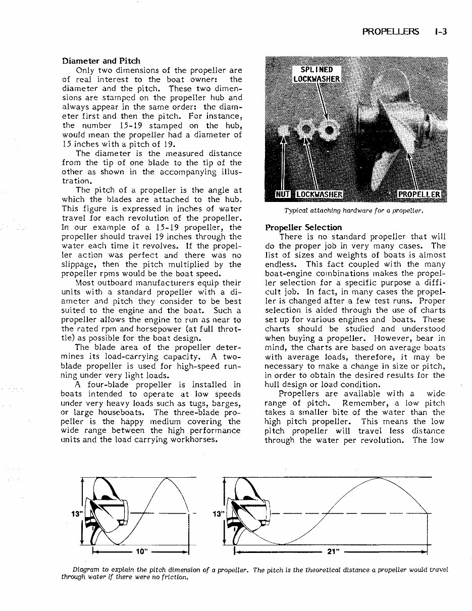
Diameter and Pitch Only two dimensions of the propeller are of real interest to the boat owner: the diameter and the pitch. These two dimen- sions are stamped on the propeller hub and always appear in the same order: the diam- eter first and then the pitch. For instance, the number 15-19 stamped on the hub, would mean the propeller had a diameter of 15 inches with a pitch of 19. The diameter is the measured distance from the tip of one blade to the tip of the other as shown in the accom panying illus- tration. The pitch of a propeller is the angle at which the blades are attached to the hub. This figure is expressed in inches of water travel for each revolution of the propeller. In our example of a 15-19 propeller, the propeller should travel 19 inches through the water each time it revolves. If the propel- ler action was perfect and there was no slippage, then the pitch multiplied by the propeller rpms would be the boat speed. Most outboard manufacturers equip their units with a standard propeller with a di- ameter and pitch they consider to be best suited to the engine and the boat. Such a propeller allows the engine to run as near to the rated rpm and horsepower (at full throt- tle) as possible for the boat design. The blade area of the propeller deter- mines its load-carrying capacity. A two- blade propeller is used for high-speed run- ning under very light loads. A four-blade propeller is installed in boats intended to operate at low speeds under very heavy loads such as tugs, barges, or large house boa ts. The three-blade pro- peller is the happy medium covering the wide range between the high performance units and the load carrying workhorses. 1-+--- 10" --_~ PROPELLERS 1-3 Typical attaching hardware for a propeller. Propeller Selection There is no standard propeller that will do the proper job in very many cases. The list of sizes and weights of boats is almost endless. This fact coupled with the many boat-engine combinations makes the propel- ler selection for a specific purpose a diffi- cult job. In fact, in many cases the propel- ler is changed after a few test runs. Proper selection is aided through the use of charts set up for various engines and boats. These charts should be studied and understood when buying a propeller. However, bear in mind, the charts are based on average boats with average loads, therefore, it may be necessary to make a change in size or pitch, in order to obtain the desired results for the hull design or load condition. Propellers are available with a wide range of pitch. Remember, a low pitch takes a smaller bite of the water than the high pitch propeller. This means the low pitch propeller will travel less distance through the water per revolution. The low 21" -------~ Diagram to explain the pitch dimension of a propeller. The pitch is the theoretical distance a propeller would travel through water if there were no friction.
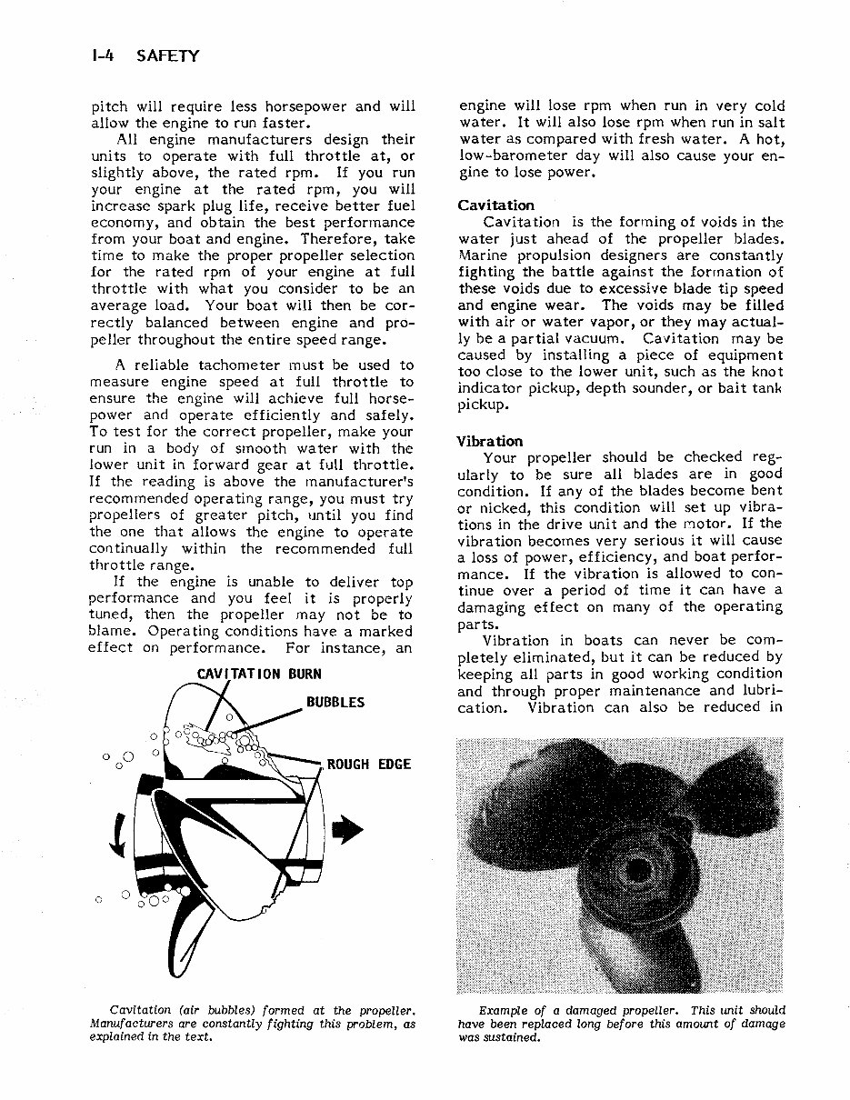
1-4 SAFETY pitch will require less horsepower and will allow the engine to run faster. All engine manufacturers design their units to operate with full throttle at, or slightly above, the rated rpm. If you run your engine at the rated rpm, you will increase spark plug life, receive better fuel economy, and obtain the best performance from your boat and engine. Therefore, take time to make the proper propeller selection for the rated rpm of your engine at full throttle with what you consider to be an average load. Your boat will then be cor- rectly balanced between engine and pro- peller throughout the entire speed range. A reliable tachometer must be used to measure engine speed at full throttle to ensure the engine will achieve full horse- power and operate efficiently and safely. To test for the correct propeller, make your run in a body of smooth water with the lower unit in forward gear at full throttle. If the reading is above the manufacturer's recommended operating range, you must try propellers of greater pitch, until you find the one that allows the engine to operate continually within the recommended full throttle range. If the engine is unable to deliver top performance and you feel it is properly tuned, then the propeller may not be to blame. Operating conditions have a marked effect on performance. For instance, an o o 0 o Cavitation (air bubbles) formed at the propeller. Manufacturers are constantly fighting this problem, as explained in the text. engine will lose rpm when run in very cold water. It will also lose rpm when run in salt water as compared with fresh water. A hot, low-barometer day will also cause your en- gine to lose power. Cavitation Cavitation is the forming of voids in the water just ahead of the propeller blades. Marine propulsion designers are constantly fighting the battle against the formation of these voids due to excessive blade tip speed and engine wear. The voids may be filled with air or water vapor, or they may actual- ly be a partial vacuum. Cavitation may be caused by installing a piece of equipment too close to the lower unit, such as the knot indica tor pickup, depth sounder, or bai t tan~ pickup. Vibration Your propeller should be checked reg- ularly to be sure all blades are in good condition. If any of the blades become bent or nicked, this condition will set up vibra- tions in the drive unit and the Motor. If the vibration becomes very serious it will cause a loss of power, efficiency, and boat perfor- mance. If the vibration is allowed to con- tinue over a period of time it can have a damaging effect on many of the operating parts. Vibration in boats can never be com- pletely eliminated, but it can be reduced by keeping all parts in good working condition and through proper maintenance and lubri- cation. Vibration can also be reduced in Example of a damaged propeller. This unit should have been replaced long before this amount of damage was sustained.
The Mercury Mariner 125 HP 2-stroke Factory Service Repair Manual is a comprehensive resource for repairing and adjusting your Mercury Mariner 125 HP 2-stroke engine. It is designed to be a valuable reference for both professional mechanics and DIY enthusiasts. The manual provides detailed explanations for installation, removal, disassembly, assembly, repair, and check procedures, presented in a clear and sequential order.
Serial Numbers: US 0D283222 and above, Belgium 09793577 and above
This manual is known by various names, including:
Mercury Mariner 125 HP 2-stroke service manual
Mercury Mariner 125 HP 2-stroke repair manual
Mercury Mariner 125 HP 2-stroke workshop manual
Mercury Mariner 125 HP 2-stroke shop manual
All the above manuals are one and the same.
Upon purchase, you will have immediate access to the manual, which is divided into chapters. The manual index includes:
Important information
Electrical
Fuel system
Powerhead
Mid-section
Lower unit
Attachments/control linkage
Manual starter
Each chapter is further divided into sections, with each section containing sub-sections. The manual includes exploded diagrams at the beginning of each removal and disassembly section to aid in identifying parts and clarifying procedure steps. The manual is available in PDF format, allowing for easy printing of specific pages or the entire manual.
Recently Viewed
5,521,897Happy Clients
2,594,462eManuals
1,120,453Trusted Sellers
15Years in Business
Price:
Actual Price:
Mercury Mariner 125 HP 2-stroke Factory Service Repair Manual