1-1 90-13645--2 1095 GENERAL INFORMATION AND SPECIFICATIONS General Specification NOTE: Other specification (torques, etc.) are listed in the respective sections. Model 70 Model 75 Model 80 Model 90 Horsepower 70 (52.2 kw) 75 (55.9 kw) 80 (59.6 kw) 90 (67.1 kw) Idle RPM (in forward gear) 650 - 700 Full Throttle RPM Range 4750 - 5250 5000 - 5500 Piston Replacement 71.12 (1165.7cc) Cylinder Bore 3.375 (85.7mm) Stroke 2.65 (67.3mm) Engine Type 3 Cylinder, 2 Cycle Ignition Type C.D. Breakerless Recommended Spark Plug NGK-BUHW-2 or AC-V40 FFK or Champion L78V Inductor Plugs: NGK-BUZHW-2 or Champion QL78V Cylinder Firing Order 1-3-2 Recommended Power Trim Fluid Quicksilver Power Trim & Steering Fluid or Automotive Transmission Fluid (ATF) Type F, FA or Dexron II Recommended Gasoline Regular Leaded, Premium, Low-Lead and Lead-Free automotive gaso- lines with a minimum pump posted octane rating of 86 Recommended Oil Quicksilver TC-WII or TC-W3 2-Cycle Outboard Oil Engine Weight ELO ELOPT 260 lbs. 280 lbs. Fuel Tank Capacity 6.6 U.S. Gallons (5 Imp. Gals.; 25 Liters) Gear Housing Lubricant Capacity 22.5 fl. oz. (665.3ml) Gasoline/Oil Ratio at Idle 80:1 Gasoline/Oil Ratio at W.O.T. 50:1 Gear Ratio 2.3:1 Oil Injection Tank Capacity Tank Capacity 1 gal. (3.78 liter) Maximum operation per tank full of oil at W.O.T. 6 hours Oil remaining when warning buzzer sounds 1 qt. (.95 liter) Operating time remaining at wide open throttle when warn- ing buzzer sounds 1 Hour
1-2 90-13645--2 1095 GENERAL INFORMATION AND SPECIFICATIONS General Specification (continued) NOTE: Other specification (torques, etc.) are listed in the respective sections. Model 100 Model 115 Horsepower 100 (74.6 kw) 115 (85.8 kw) Idle RPM (in forward gear) 650 - 700 Full Throttle RPM Range 4750 - 5250 Piston Replacement 105 (1720.9cc) Cylinder Bore 3.375 (85.7mm) Stroke 2.930 (74.4mm) Engine Type 4 Cylinder, 2 Cycle Ignition Type C.D. Breakerless Recommended Spark Plug NGK-BPH8H-N-10* Gap - 0.040 in. (1.0mm) Inductor Plug NGK BPZ 8H-N-10* Gap - 0.040 in. (1.0mm) NGK-BUHW Cylinder Firing Order 1-3-2-4 Recommended Power Trim Fluid Quicksilver Power Trim & Steering Fluid or Automotive Transmission Fluid (ATF) Type F, FA or Dexron II Recommended Gasoline Regular Leaded, Premium, Low-Lead and Lead-Free automotive gaso- lines with a minimum pump posted octane rating of 86 Recommended Oil Quicksilver 2-Cycle Outboard Oil Engine Weight ELO ELOPT 340 lbs. 360 lbs. Fuel Tank Capacity 6.6 U.S. Gallons (5 Imp. Gals.; 25 Liters) Gear Housing Lubricant Capacity 22.5 fl. oz. (665.2ml) Gasoline/Oil Ratio at Idle 80:1 Gasoline/Oil Ratio at W.O.T. 50:1 Gear Ratio 2.07:1 Oil Injection Tank Capacity Tank Capacity 1.4 gal. (5.3 liters) Maximum operation per tank full of oil at W.O.T. 5 hours Oil remaining when warning buzzer sounds 1 qt. (.95 liter) Operating time remaining at wide open throttle when warn- ing buzzer sounds 50 min. approx. *Improves running quality between 1800 – 2000 RPM.
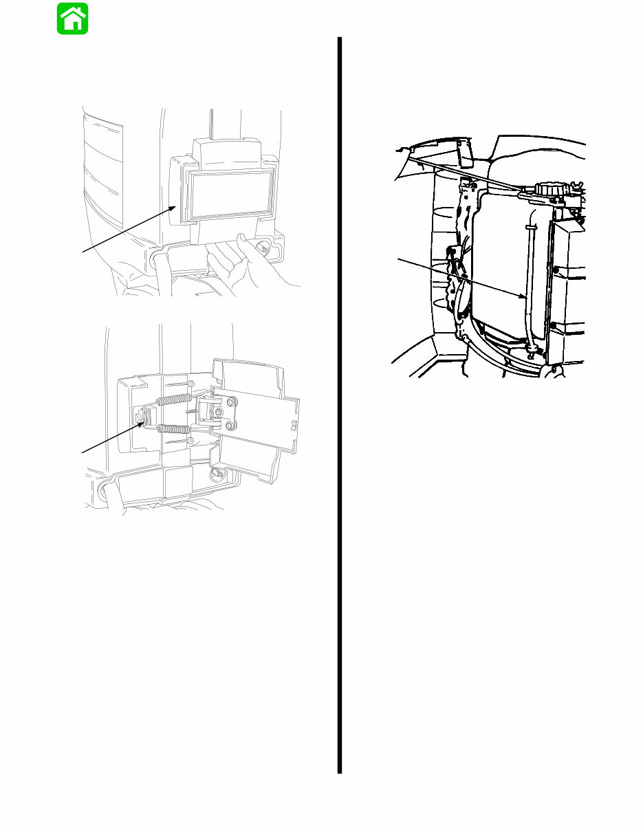
90-13645--2 495 1-3 GENERAL INFORMATION AND SPECIFICATIONS Cowl Removal Pull outward on starboard side of front shield (a). Remove spring (b) from latch and open cowls. 18291 a 18292 b Filling Oil Injection System Open starboard cowl (refer to cowl removal on this page). Some earlier outboards will have a cowl brack- et to hold cowl open as shown. Fill tank with recommended oil. a a - Oil Tank Tube
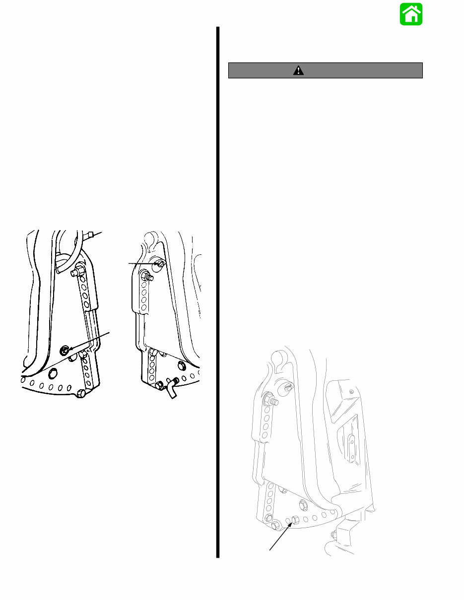
1-4 90-13645--2 495 GENERAL INFORMATION AND SPECIFICATIONS Power Trim System GENERAL INFORMATION The power trim system is filled at the manufacturer and is ready for use. Trim outboard through entire trailering range several times to remove any air from the system. The trim system is pressurized and is not externally vented. The outboard can be raised or lowered manu- ally by loosening the manual release valve four turns. The trim “out” angle of this outboard is not adjustable. The trim system has an internal valve which will automatically stop the outward trim travel at 20_ when engine RPM is approximately 2000 RPM or higher; outboard also has to be in water and in gear. The outboard can be operated beyond the 20_ trim limit for operating outboard in shallow water if engine RPM is kept below approximately 2000 RPM. a b 23321 a - Fill Screw (System is Pressurized, DO NOT Open Unless Outboard is Tilted to Full Up Position) b - Manual Release Valve Trim “In” Angle Adjustment MODELS WITH POWER TRIM WARNING Operating some boats with outboard trimmed to the full “in” trim angle [not using trim adjustment bolt (a)] at planing speed will cause undesirable and/or unsafe steering conditions. Each boat MUST BE water tested for handling characteristics after outboard installation and after any trim adjust- ments. IMPORTANT: Some boat/motor combinations, that do not use the trim adjustment bolt (a) and are trimmed to the full “in” trim angle, will not experi- ence any undesirable and/or unsafe steering conditions during planing speed. Thus, not using trim adjustment bolt may be desired. However, some boats with outboard trimmed to the full “in” trim angle at planing speeds will cause undesir- able and/or unsafe steering conditions. If these steering conditions are experienced, under no circumstances should the outboard be operated without the trim adjustment bolt and without the bolt adjusted in the proper holes to prevent un- safe handling characteristics. Water test the boat not using the trim adjustment bolt. If undesirable and/or unsafe steering conditions are experienced (boat runs with nose down), install trim adjustment bolt in proper hole to prevent unsafe han- dling characteristics. 22744 a
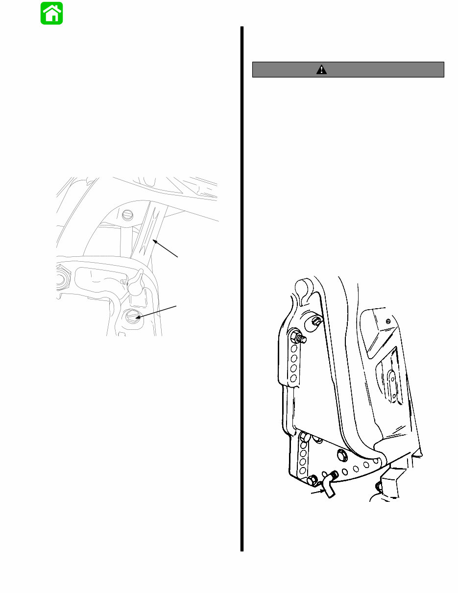
90-13645--2 495 1-5 GENERAL INFORMATION AND SPECIFICATIONS Checking Trim System Fluid Level IMPORTANT: This trim system is pressurized. Remove fill screw (b) when outboard is trimmed to the full “up” position. Retighten fill screw securely. 1. Trim outboard to full “up” position. Engage tilt lock lever. Trim system fluid can only be checked when outboard is in this position. 2. Remove fill screw and check fluid level. Fluid level should be visible in fill tube. 3. If necessary, add Quicksilver Power Trim and Steering Fluid; or Automatic Transmission Fluid (ATF) Type F, FA or Dextron II. 20319 a b a - Tilt Lock Lever b - Fill Screw Tilt Angle Adjustment MODELS WITHOUT POWER TRIM WARNING Operating some boats at minimum trim “In” at planing speeds will cause undesirable and/or unsafe steering conditions. Each boat should be tested for handling characteristics after any adjustment is made to the tilt angle. DO NOT OPERATE motor with tilt lock pin removed. Adjust tilt angle of motor on transom with tilt lock pin so that anti-ventilation plate is about parallel and even with bottom of boat. Speed sometimes may be im- proved by tilting motor out one tilt pin hole to raise bow and reduce wetted surface. If motor is tilted in, boat will ride bow down, wetting more of the bottom and re- ducing speed, which generally will improve operation in rough water. Under ideal conditions, efficiency is best with lower unit operating in level position. Opera- tion with excessive tilt angle will reduce performance noticeably and may induce ventilation. It is preferable to level boat by proper loading rather than by extreme adjustment of tilt angle. 22744 a a - Tilt Lock Pin
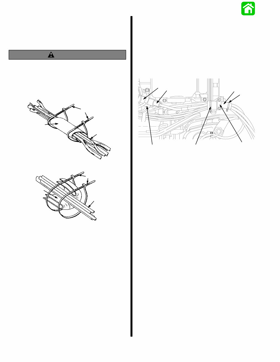
1-6 90-13645--2 495 GENERAL INFORMATION AND SPECIFICATIONS Connecting Engine Wiring Harness and Routing of Engine Battery Cables WARNING Cables passing through cowl must be protected from chafing or being cut, by using the neoprene sheet as described in the following steps. Failure to protect cables as described could result in electrical system failure and/or possible injury to occupants of boat. a b c a b c Models with Power Trim Models without Power Trim a - Wiring Harness b - Neoprene Sheet c - Sta-Straps 1. Plug remote control harness connector into en- gine harness connector, then secure connector in place with retainer as shown. 2. Wrap neoprene sheet around cable bundle and secure each end with a sta-strap. Secure to bracket with retainer. IMPORTANT: On Models without Power Trim, the neoprene sheet must be folded once and then wrapped around cables as shown. 20290 e a b c d f f a - Engine Connector b - Retainer c - Harness Connector d - Harness Retainer e - Neoprene Sheet f - Sta-Strap(s) Models with Power Trim
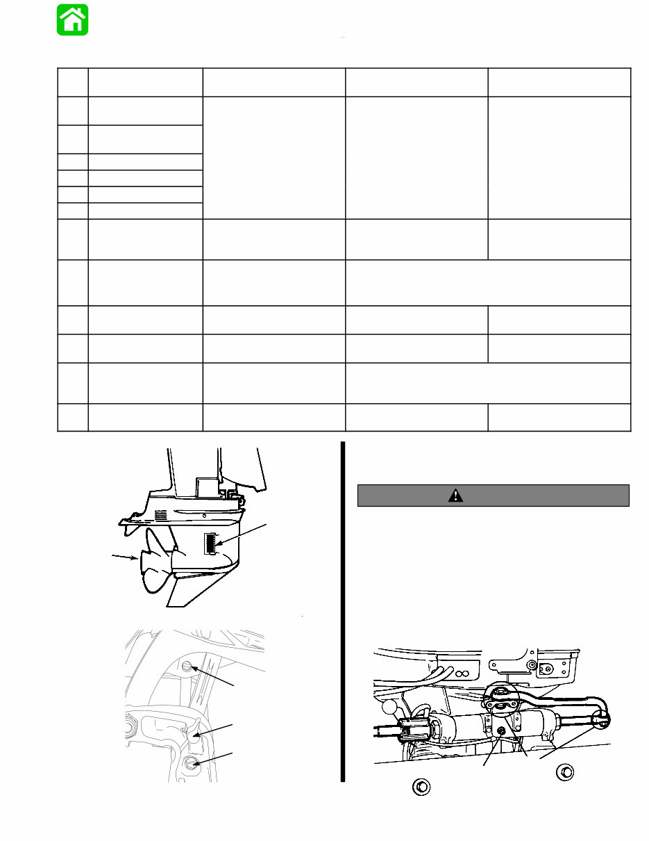
1-7 90-13645--2 495 GENERAL INFORMATION AND SPECIFICATIONS Lubrication Points No. Description Lubricant Used or Maintenance Fresh Water Frequency Salt Water Frequency 1 Ride-Guide Steering Cable 2 Throttle-Shift Linkage Quicksilver C E 60 D E 30 D 3 Upper Shift Shaft 2-4-C w/Teflon Every 60 Days Every 30 Days 4 Tilt Tube w/T eflon 5 Swivel Pin 6 Tilt Lock Lever 7 Propeller Shaft Quicksilver -2-4-C w/Teflon Anti-Corrosion Grease Once in Season Every 60 Days 8 Gear Housing Quicksilver Gear Lube Check and fill after 1st 10 days, then every 30 days Drain and Refill after 1st 25 hours, then after every 100 hours, or once a year before storing. 9 Steering Link Rod Pivot Points SAE 30W Engine Oil Every 60 Days Every 30 Days 10 Power Trim Pump Oil Level Quicksilver Power Trim and Steering Fluid Every 100 hours, or once in season Same as Fresh Water --- Engine Crankshaft Splines to Drive Shaft Splines Quicksilver 2-4-C w/Teflon Once in Season by Dealer 11 Accelerator Pump Stem/Throttle Cam Quicksilver 2-4-C w/Teflon Once in Season Every 60 Days 27868 7 8 20319 6 10 5 Ride-Guide Steering Cable and Pivot Points Lubrication WARNING Core of steering cable (transom end) must be fully retracted into cable housing before lubricating cable. If cable is lubricated while extended, hydraulic lock of cable could occur. With core of Ride-Guide Steering cable (transom end) fully retracted, lubricate transom end of steering cable thru grease fitting and exposed portion of cable end with Quicksilver 2-4-C w/Teflon. Lubricate all piv- ot points with SAE 30W engine oil. 50099 1 4 9
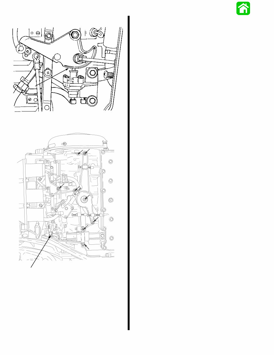
1-8 90-13645--2 495 GENERAL INFORMATION AND SPECIFICATIONS NOTE: 4 CYL. MODELS 22509B 11 11 – Lubrication Points for Accelerator Pump Cam on 4 Cylinder Models Only 18298 2 2 – Lubrication Points are indicated with Arrows Following Complete Submersion Submerged engine treatment is divided into 3 distinct problem areas. The most critical is submersion in salt water; the second is submersion while running. Salt Water Submersion (Special Instructions) Due to the corrosive effect of salt water on internal en- gine components, complete disassembly is neces- sary before any attempt is made to start the engine. Submerged While Running (Special Instructions) When an engine is submerged while running, the possibility of internal engine damage is greatly in- creased. If, after engine is recovered and with spark plugs removed, engine fails to turn over freely when turning flywheel, the possibility of internal damage (bent connecting rod and/or bent crankshaft) exists. If this is the case, the powerhead must be disas- sembled. Submerged Engine (Fresh Water) (Plus Special Instructions) 1. Recover engine as quickly as possible. 2. Remove cowling. 3. Flush outside of engine with fresh water to re- move mud, weeds, etc. DO NOT attempt to start engine if sand has entered powerhead, as power- head will be severely damaged. Disassemble powerhead if necessary to clean components. 4. Remove spark plugs and get as much water as possible out of powerhead. Most water can be eliminated by placing engine in a horizontal posi- tion (with spark plug holes down) and rotating fly- wheel. 5. Pour alcohol into carburetor throat (alcohol will absorb water). Again rotate flywheel. 6. Turn engine over and pour alcohol into spark plug openings and again rotate flywheel. 7. Turn engine over (place spark plug opening down) and pour engine oil into throat of carbure- tors while rotating flywheel to distribute oil throughout crankcase. 8. Again turn engine over and pour approximately one teaspoon of engine oil into each spark plug opening. Again rotate flywheel to distribute oil in cylinders. 9. Remove and clean carburetors and fuel pump assembly.
This is the complete official service repair manual for the Mercury Mariner Outboard 2 Stroke 70 75 80 90 100 115HP, covering production model years 1987 to 1993. It includes complete tear down and rebuild, pictures and part diagrams, torque specs, maintenance, troubleshooting, and more.
This manual contains everything needed to repair, maintain, rebuild, refurbish, or restore the Mercury Mariner Outboard. It covers all diagnostic and repair procedures, with detailed illustrations, diagrams, wiring schematics, specifications, and step-by-step instructions. All pages are printable, making it convenient for use in the garage or workshop. These manuals are suitable for both do-it-yourselfers and experienced mechanics, providing cost-effective maintenance for the outboard.
Contents:
General Information and Specifications
Electrical and Ignition
Ignition System
Battery, Charging System and Starting System
Timing/Synchronizing and Adjusting
Wiring Diagrams
Fuel System and Carburetion
Oil Injection System
Powerhead (3-Cylinder Engines)
Powerhead (4-Cylinder Engines)
Lower Unit
Gear Housing
Mid Section
Shock Absorber
Power Trim
Design I (Side Fill Reservoir)
Design II (Aft Fill Reservoir)
Single Ram
Outboard Motor Installation/Attachments
Engine Attachments/Engine Installation
Tiller Handle and Co-Pilot
Product Details:
File Format: PDF
Total Pages: 391 pages
Compatible: All Versions of Windows & Mac
Delivery: Link will appear on the checkout page after payment is complete
Requirements: Adobe Reader
It's important to buy the right repair manual for your outboard to save costs and gain comprehensive knowledge about its maintenance. The manual is printable, and a preview of some pages is available for reference.
Recently Viewed
5,521,897Happy Clients
2,594,462eManuals
1,120,453Trusted Sellers
15Years in Business
Price:
Actual Price:
1987-1993 MERCURY MARINER OUTBOARD 2 Stroke 70 75 80 90 100 115 HP Motors Service Repair Manual ( Preview, Complete FSM Conta