

1987-1993 Mercury Mariner 70/75/80/90/100/115 HP Outboards Service & Repair Manual
What's Included?
Fast Download Speeds
Online & Offline Access
Access PDF Contents & Bookmarks
Full Search Facility
Print one or all pages of your manual
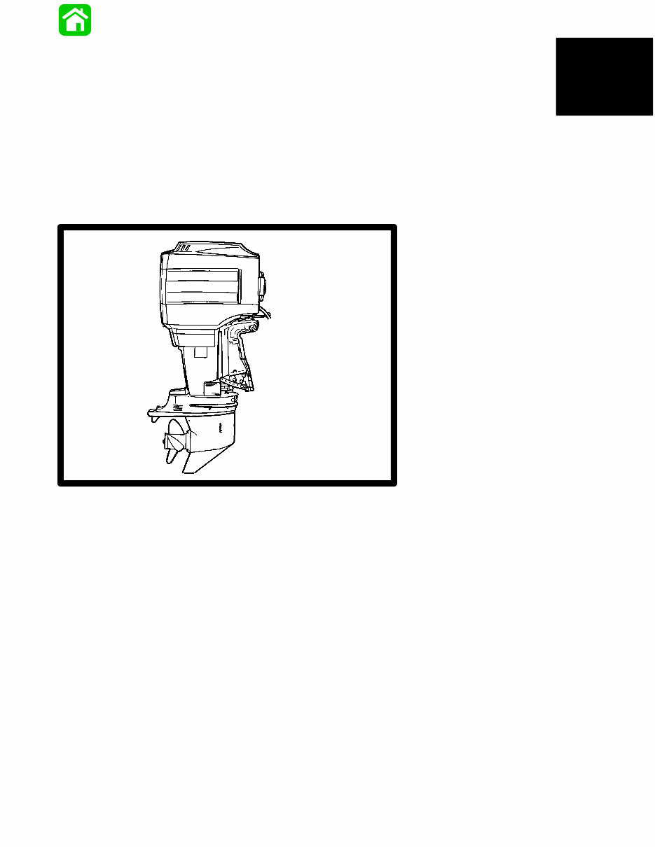
(3 Cylinder)
UNITED STATES S/N 0A996142 thru 0D283221
BELGIUM S/N 09502135 thru 09793576
CANADA S/N 0A722297 and Above
BELGIUM
CANADA
S/N 0B209468 thru 0D283221
S/N 09523034 thru 09793576
S/N 0A731673 and Above
MODELS
70 • 75 • 80 • 90 • 100 • 115
SERVICE
MANUAL
1987–1993 70 • 75 • 75 Marathon •
75XD • 75 Seapro • 80 • 90
1988–1993 100 • 115 (4 Cylinder)
with Serial Numbers
with Serial Numbers
UNITED STATES
Printed in U.S.A.
1995, Brunswick Corporation
90-13645--2 1095
Notice
Throughout this publication, “Dangers”, “Warnings”
and “Cautions” (outlined in a border and accompa-
nied by the International HAZARD Symbol ) are
used to alert the mechanic to special instructions con-
cerning a particular service or operation that may be
hazardous if performed incorrectly or carelessly.
OBSERVE THEM CAREFULLY!
These “Safety Alerts” alone cannot eliminate the
hazards that they signal. Strict compliance to these
special instructions when performing the service, plus
“common sense” operation, are major accident
prevention measures.
DANGER
DANGER — Immediate hazards which WILL result
in severe personal injury or death.
WARNING
WARNING - Hazards or unsafe practices which
COULD result in severe personal injury or death.
CAUTION — Hazards or unsafe practices which
could result in minor personal injury or product or
property damage.
CAUTION
Notice to Users of This Manual
This service manual has been written and published
by the service department of Mercury Marine to aid
our dealers’ mechanics and company service person-
nel when servicing the products described herein.
It is assumed that these personnel are familiar with
the servicing procedures of these products, or like or
similar products manufactured and marketed by Mer-
cury Marine, that they have been trained in the recom-
mended servicing procedures of these products
which includes the use of mechanic’s common hand
tools and the special Mercury Marine or recom-
mended tools from other suppliers.
We could not possibly know of and advise the service
trade of all conceivable procedures by which a ser-
vice might be performed and of the possible hazards
and/or results of each method. We have not under-
taken any such wide evaluation. Therefore, anyone
who uses a service procedure and/or tool, which is
not recommended by the manufacturer, first must
completely satisfy himself that neither his nor the
product’s safety will be endangered by the service
procedure selected.
All information, illustrations and specifications con-
tained in this manual are based on the latest product
information available at the time of publication. As re-
quired, revisions to this manual will be sent to all deal-
ers contracted by us to sell and/or service these prod-
ucts.
It should be kept in mind, while working on the
product, that the electrical system and ignition system
is capable of violent and damaging short circuits or
severe electrical shocks. When performing any work
where electrical terminals could possibly be
grounded or touched by the mechanic, the battery
cables should be disconnected at the battery.
Any time the intake or exhaust openings are exposed
during service they should be covered to protect
against accidental entrance of foreign material which
could enter the cylinders and cause extensive inter-
nal damage when the engine is started.
It is important to note that, during any maintenance
procedure, replacement fasteners must have the
same measurements and strength as those re-
moved, whether metric or customary. Numbers on the
heads of the metric bolts and on surfaces of metric
nuts indicate their strength. Customary bolts use ra-
dial lines for this purpose, while most customary nuts
do not have strength markings. Mismatched or incor-
rect fasteners can result in damage or malfunction, or
possible personal injury. Therefore, fasteners re-
moved should be saved for re-use in the same loca-
tions whenever possible. Where the fasteners are not
satisfactory for re-use care should be taken to select
a replacement that matches the original.

Cleanliness and Care of
Outboard Motor
A marine power product is a combination of many ma-
chined, honed, polished and lapped surfaces with tol-
erances that are measured in the ten thousands of an
inch. When any product component is serviced, care
and cleanliness are important. Throughout this
manual, it should be understood that proper cleaning,
and protection of machined surfaces and friction
areas is a part of the repair procedure. This is consid-
ered standard shop practice even if not specifically
stated.
Whenever components are removed for service, they
should be retained in order. At the time of installation,
they should be installed in the same locations and
with the same mating surfaces as when removed.
Before raising or removing an outboard engine from a
boat, the following precautions should be adhered to:
1. Check that flywheel is secured to end of
crankshaft with a locknut and lifting eye is
threaded into flywheel a minimum of 5 turns.
2. Connect a hoist of suitable strength to the lifting
eye.
In addition, personnel should not work on or under an
engine which is suspended. Engines should be at-
tached to work stands, or lowered to ground as soon
as possible.
We reserve the right to make changes to this manual
without prior notification.
Refer to dealer service bulletins for other pertinent in-
formation concerning the products described in this
manual.
Service Manual Outline
1 - General Information and Specifications
2 - Electrical and Ignition
A - Ignition System
B - Battery, Charging System and
Starting System
C - Timing/Synchronizing and Adjusting
D - Wiring Diagrams
3 A - Fuel System and Carburetion
B - Oil Injection System
4 A - Powerhead (3-Cylinder Engines)
B - Powerhead (4-Cylinder Engines)
5 - Lower Unit
A - Gear Housing
B - Mid Section
C - Shock Absorber
6 - Power Trim
A - Design I (Side Fill Reservoir)
B - Design II (Aft Fill Reservoir)
C - Single Ram
7 - Outboard Motor Installation/Attachments
A - Engine Attachments/Engine Installation
B - Tiller Handle and Co-Pilot
GENERAL INFORMATION
AND SPECIFICATIONS
1

90-13645-2 495
Table Of Contents
Page Page
General Specification 1-1 . . . . . . . . . . . . . . . . . . . . . .
Cowl Removal 1-3 . . . . . . . . . . . . . . . . . . . . . . . . . . . .
Filling Oil Injection System 1-3 . . . . . . . . . . . . . . . . . .
Power Trim General Information 1-4 . . . . . . . . . . . . .
Trim “In” Angle Adjustment 1-4 . . . . . . . . . . . . . . . . .
Models with Power Trim 1-4 . . . . . . . . . . . . . . . .
Checking Trim System Fluid Level 1-5 . . . . . . . . . . .
Tilt Angle Adjustment 1-5 . . . . . . . . . . . . . . . . . . . . . .
Models without Power Trim 1-5 . . . . . . . . . . . . . .
Connecting Engine Wiring Harness and
Routing of Engine Battery Cables 1-6 . . . . . . . .
Ride-Guide Steering Cable and
Pivot Points Lubrication 1-7 . . . . . . . . . . . . . . . . .
Following Complete Submersion 1-8 . . . . . . . . . . . .
Salt Water Submersion
(Special Instructions) 1-8 . . . . . . . . . . . . . . . .
Submerged While Running
(Special Instructions) 1-8 . . . . . . . . . . . . . . . .
Submerged Engine (Fresh Water)
(Plus Special Instructions) 1-8 . . . . . . . . . . .
Out-of-Season Outboard Storage 1-9 . . . . . . . . . . .
How Weather Affects Engine Performance 1-10 . .
Conditions Affecting Operation 1-11 . . . . . . . . . . . . .
Detonation: Causes and Prevention 1-12 . . . . . . . .
Compression Check 1-12 . . . . . . . . . . . . . . . . . . . . . .

1-1 90-13645--2 1095 GENERAL INFORMATION AND SPECIFICATIONS
General Specification
NOTE: Other specification (torques, etc.) are listed in
the respective sections.
Model 70 Model 75 Model 80 Model 90
Horsepower 70 (52.2 kw) 75 (55.9 kw) 80 (59.6 kw) 90 (67.1 kw)
Idle RPM (in forward gear) 650 - 700
Full Throttle RPM Range 4750 - 5250 5000 - 5500
Piston Replacement 71.12 (1165.7cc)
Cylinder Bore 3.375 (85.7mm)
Stroke 2.65 (67.3mm)
Engine Type 3 Cylinder, 2 Cycle
Ignition Type C.D. Breakerless
Recommended Spark Plug
NGK-BUHW-2 or AC-V40 FFK or
Champion L78V
Inductor Plugs: NGK-BUZHW-2 or
Champion QL78V
Cylinder Firing Order 1-3-2
Recommended Power Trim Fluid
Quicksilver Power Trim & Steering Fluid or Automotive Transmission
Fluid (ATF) Type F, FA or Dexron II
Recommended Gasoline
Regular Leaded, Premium, Low-Lead and Lead-Free automotive gaso-
lines with a minimum pump posted octane rating of 86
Recommended Oil Quicksilver TC-WII or TC-W3 2-Cycle Outboard Oil
Engine Weight ELO
ELOPT
260 lbs.
280 lbs.
Fuel Tank Capacity
6.6 U.S. Gallons
(5 Imp. Gals.; 25 Liters)
Gear Housing Lubricant Capacity 22.5 fl. oz. (665.3ml)
Gasoline/Oil Ratio at Idle 80:1
Gasoline/Oil Ratio at W.O.T. 50:1
Gear Ratio 2.3:1
Oil Injection Tank Capacity
Tank Capacity 1 gal. (3.78 liter)
Maximum operation per tank
full of oil at W.O.T.
6 hours
Oil remaining when warning
buzzer sounds
1 qt. (.95 liter)
Operating time remaining at
wide open throttle when warn-
ing buzzer sounds
1 Hour

1-2 90-13645--2 1095 GENERAL INFORMATION AND SPECIFICATIONS
General Specification
(continued)
NOTE: Other specification (torques, etc.) are listed in
the respective sections.
Model 100 Model 115
Horsepower 100 (74.6 kw) 115 (85.8 kw)
Idle RPM (in forward gear) 650 - 700
Full Throttle RPM Range 4750 - 5250
Piston Replacement 105 (1720.9cc)
Cylinder Bore 3.375 (85.7mm)
Stroke 2.930 (74.4mm)
Engine Type 4 Cylinder, 2 Cycle
Ignition Type C.D. Breakerless
Recommended Spark Plug
NGK-BPH8H-N-10* Gap - 0.040 in. (1.0mm)
Inductor Plug NGK BPZ 8H-N-10* Gap - 0.040 in. (1.0mm)
NGK-BUHW
Cylinder Firing Order 1-3-2-4
Recommended Power Trim Fluid
Quicksilver Power Trim & Steering Fluid or Automotive Transmission
Fluid (ATF) Type F, FA or Dexron II
Recommended Gasoline
Regular Leaded, Premium, Low-Lead and Lead-Free automotive gaso-
lines with a minimum pump posted octane rating of 86
Recommended Oil Quicksilver 2-Cycle Outboard Oil
Engine Weight ELO
ELOPT
340 lbs.
360 lbs.
Fuel Tank Capacity
6.6 U.S. Gallons
(5 Imp. Gals.; 25 Liters)
Gear Housing Lubricant Capacity 22.5 fl. oz. (665.2ml)
Gasoline/Oil Ratio at Idle 80:1
Gasoline/Oil Ratio at W.O.T. 50:1
Gear Ratio 2.07:1
Oil Injection Tank Capacity
Tank Capacity 1.4 gal. (5.3 liters)
Maximum operation per tank
full of oil at W.O.T.
5 hours
Oil remaining when warning
buzzer sounds
1 qt. (.95 liter)
Operating time remaining at
wide open throttle when warn-
ing buzzer sounds
50 min. approx.
*Improves running quality between 1800 – 2000 RPM.
90-13645--2 495 1-3 GENERAL INFORMATION AND SPECIFICATIONS
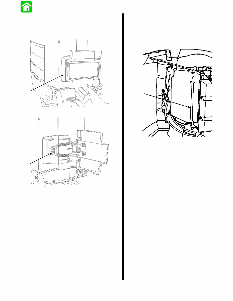
Cowl Removal
Pull outward on starboard side of front shield (a).
Remove spring (b) from latch and open cowls.
18291
a
18292
b
Filling Oil Injection System
Open starboard cowl (refer to cowl removal on this
page). Some earlier outboards will have a cowl brack-
et to hold cowl open as shown.
Fill tank with recommended oil.
a
a - Oil Tank Tube
1-4 90-13645--2 495 GENERAL INFORMATION AND SPECIFICATIONS
Power Trim System
GENERAL INFORMATION
The power trim system is filled at the manufacturer
and is ready for use.
Trim outboard through entire trailering range several
times to remove any air from the system.
The trim system is pressurized and is not externally
vented. The outboard can be raised or lowered manu-
ally by loosening the manual release valve four turns.
The trim “out” angle of this outboard is not adjustable.
The trim system has an internal valve which will
automatically stop the outward trim travel at 20_ when
engine RPM is approximately 2000 RPM or higher;
outboard also has to be in water and in gear.
The outboard can be operated beyond the 20_ trim
limit for operating outboard in shallow water if engine
RPM is kept below approximately 2000 RPM.
a
b
23321
a - Fill Screw (System is Pressurized, DO NOT Open Unless
Outboard is Tilted to Full Up Position)
b - Manual Release Valve
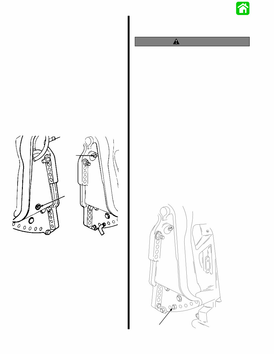
Trim “In” Angle Adjustment
MODELS WITH POWER TRIM
WARNING
Operating some boats with outboard trimmed to the
full “in” trim angle [not using trim adjustment bolt
(a)] at planing speed will cause undesirable and/or
unsafe steering conditions. Each boat MUST BE
water tested for handling characteristics after
outboard installation and after any trim adjust-
ments.
IMPORTANT: Some boat/motor combinations,
that do not use the trim adjustment bolt (a) and are
trimmed to the full “in” trim angle, will not experi-
ence any undesirable and/or unsafe steering
conditions during planing speed. Thus, not using
trim adjustment bolt may be desired. However,
some boats with outboard trimmed to the full “in”
trim angle at planing speeds will cause undesir-
able and/or unsafe steering conditions. If these
steering conditions are experienced, under no
circumstances should the outboard be operated
without the trim adjustment bolt and without the
bolt adjusted in the proper holes to prevent un-
safe handling characteristics.
Water test the boat not using the trim adjustment bolt.
If undesirable and/or unsafe steering conditions are
experienced (boat runs with nose down), install trim
adjustment bolt in proper hole to prevent unsafe han-
dling characteristics.
22744
a
90-13645--2 495 1-5 GENERAL INFORMATION AND SPECIFICATIONS
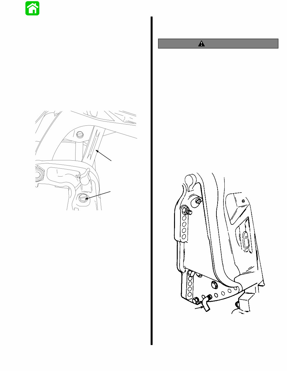
Checking Trim System Fluid Level
IMPORTANT: This trim system is pressurized.
Remove fill screw (b) when outboard is trimmed
to the full “up” position. Retighten fill screw
securely.
1. Trim outboard to full “up” position. Engage tilt lock
lever. Trim system fluid can only be checked when
outboard is in this position.
2. Remove fill screw and check fluid level. Fluid level
should be visible in fill tube.
3. If necessary, add Quicksilver Power Trim and
Steering Fluid; or Automatic Transmission Fluid
(ATF) Type F, FA or Dextron II.
20319
a
b
a - Tilt Lock Lever
b - Fill Screw
Tilt Angle Adjustment
MODELS WITHOUT POWER TRIM
WARNING
Operating some boats at minimum trim “In” at
planing speeds will cause undesirable and/or
unsafe steering conditions. Each boat should be
tested for handling characteristics after any
adjustment is made to the tilt angle.
DO NOT OPERATE motor with tilt lock pin removed.
Adjust tilt angle of motor on transom with tilt lock pin
so that anti-ventilation plate is about parallel and even
with bottom of boat. Speed sometimes may be im-
proved by tilting motor out one tilt pin hole to raise bow
and reduce wetted surface. If motor is tilted in, boat
will ride bow down, wetting more of the bottom and re-
ducing speed, which generally will improve operation
in rough water. Under ideal conditions, efficiency is
best with lower unit operating in level position. Opera-
tion with excessive tilt angle will reduce performance
noticeably and may induce ventilation. It is preferable
to level boat by proper loading rather than by extreme
adjustment of tilt angle.
22744
a
a - Tilt Lock Pin
You're Reading a Preview
What's Included?
Fast Download Speeds
Online & Offline Access
Access PDF Contents & Bookmarks
Full Search Facility
Print one or all pages of your manual
$30.99
Viewed 90 Times Today


Secure transaction
What's Included?
Fast Download Speeds
Online & Offline Access
Access PDF Contents & Bookmarks
Full Search Facility
Print one or all pages of your manual
$30.99
- This service repair manual is designed for the Mercury Mariner Outboard 70 75 80 90 100 115 HP models, covering 3/4 cylinder models from 1987 to 1993.
- It includes detailed maintenance and repair procedures, making it suitable for professional mechanics and DIY enthusiasts.
- The manual covers general information, specifications, electrical and ignition systems, fuel system, powerhead, lower unit, power trim, outboard motor installation, and more.
- It features step-by-step instructions, highly detailed exploded pictures, and diagrams to ensure correct and efficient completion of repair procedures.
- With instant access, there are no shipping costs or waiting for physical delivery. The manual is compatible with all versions of Windows and Mac, and it is available in English language.
- Upon payment completion via a secure processor, the manual can be received instantly and all pages are printable for convenience.
File Format:
.PDF (Portable Document Format)


