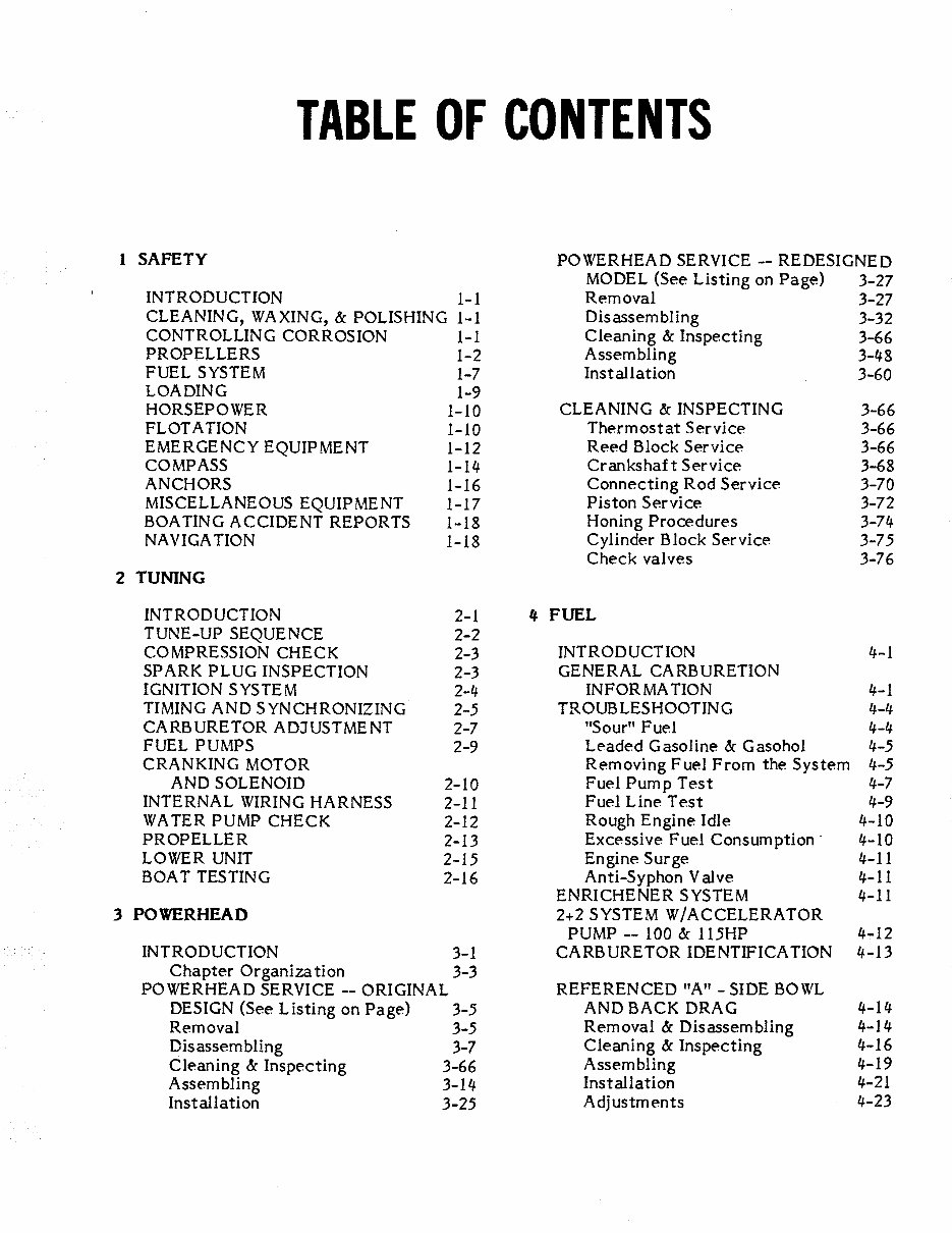
TABLE OF CONTENTS 1 SAFETY INTRODUCTION 1-1 CLEANING, WAXING, & POLISHING 1-1 CONTROLLING CORROSION 1-1 PROPELLERS 1-2 FUEL SYSTEM 1-7 LOADING 1-9 HORSEPOWER 1-10 FLOTATION 1-10 EMERGENCY EQUIPMENT 1 皿 12 COMPASS 1-14 ANCHORS 1-16 MISCELLANEOUS EQUIPMENT 1-17 BOATING ACCIDENT REPORTS 1-18 NAVIGATION 1-18 2 TUNING INTRODUCTION 2-1 TUNE-UP SEQUENCE 2-2 COMPRESSION CHECK 2-3 SPARK PLUG INSPECTION 2-3 IGNITION SYSTEM 2,每 TIMING ANDS YNCHRONIZING 2-5 CARBURETOR ADJUSTMENT 2-7 FUEL PUMPS 2-9 CRANKING MOTOR AND SOLENOID 2-1 O INTERNAL WIRING HARNESS 2-11 WATER PUMP CHECK 2-12 PROPELLER 2-13 LOWER UNIT 2-15 BOAT TESTING 2-16 3 POWERHEAD INTRODUCTION 3-1 Chapter Organization 3-3 POWERHEAD SERVICE -- ORIGINAL DESIGN (See Listing on Page) 3-5 Removal 3-5 Disassembling 3-7 Cleaning & Inspecting 3-66 Assembling 3-14 Installation 3-25 POWERHEAD SERVICE -- REDESIGNED MODEL (See Listing 。n Page) 3-27 Removal 3-27 Disassembling 3-32 Cleaning & Inspecting 3-66 Assembling 3-48 Installation 3-60 CLEANING & INSPECTING 3-66 Therm 。stat Service 3-66 Reed Block Service 3-66 Crankshaft Service 3-68 c。nnecting R 。d Service 3-70 Piston Service 3-72 Honing Procedures 3-7电 Cylinder Block Service 3-75 Check valves 3-76 电 FUEL INTRODUCTION GENERAL CARBURETION INFORMATION TROUBLESHOOTING ”Sour" Fuel Leaded Gas。line & Gasoh。l Rem 。ving Fuel From the System Fuel Pump Test Fuel Line Test R。ugh Engine Idle Excessive Fuel Consumption Engine Surge Anti-Syph。n Valve ENRICHENER SYSTEM 2+2 SYSTEM W/ACCELERATOR PUMP -- 100 & 115HP CARBURETOR IDENTIFICATION REFERENCED "A”- SIDE BOWL AND BACK DRAG Removal & Disassembling Cleanin~ & Inspecting Assembling Installation Adjustments 每- 1 4-1 4-4 每·电 年,5 4-5 4-7 4-9 4-10 4-10 4-11 4-11 4-11 龟, 12 年- 13 每- 1 乌 龟- 1 每 每- 16 件- 19 4-21 龟-23
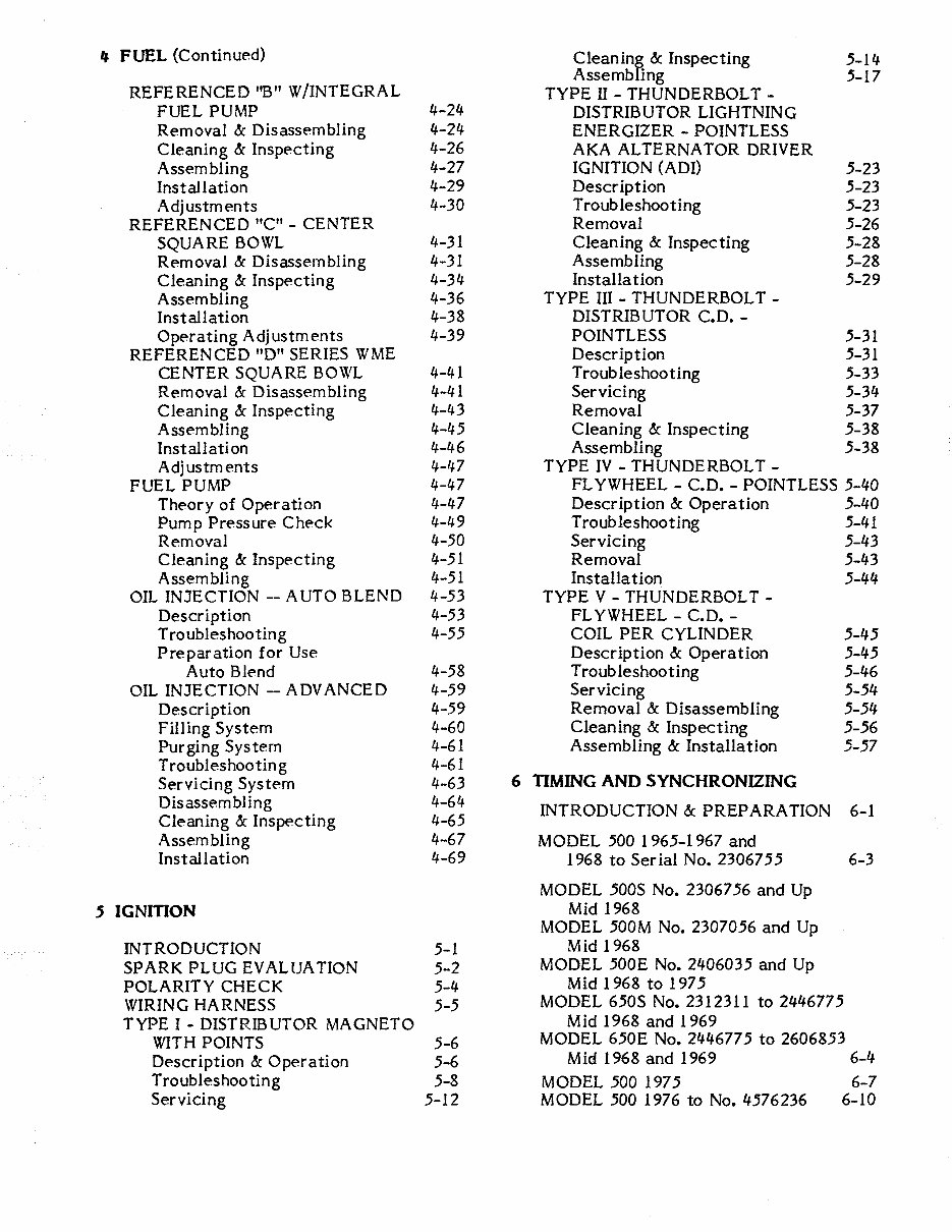
电 FUEL (Continued) Clean in俨 Inspecting .5-1 每 Assemb ng .5-17 REFERENCED ” B" W/INTEGRAL TYPE II - THUNDERBOLT - FUEL PUMP 电-2龟 DISTRIBUTOR LIGHTNING Rem 。val & Disassembling 电-2龟 ENERGIZER - POINTLESS Cleaning & Inspecting 每- 26 AKA ALTERNATOR DRIVER Assembling 1 斗-27 IGNITION (ADI) .5-23 Installation 年,29 Description .5-23 Adjustments 电-30 Troubleshooting .5-23 REFERENCED "C”- CENTER Removal 5-26 SQUARE BOWL 4-31 Cleaning & Inspecting .5-28 Rem 。val & Disassembling 年-31 Assembling .5-28 Cleaning & Inspecting 龟-3 每 Installation .5-29 Assembling 鸟-36 TYPE III - THUNDERBOLT - Installation 4-38 DISTRIBUTOR C.D. - Operating Adjustments 电-39 POINTLESS 5-31 REFERENCED "D" SERIES W ME Description .5-31 CENTER SQUARE BOWL 件-电 1 Trot』b leshooting .5-33 Rem 。val & Disassembling 也-每 1 Servicing .5-3句 Cleaning & Inspecting 电-电3 Removal .5-37 Assembling 电-4.5 Cleaning & Inspecting .5-38 Installation 年-46 Assembling .5-38 Adjustments 1 斗-47 TYPE IV - THUNDERBOLT - FUEL PUMP 饵-饵 7 FLYWHEEL - C.D. - POINTLESS .5-句。 Theory 。f Operation 民-47 Description & Operation .5-斗。 Pump Pressure Check 4-49 Tr。ublesho。ting .5-每 i Removal 每-50 Servicing .5-句3 Cleaning & Inspecting 4-51 Removal .5-电3 Assembling 4-51 Installation .5-句句 OIL INJECTION -- AUTO BLEND 龟 -53 TYPE V - THUNDERBOLT - Description 件-53 FLYWHEEL - C.D. - Tr。 ublesh。oting 电-55 COIL PER CYLINDER .5-每5 Preparation for Use Description & Operation .5-与5 Auto Blend 年-58 Troubleshooting .5-句6 OIL INJECTION --ADVANCED 4-59 Servicing 5白5句 Descripti。n 4-59 Removal & Disassembling .5-.5每 Filling System 4-60 Cleaning & Inspecting .5-.56 Purging System 年-61 Assembling & Installation 5-57 Troubleshooting 每-61 Servicing System 4-63 6 TIMING AND SYNCHRONIZING Disassembling 鸟-6 鸟 INTRODUCTION & PREPARATION 6-1 Cleaning & Inspecting 4-65 Assembling 4-67 MODEL .500 1 965-1 967 and Installation 4-69 1968 t。 Serial No. 23067.55 6-3 MODEL 500S N。. 23067 56 and Up 5 IGNIηON Mid 1968 MODEL .500M N。. 23070.56 and Up INTRODUCTION 5-1 Mid 1968 SPARK PLUG EVALUATION 5-2 MODEL .500E N。. 2句0603.5 and Up POLARITY CHECK 5-龟 Mid 1968 t。 197.5 WIRING HARNESS 5 ” 5 MODEL 6.50S No. 2312311 to 24每677.5 TYPE I - DISTRIBUTOR MAGNETO Mid 1968 and 1969 WITH POINTS 5-6 MODEL 650E No. 2每每677.5 to 2606853 Description & Operation 5-6 Mid 1968 and 1969 6-每 Troubleshooting 5-8 MODEL 500 197 5 6-7 Servicing 5-12 MODEL 500 1976 to N。.句576236 6喃 10
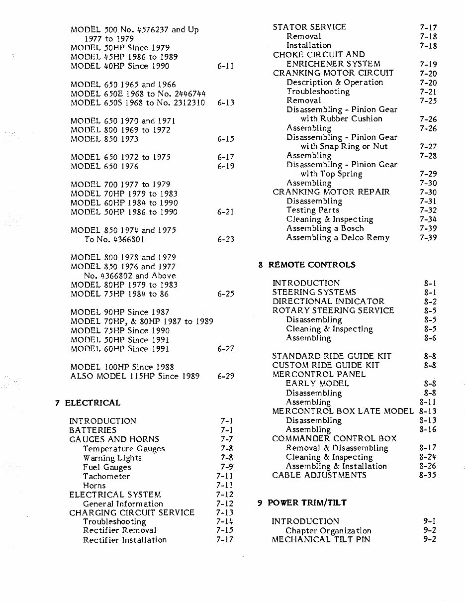
MODEL 500 No. 4576237 and Up STA TOR SERVICE 7-17 1977 to 1979 Removal 7-18 MODEL 50HP Since 1979 Installation 7-18 MODEL 45HP 1986 to 1989 CHOKE CIRCUIT AND MODEL 40HP Since 1990 6-11 ENRICHENER SYSTEM 7-19 CRANKING MOTOR CIRCUIT 7-20 MODEL 650 1965 and 1966 Description & Oper ati。n 7-20 MODEL 650E 1968 to No. 2446744 Tr。 ublesho。ting 7-21 MODEL 650S 1968 t。 N。. 2312310 6-13 Removal 7-25 Disassembling - Pinion Gear MODEL 650 1970 and 1971 with Rubber C ushi 。n 7-26 MODEL 800 1969 to 1972 Assembling 7-26 MODEL 850 1973 6-15 Disassembling - Pinion Gear with Snap Ring or Nut 7-27 MODEL 650 1972 t。 1975 6-17 Assembling 7-28 MODEL 650 1976 6-19 Disassembling - Pinion Gear with Top Spring 7-29 MODEL 700 1977 t,。 1979 Assembling 7-30 MODEL 70HP 1979 to 1983 CRANKING MOTOR REPAIR 7-30 MODEL 60HP 198 每 t。 1990 Disassembling 7-31 MODEL 50HP 1986 to 1990 6-21 Testing Parts 7-32 Cleaning & Inspecting 7-34 MODEL 850 197斗 and 1975 Assembling a Bosch 7-39 ToN。.斗366801 6-23 Assembling a Delco Remy 7-39 MODEL 800 1978 and 1979 MODEL 850 1976 and 1977 8 REMOTE CONTROLS No. 4366802 and Above MODEL 80HP 1979 t。 1983 INTRODUCTION 8-1 MODEL 75HP 1984 to 86 6-25 STEERING SYSTEMS 8-1 DIRECTIONAL IN DI CA TOR 8-2 MODEL 90HP Since 1987 ROTARY STEERING SERVICE 8-5 MODEL 70HP, & 80HP 1987 to 1989 Disassembling 8-5 MODEL 75HP Since 1990 Cleaning & Inspecting 8-5 MODEL 50HP Since 1991 Assembling 8-6 MODEL 60HP Since 1991 6-27 STANDARD RIDE GUIDE KIT 8-8 MODEL lOOHP Since 1988 CUSTOM RIDE GUIDE KIT 8-8 ALSO MODEL 115HP Since 1989 6-29 MERCONTROL PANEL EARLY MODEL 8-8 Disassembling 8-8 7 ELECTRICAL Assembling 8-11 MERCONTROL BOX LATE MODEL 8-13 INTRODUCTION 7-1 Disassembling 8-13 BATTERIES 7-1 Assembling 8-16 GAUGES AND HORNS 7-7 COMMANDER CONTROL BOX Temperature Gauges 7-8 Rem 。val & Disassembling 8-17 Warning Lights 7-8 Cleaning & Inspecting 8-24 Fuel Gauges 7-9 Assembling & Installation 8-26 Tachometer 7-11 CABLE ADJUSTMENTS 8-35 Horns 7-11 ELECTRICAL SYSTEM 7-12 General Information 7-12 9 POWER TRIM/TILT CHARGING CIRCUIT SERVICE 7-13 Troubleshooting 7-1 每 INTRODUCTION 9-1 Rectifier Rem 。val 7-15 Chapter Organization 9-2 Rectifier Installation 7-17 MECHANICAL TILT PIN 9-2
9 POWER TRIM/TILT (Continued) Disassembli~~ Bearing rr ier 10-16 SYSTEM "A”, MODELS WITH TWO Pr。peller Shaft 10-17 TRIM/TILT CYLINDERS 9-3 Drive shaft 10-17 Description&: Operation 9-3 Special Instructions 9-5 Assemblint Bleeding 9-6 Lower riveshaft Bearing 10-22 Trouble sh。oting 9-8 Shift Shaft 10-22 Trim Switch Service 9-8 Bearing Carrier 10-23 Service System ” A" 9-12 Forward Gear&: Bearing 10-2句 Hydraulic Pump Service 9-1 句 F。rward Bearing Race 10-25 Electric Motor Service 9-17 Driveshaft 10-26 Shimming &: Backlash SYSTEM "B”- MODELS WITH TWO Pinion Gear Depth 10-28 TRIM CYLINDERS Forward Gear Backlash 10-29 AND ONE TILT CYLINDER 9-21 Assembling &: Installation Description &: Operation 9-21 Bearing Carrier 10-32 Bleeding 9-22 Reverse Gear Backlash ·I0-33 Flushing 9-23 Tr。ublesho。ting 9-2每 SERVICING CAM由SHIFT TYPE II Removal &: Disassembling 9-31 UNITS MATCHED WITH LA TE Manual Release Valve 9-3每 3- and 句-CYLINDER POWERHEADS Oil Reserv。ir c。ver 9-35 SINCE ABOUT 1980 10-3句 Trim Cylinders 9-35 Removal and Disassembling Tilt Cylinder 9-36 Bearing Carrier 10-35 Motor &: Pump 9-36 Propeller Shaft 10-36 Cleaning &: Inspecting 9-37 Shift Shaft 10-37 Assembling &: Installation 9-38 Pinion Gear 10-38 Pump &: Motor 9-42 Driveshaft 10-38 Tilt Cylinder 9-每5 F。rward Gear 10-39 Trim Cylinders 9-句 8 Pinion Gear Bearing Race 10-40 Reservoir Cover 9由每9 Forward Bearing Race 10 -句。 Manual Release Valve 9-每9 Driveshaft Bearing 10,每O System Installati。n 9-50 Assembling and Installation Driveshaf t Bearing 10 -电l 10 LOWER UNIT Pinion Gear Bearing Race 10 -每每 Forward Gear Bearing Race 10-44 DESCRIPTION 10-1 Shift Shaft 10-45 CHAPTER COVERAGE 10-1 Forward Gear 10-每5 TROUBLESHOOTING 10 -句 Driveshaft 10-句6 REMOVAL -- ALL UNITS 10-5 Pinion Gear 10 -每6 Pr。peller Shaft 10-47 Propeller Removal 10-7 Bearing Carrier 10 -每8 WATER PUMP SERVICE Pinion Gear Depth 10-49 Removal and Disassembling F。rward Gear Backlash 10-50 High Pressure Type Pump 10-8 WATER PUMP ASSEMBLING AND High Volume Type Pump 10-9 INSTALLATION High Pressure Type Pump 10-52 SERVICING CAM-SHIFT TYPE I Shimming (Certain Units) 10-52 UNITS MATCHED WITH EARLY High Volume Type Pump 10-56 3-CYLINDER POWERHEADS CLEANING AND INSPECTING TO ABOUT 1979 10-11 ALL UNITS 10-57 Removal Bearing Carrier and LOWER UNIT INSTALLATION 10-60 Propeller Shaft 10-12 Filling Lower Unit 10-60 Driveshaft &: Bearing 10-13 Exhaust Tube Installation 10-61 For ward Gear &: Bearing 10-15 Propeller Installation 10-64
11 HAND REWIND STARTER PROPELLER SERVICE 12-13 POWER TRIM/TILT 12-15 INTRODUCTION INSIDE THE BOAT 12-16 TYPE ”A ”( See Introduction) 11-2 LOWER UNIT 12-16 Rem。val and Disassembling 11-2 WINTER STORAGE 12-18 Cleaning and Inspecting 11 -每 Units With Oil Injection 12-19 Assembling and Installation 11-6 Battery Storage 12-20 Type 吧”(See Introduction) APPENDIX Rem。val and Disassembling 11-13 Cleaning and Inspecting 11-16 METRIC CONVERSION CHART A-1 Assembling and Installation 11-17 ENGINE SPECIFICATIONS AND TUNE-UP ADJ. A-2 thru A-12 12 MAINTENANCE REED STOP OPENING A-13 INTRODUCTION 12-1 CARBURETOR JET SIZE/ ELEVATION CHART A-1 年 OUTBOARD SERIAL NUMBERS 12-2 LOWER UNIT BACKLASH TABLE A“ 16 LUBRICATION - COMPLETE UNIT 12-2 LOWER UNIT OIL CAPACITY PRE-SEASON PREPARATION 12-3 AND GEAR CHART A-17 Units With Oil Injection 12 -句 PISTON & CYLINDER All Units 12-5 SPECIFICATIONS A-18 FIBERGLASS HULLS 12-10 WIRE IDENTIFICATION DWGS. BELOW WATERLINE SERVICE 12-10 Ignition Systems A-19 thru A-39 SUBMERGED ENGINE SERVICE 12-11 Power Trim/TH t A -斗。 Salt Water Submersion 12-11 Remote c。ntrols A -斗3 Fresh Water Submersion 12-12 Console Wiring A-47
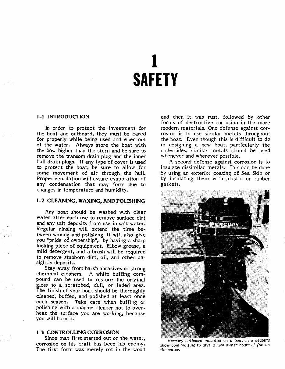
SAFETY 1-1 INTRODUCTION In order to protect the investment for the boat and 。utboard, they must be cared for properly while being used and when out of the water. Always store the boat with the bow higher than the stern and be sure to remove the transom drain plug and the inner hull drain plugs. If any type of c。ver is used to protect the boat, be sure to allow for some m。vement of air through the hull. Proper ventilation will assure evaporation of any condensation that may form due to changes in temperature and humidity. 1-2 CLEAN剧G, WAXING, AND POLISHING Any boat shot』Id be washed with clear water after each use to rem。ve surface dirt and any salt dep。sits fr。m use in salt water. Regular rinsing will extend the time be- tween waxing and polishing. It will also give y。u ”pride of 。wnership”, by having a sharp looking piece of equipment. Elbow grease, a mild detergent, and a brush will be required t。 rem。ve stubb。rn dirt,。 il, and other un- sightly deposits. Stay away from harsh abrasives 。r strong chemical cleaners. A white buffing com- pound can be used to restore the original gl。ss to a scratched, dull,。r faded area. The finish 。f your boat sh。uld be thoroughly cleaned, buffed, and p。lished at least once each seas。n. Take care when buffing or polishing with a marine cleaner not to over- heat the surface y。u are w。rking, because you will burn it. 1-3 .~ONTROLLING CORROSION Since man first started 。ut on the water, corrosi。n on his craft has been his enemy. The first form was merely rot in the wood and then it was rust, followed by other forms of destructive corrosion in the m。re modern materials. One defense against c。r- rosion is to use similar metals throughout the boat. Even though this is difficult to d。 in designing a new boat, particularly the undersides, similar metals should be used whenever and wherever possible. A second defense against corr。sion is to insulate dissimilar metals. This can be d。ne by using an exterior coating of Sea Skin or by insulating them with plastic or rubber gaskets. Mercury outboαrd mounted on α boat in a deαler’s showroom waiting to give α new owner hours of fun on the wαter.
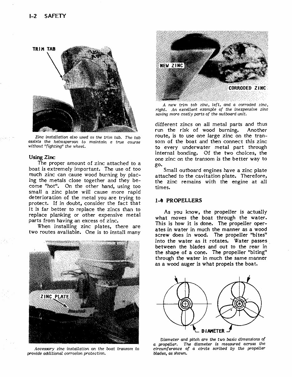
1-2 SAFETY Zinc instαllαti on αlso used αs the trim tab. The tab αssists the helmsperson to mαintain a true co旷se without "fighting" the wheel. Using Zi配 The proper amount of zinc attached to a boat is extremely important. The use of too much zinc can cause wood burning by plac- ing the metals close together and they be- c。me ”hot”. On the other hand, using too small a zinc plate will cause more rapid deterioration of the metal you are trying to protect. If in doubt, consider the fact that it is far better to replace the zincs than to replace planking or other expensive metal parts from having an excess of zinc. When installing zinc plates, there are two routes available. One is to install many Accessory zinc installation on the boαt trαnsom to provide αdditionαl corrosion protection. A new trim tab zinc, left, αnd α corroded zinc, right. An excellent example of the inexpensive zinc saving more costly parts of the outboard unit. different zincs on all metal parts and thus run the risk of wood burning. Another route, is to use one large zinc on the tran- som of the boat and then connect this zinc t。 every underwater metal part through internal bonding. Of the two choices, the one zinc on the transom is the better way to go. Small outboard engines have a zinc plate attached to the cavitation plate. Therefore, the zinc remains with the engine at all t1付1es. 1_. PROPELLERS As you know, the pr。peller is actually what moves the b。at through the water. This is how it is d。ne. The propeller oper- ates in water in much the manner as a w。。d screw does in wood. The propeller "bites" into the water as it rotates. Water passes between the blades and 。ut to the rear in the shape of a cone. The propeller ” biting” through the water in much the same manner as a w。。d auger is what pr。pels the b。at. Diameter and pitch αre the two basic dimensions of α propeller. The diαmeter is meαsured αcross the circumference of a circle scribed by the propeller blαdes, αs shown.
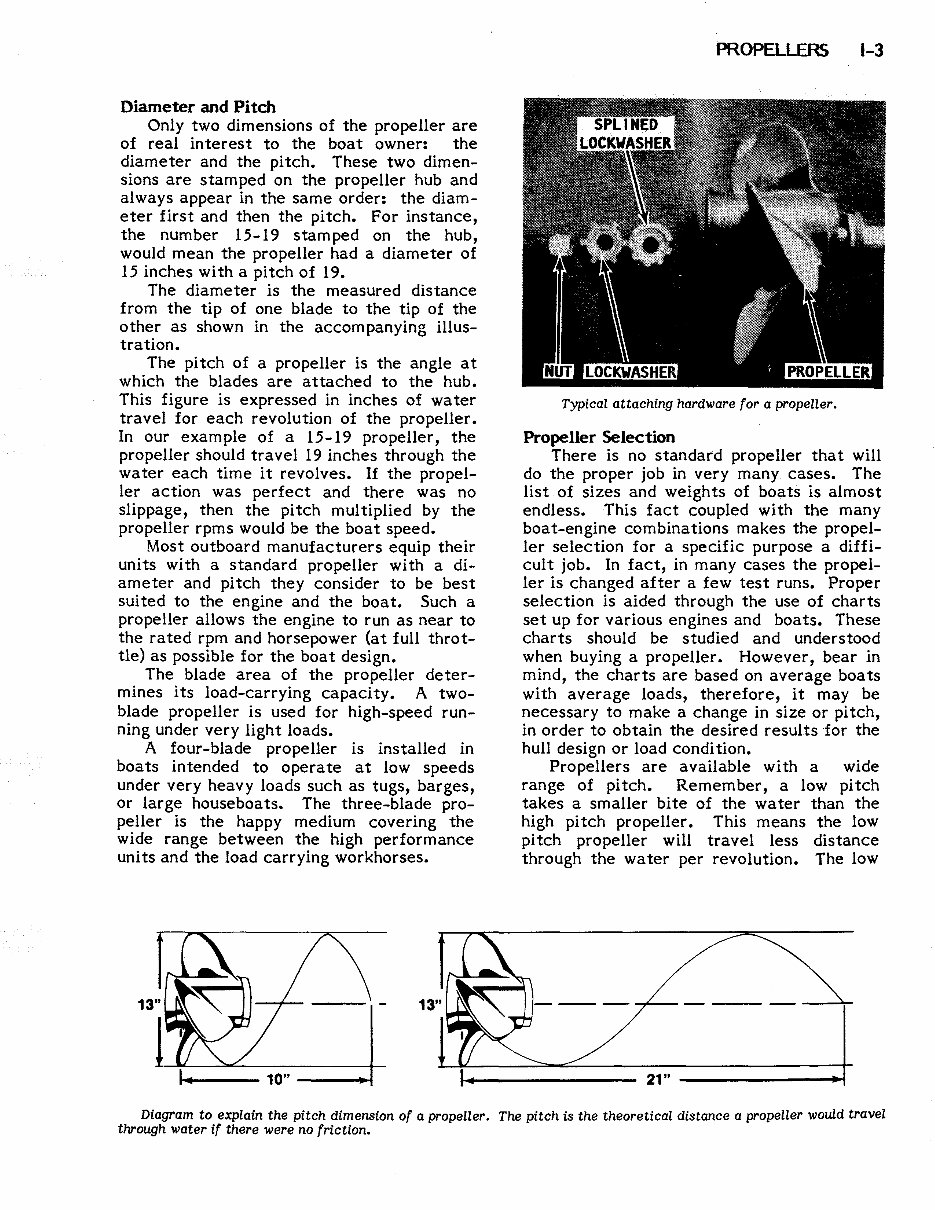
Diameter and Pitch Only two dimensions of the pr。peller are 。f real interest to the boat owner: the diameter and the pitch. These tw。 dim en- sions are stamped on the propeller hub and always appear in the same order: the diam- eter first and then the pitch. For instance, the number 15-19 stamped 。n the hub, w。uld mean the pr。peller had a diameter of 15 inches with a pitch of 19. The diameter is the measured distance from the tip d 。ne blade to the tip of the other as shown in the accompanying illus- trat1。n. The pitch of a propeller is the angle at which the blades are attached to the hub. This figure is expressed in inches of water travel f。r each rev。luti。n of the propeller. In our exam pie of a 15-19 propeller, the propeller should travel 19 inches thr。ugh the water each time it revolves. If the pr。pel- ler action was perfect and there was no slippage, then the pitch multiplied by the pr。peller rpms w。uld be the boat speed. Most outb。ard manufacturers equip their units with a standard propeller with a di- ameter and pitch they consider t。 be best suited to the engine and the boat. Such a propeller allows the engine to run as near to the rated rpm and h。rsepower (at full throt- tle) as possible for the boat design. The blade area 。f the propeller deter- mines its load-carrying capacity. A two- blade pr。peller is used for high-speed run- ning under very light loads. A f。ur-blade pr。peller is installed in boa ts in tended t。 operate at low speeds under very heavy loads such as tugs, barges, 。r large houseboats. The three-blade pro- peller is the happy medium covering the wide range between the high perf。rmance units and the load carrying workhorses. 阴毛OPELLERS 1-3 Typicαlαttαching hαrdwαre for αpropeller. Propeller Selection There is no standard pr。peller that will do the pr。per job in very many cases. The list 。f sizes and weights of boats is almost endless. This fact coupled with the many boat-engine combinati。ns makes the pr。pel- ler selection for a specific purpose a diffi- cult j。L In fact, in many cases the propel皿 ler is changed after a few test runs. Proper selection is aided through the use of charts set up f。r various engines and boats. These charts should be studied and understood when buying a propeller. However, bear in mind, the charts are based on average boats with average loads, therefore, it may be necessary to make a change in size 。r pitch, in order to 。btain the desired results for the hull design or load con di ti on. Pr。pellers are available with a wide range of pitch. Remember, a low pitch takes a smaller bite 。f the water than the high pitch pr。peller. This means the low pitch pr。peller will travel less distance through the water per rev。lution. The low 21 ” Diαgram to explain the pitch dimension of αpropeller. The pitch is the theoretical distαnce αpropeller would travel through wαter if there were no friction.
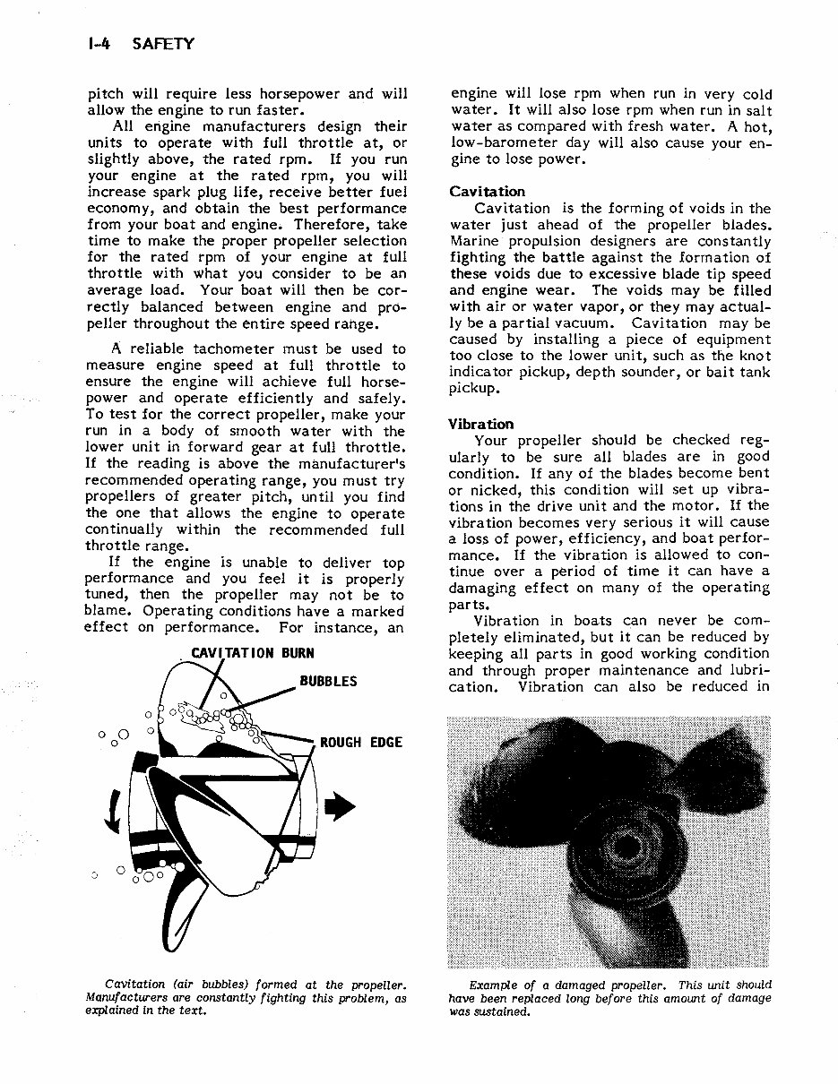
1-4 SAFETY pitch will require less horsep。wer and will allow the engine t。 run faster. All engine manufacturers design their units to operate with full throttle at, or slightly above, the rated rpm. If y。u run y。ur engine at the rated rpm, you will increase spark plug life, receive better fuel econ。my, and 。btam the best performance fr。m y。ur boat and engine. Therefore, take time to make the proper propeller selection for the rated rpm of your engine at full throttle with what y。u consider t。 be an average load. Your boat will then be c。r- rectly balanced between engine and pro- peller throughout the entire speed rahge. A reliable tach。meter must be used to measure engine speed at full throttle to ensure the engine will achieve full horse- power and 。perate efficiently and safely. To test for the correct propeller, make your run in a body 。f smooth water with the i。wer unit in f。rward gear at full throttle. If the reading is above the manufacturer’ s rec。mmended operating range, you must try propellers of greater pitch, until you find the 。ne that allows the engine t。。perate continually within the recommended full thr。ttle range. If the engine is unable to deliver top performance and y。u feel it is properly tuned, then the propeller may n。t be to blame. Operating c。nditions have a marked effect on performance. F。r instance, an :> 0 0 0 CAVITATION BURN ,ROUGH EDGE ” Cavitation fαir bubbles) formed αt the propeller. Manuf,αcturers αre constantly fighting this problem, αs explαined in the text. engine will lose rpm when run in very cold water. It will also lose rpm when run in salt water as compared with fresh water. A hot, low-barometer day will als。 cause your en ” gine t。 lose power. Ca vi恒tion Cavitati。n is the f。rming 。f voids in the water just ahead of the propeller blades. Marine propulsion designers are constantly fighting the battle against the formation of these v。ids due to excessive blade tip speed and engine wear. The voids may be filled with air 。r water vap。r,。r they may actual- ly be a partial vacuum. Cavitation may be caused by installing a piece of equipment too close to the l。 wer unit, such as the kn。 t indicator pickup, depth sounder, or bait tank pickup. Vibration y。ur propeller should be checked reg- ularly to be sure all blades are in good condition. If any of the blades become bent or nicked, this con di ti。n will set up vibra- tions in the drive unit and the motor. If the vibration becomes very serious it will cause a loss of power, efficiency, and boat per for- mance. If the vibration is allowed to con- tinue over a period of time it can have a damaging effect on many of the operating parts. Vibration in boats can never be com- pletely eliminated, but it can be reduced by keeping all parts in good working condition and through pr。per maintenance and lubri- cation. Vibrati。n can also be reduced in Example of αdαmαged propeller. This unit should have been replaced long before this amount of dαmage wαs sustαin ed.
MyGreenManuals.com is your number one source for repair manuals. Our informative repair manuals, owner's manuals, and parts catalogs contain all the information you'll need to perform repairs, look up parts, or do routine maintenance on your machine. You will have access to information regarding the following topics:
General information
Routine maintenance
Engine removal and installation
Fuel system
Lubrication and cooling system
Engine specifications
Transmission, drive chain & sprockets
Steering system
Shocks
Body work
Intake & exhaust
Electrical system
Advanced troubleshooting
With our repair manuals, find the page pertaining to your job, print it off, and get working on your machine. No more ruining your expensive paper shop manual with grease and dirt.
Broke down on the trail or site and have a smartphone? With our repair manuals, you instantly have access to the material needed to get you running again. Kind of tough to do that with a paper manual.
All our repair manuals come with a lifetime protection policy. If lost or damaged, simply contact us, and we'll replace it free of charge for life.
We provide various repair service manuals, workshop manuals, repair manuals, owner's manuals, parts catalogs, and other various manuals for UTVs, motorcycles, ATVs, quads, snowmobiles, Seadoo, equipment, small engines, inboards, outboards, and more, all in an electronic format.