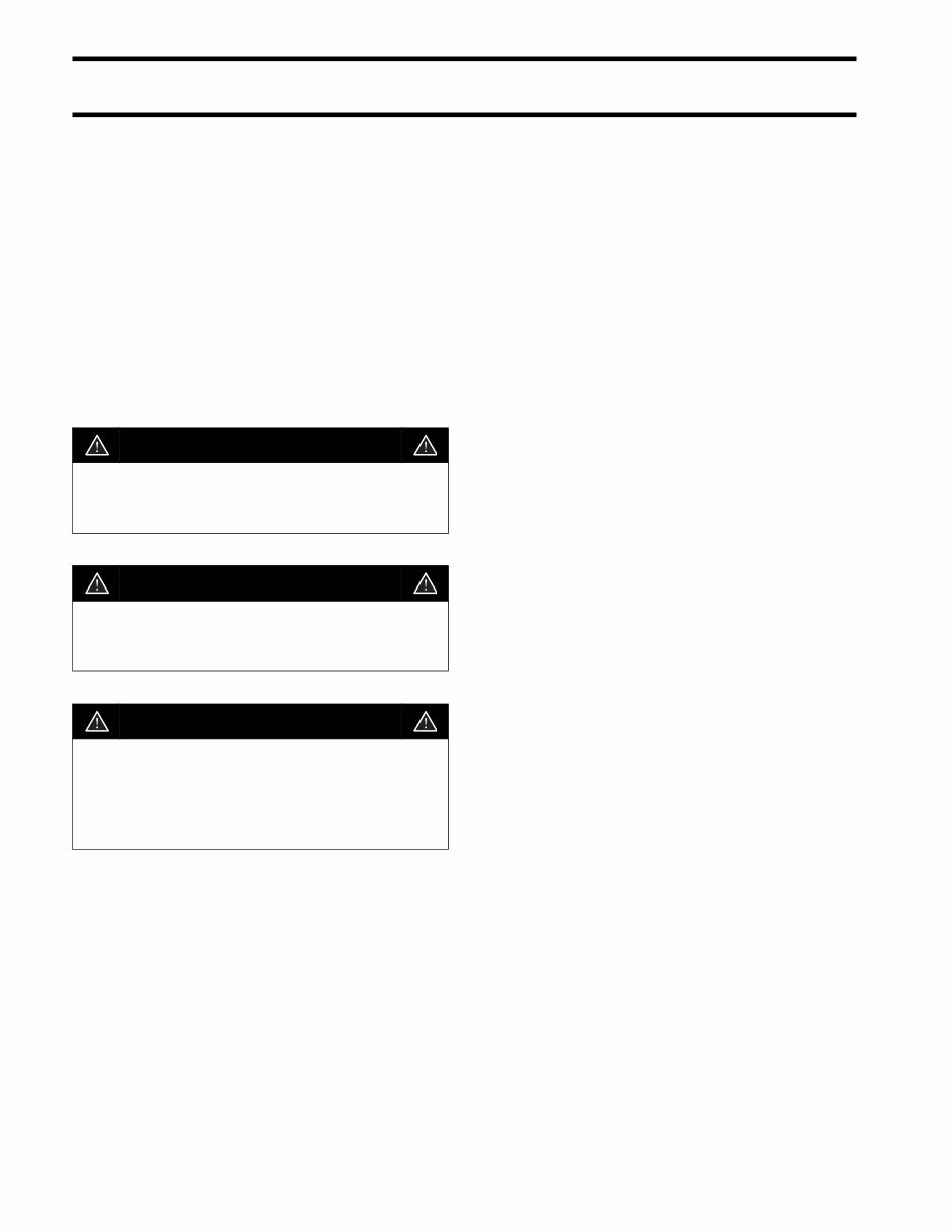
SAFETY INFORMATION Before working on any part of the outboard, read the SAFETY section at the end of this manual. This manual is written for qualified, factory-trained technicians who are already familiar with the use of Evinrude ® /Johnson ® Special Tools. This man- ual is not a substitute for work experience. It is an organized guide for reference, repair, and mainte- nance of the outboard(s). This manual uses the following signal words iden- tifying important safety messages. IMPORTANT: Identifies information that will help prevent damage to machinery and appears next to information that controls correct assembly and operation of the product. These safety alert signal words mean: ATTENTION! BECOME ALERT! YOUR SAFETY IS INVOLVED! Always follow common shop safety practices. If you have not had training related to common shop safety practices, you should do so to protect your- self, as well as the people around you. It is understood that this manual may be trans- lated into other languages. In the event of any dis- crepancy, the English version shall prevail. To reduce the risk of personal injury, safety warn- ings are provided at appropriate times throughout the manual. DO NOT make any repairs until you have read the instructions and checked the pictures relating to the repairs. Be careful, and never rush or guess a service pro- cedure. Human error is caused by many factors: carelessness, fatigue, overload, preoccupation, unfamiliarity with the product, and drugs and alco- hol use, to name a few. Damage to a boat and outboard can be fixed in a short period of time, but injury or death has a lasting effect. When replacement parts are required, use Evinrude/Johnson Genuine Parts or parts with equivalent characteristics, including type, strength and material. Using substandard parts could result in injury or product malfunction. Torque wrench tightening specifications must be strictly followed. Replace any locking fastener (locknut or patch screw) if its locking feature becomes weak. Definite resistance to turning must be felt when reusing a locking fastener. If replacement is specified or required because the locking fastener has become weak, use only authorized Evinrude/Johnson Genuine Parts. If you use procedures or service tools that are not recommended in this manual, YOU ALONE must decide if your actions might injure people or dam- age the outboard. DANGER Indicates an imminently hazardous situa- tion which, if not avoided, WILL result in death or serious injury. WARNING Indicates a potentially hazardous situation which, if not avoided, CAN result in severe injury or death. CAUTION Indicates a potentially hazardous situation which, if not avoided, MAY result in minor or moderate personal injury or property damage. It also may be used to alert against unsafe practices.
DANGER Contact with a rotating propeller is likely to result in serious injury or death. Assure the engine and prop area is clear of people and objects before starting engine or operating boat. Do not allow anyone near a propeller, even when the engine is off. Blades can be sharp and the propeller can continue to turn even after the engine is off. Remove propeller before ser- vicing and when running the outboard on a flushing device. DO NOT run the engine indoors or without adequate ventilation or permit exhaust fumes to accumulate in confined areas. Engine exhaust contains carbon monoxide which, if inhaled, can cause serious brain damage or death. WARNING Wear safety glasses to avoid personal injury, and set compressed air to less than 25 psi (172 kPa). The motor cover and flywheel cover are machinery guards. Use caution when conducting tests on running outboards. DO NOT wear jewelry or loose clothing. Keep hair, hands, and clothing away from rotating parts. During service, the outboard may drop unexpectedly. Avoid personal injury; always support the outboard’s weight with a suitable hoist or the tilt support bracket during service. To prevent accidental starting while servicing, disconnect the battery cables at the battery. Twist and remove all spark plug leads. The electrical system presents a serious shock hazard. DO NOT handle primary or secondary ignition components while outboard is running or flywheel is turning. Gasoline is extremely flammable and highly explosive under certain conditions. Use caution when working on any part of the fuel system. Protect against hazardous fuel spray. Before starting any fuel system service, carefully relieve fuel system pressure. Do not smoke, or allow open flames or sparks, or use electrical devices such as cellular phones in the vicinity of a fuel leak or while fueling. Keep all electrical connections clean, tight, and insulated to prevent shorting or arcing and causing an explosion. Always work in a well ventilated area. Replace any locking fastener (locknut or patch screw) if its locking feature becomes weak. Definite resistance to tightening must be felt when reusing a locking fastener. If replacement is indicated, use only authorized replacement or equivalent.
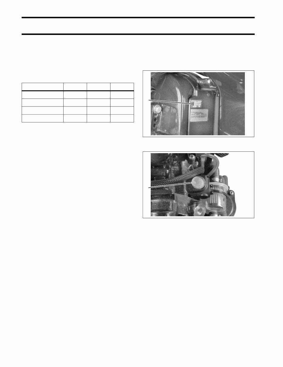
6 INTRODUCTION MODELS COVERED IN THIS MANUAL MODELS COVERED IN THIS MANUAL This manual covers service information on all 3- cylinder, 79 cubic inch, Evinrude E-TEC™ mod- els. Use this manual together with the proper Parts Catalog for part numbers and for exploded views of the outboard, which are a valuable aid to disas- sembly and reassembly. This manual presents the U.S. values and dimensions first and the metric values and dimensions second, inside parenthe- ses ( ). Identifying Model and Serial Numbers Outboard model and serial numbers are located on the swivel bracket and on the powerhead. Model Number Start Shaft Steer E75DPLSUM Electric 20” Remote E90DPLSUM Electric 20” Remote E90DPXSUM Electric 25” Remote E90DSLSUM Electric 20” Remote 1. Model and serial number 002147 1. Serial number 002226 1 1
7 INTRODUCTION MODEL DESIGNATION MODEL DESIGNATION B E 90 DPL SU M PREFIX STYLE: J = Johnson E = Evinrude HORSEPOWER LENGTH: = 15” Std. L = 20” Long Y = 22.5” Special X = 25” X-long Z = 30” XX-long MODEL YR: I = 1 N = 2 T = 3 R = 4 O = 5 D = 6 U = 7 C = 8 E = 9 S = 0 Ex: SU = 2007 MODEL RUN or SUFFIX DESIGN FEATURES: AP = Advanced Propulsion B = Blue Paint C = Counter Rotation D = Evinrude E-TEC™ E = Electric Start w/Remote Steering F = Direct-Injection G = Graphite Paint H = High Output J = Jet Drive M = Military P = Power Trim and Tilt R = Rope Start w/Tiller Steering S = Saltwater Edition T = Tiller Steering TE = Tiller Electric V = White Paint W = Commercial Model
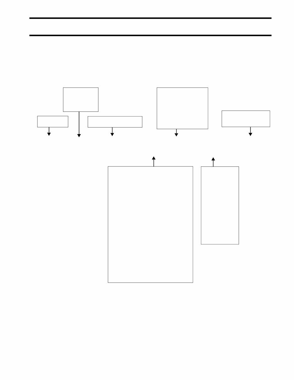
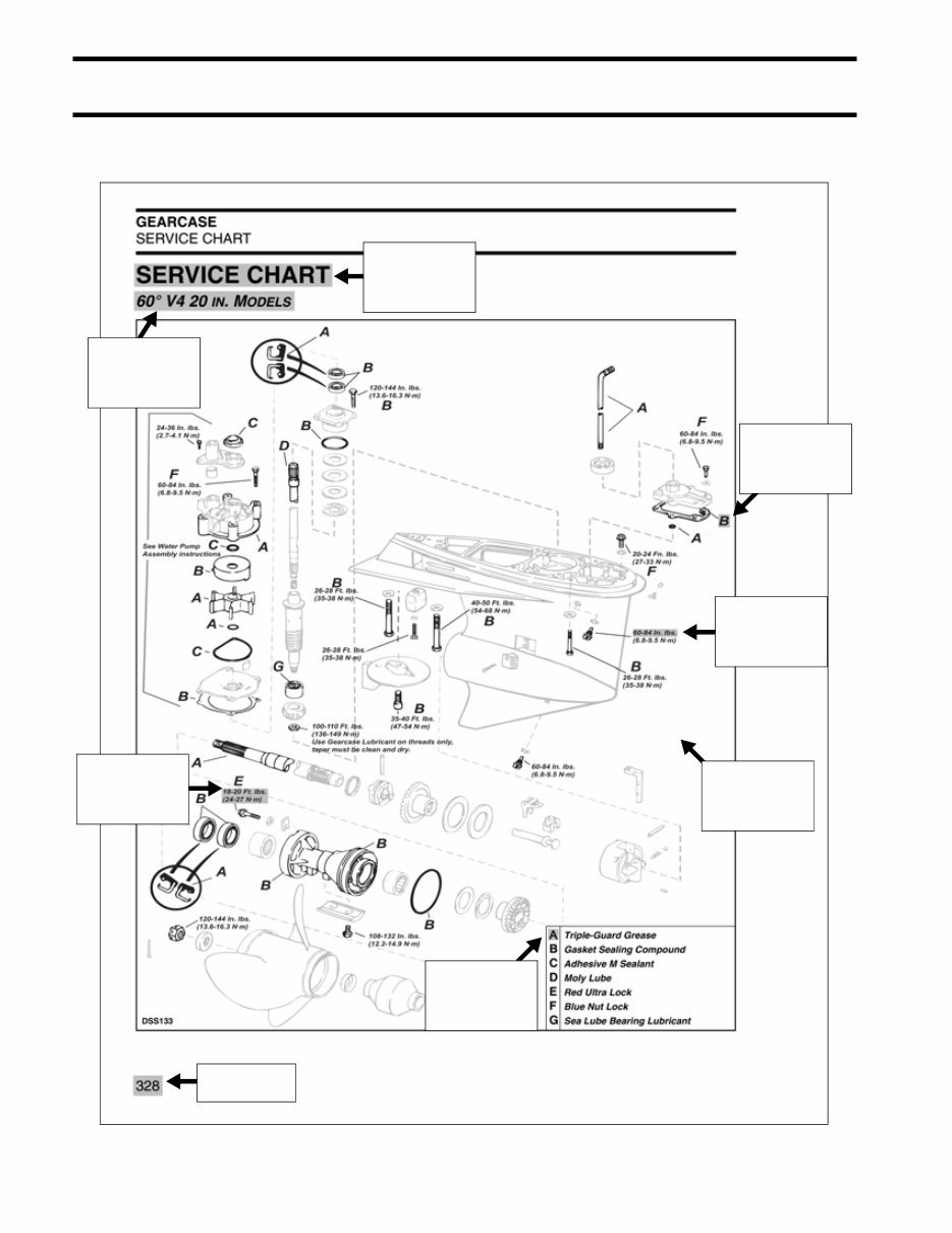
8 INTRODUCTION TYPICAL PAGE – A TYPICAL PAGE – A Page Number Bold letter indicates liquid product to be applied to a surface Pay attention to torque specifications. Some units appear as in. lbs. Use appropriate torque. Tightening torque for a fastener. Subsection title indicates beginning of the subsection. Italic subheading above Service Chart indicates pertaining models. Indicates list corresponding to applicable letter in exploded view of the Service Chart. Exploded view of Service Chart assists in identifying parts and positions
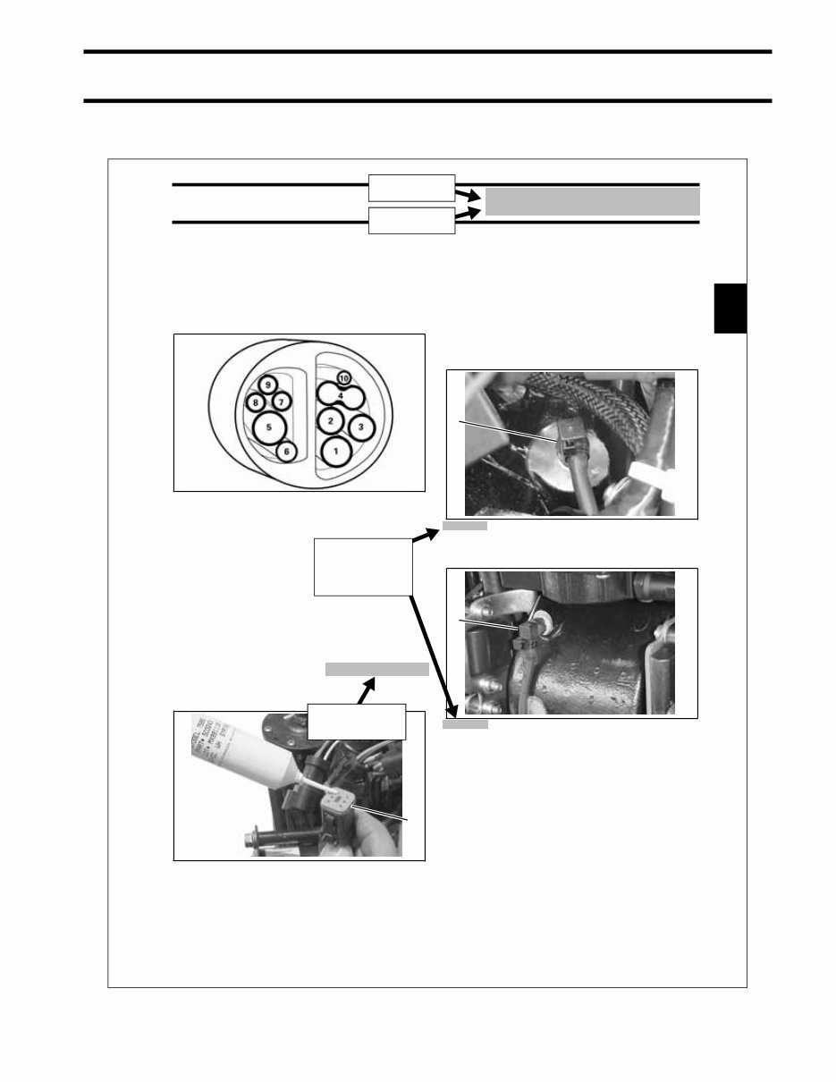
INTRODUCTION TYPICAL PAGE – B 9 TYPICAL PAGE – B 47 INSTALLATION AND PREDELIVERY OUTBOARD RIGGING PROCEDURE 2 Cable, Hose, and Wire Routing Route all hoses, control cables, and wiring through a protective sleeve or conduit into the boat and through the grommet. Refer to the following diagram to ensure proper positioning of rigging components in grommet. Connect outboard main wire harness to boat main wire harness. Before installing electrical connectors, check that the seal is in place. Clean off any dirt from con- nectors. Apply a light coat of Electrical Grease™ to the seal. Push connectors together until latched. If a water pressure gauge is to be used, install the water pressure hose fitting in the cylinder block. Use Pipe Sealant with Teflon (P/N 910048) on the threads of the hose fitting. Refer to installation instructions supplied with gauge. Route the water pressure hose through cover grommet with oil tank sending unit harness. Route hose along battery cables toward the back of the powerhead. Use tie straps to fasten in place. If temperature gauge is to be used, route sending unit wire through grommet with hose for water pressure gauge. Follow the path of battery cables. Provide adequate length to reach cylinder head. Refer to installation instructions supplied with gauge. 1. Fuel supply hose 2. Oil return hose 3. Oil supply hose 4. Battery cables 5. Main wire harness (MWS) 6. Throttle cable 7. Shift cable 8. Oil tank sending unit harness 9. Water pressure hose 10. Accessory charge wire 000084 1. Seal DP0824 1 V4 Models 1. Water pressure fitting location: top, starboard side of cylinder/crankcase assembly, below throttle position sensor. DP0827 V6 Models 1. Water pressure fitting location: rear of cylin- der/crankcase assembly DP0828 1 1 Section Title Subsection Title Model specific illustrations designated with image captions Products and lubricants italicized
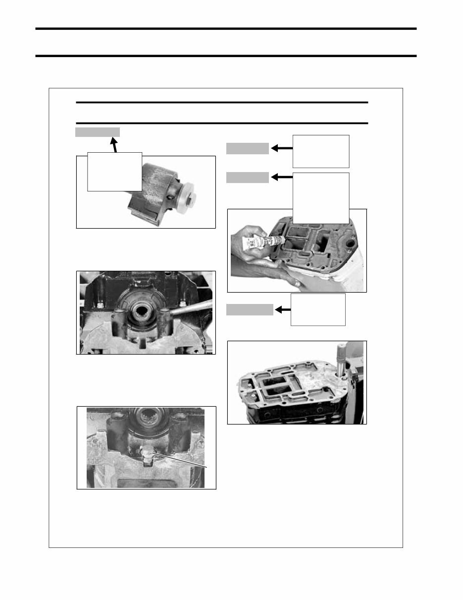
10 INTRODUCTION TYPICAL PAGE – C TYPICAL PAGE – C 272 POWERHEAD INSTALLATION IMPORTANT: The motor mount, washer, and screw are serviced as an assembly. Do not disas- semble. Installation Place mount assemblies in position, with flats fac- ing away from each other. Apply Extreme Pressure Grease to all sides of retainer and install between mounts. Apply Nut Lock to retainer screw, install the screw, and torque to 15 to 20 ft. lbs. (20 to 27 N·m). INSTALLATION V4 MODELS Install base gasket dry. Do not use Permatex No. 2 or Gasket Sealing Compound. V6 MODELS Apply Permatex No. 2 gasket sealant to inner exhaust housing flange. Coat both sides of a new base gasket with Gasket Sealing Compound. ALL MODELS Install a new base gasket on adapter. To ensure proper sealing, mating surfaces must be clean and free of oil, grease, and foreign matter. Coat the driveshaft splines with Moly Lube. Do not apply lubricant to end of driveshaft. 39820 49557 1. Mount retainer screw 49556 1 23079 23497 Title in italics indicates a procedure concerning a particular model Title indicates from this point, All Models are concerned Denotes necessary step or information to prevent damage or control correct procedure Title indicates the procedure specific to V4 Models is finished. From this point, this particular procedure concerns V6 Models.
You're Reading a Preview
What's Included?
Lifetime Access
Fast Download Speeds
Online & Offline Access
Access PDF Contents & Bookmarks
Full Search Facility
Print one or all pages of your manual
$41.99
2007 Johnson Evinrude Outboard 75hp - 90hp E-Tec Service & Repair Manual
Thank you for considering this comprehensive Service Repair Workshop Manual for the Johnson Evinrude Outboard 75hp-90hp E-Tec model from 2007.
This manual is an invaluable resource for both professional mechanics and DIY enthusiasts, covering every service and repair procedure with easy-to-follow step-by-step instructions and detailed pictures.
By utilizing this manual, you can save a significant amount of money by performing your own repairs. It provides the flexibility to print specific pages, chapters, or the entire manual, and can also be saved to your tablet or smartphone for easy access.
All models, engines, trim, and transmission types are included in this manual, ensuring comprehensive coverage for all your repair needs.
From A to Z, this high-quality Service Repair Workshop Manual encompasses every repair and service procedure, making it an essential tool for maintaining your Johnson Evinrude Outboard.
Compatible with all PC and MAC computers, tablets, and mobile phones, this downloadable manual requires only Adobe Reader, which is commonly pre-installed or available for free download.
Upon payment via Visa, MasterCard, or PayPal, the manual will be instantly delivered to the email address provided during checkout, ensuring prompt access to the valuable information it contains.
Rest assured, customer satisfaction is guaranteed with this comprehensive Service Repair Workshop Manual.
Recently Viewed
5,521,897Happy Clients
2,594,462eManuals
1,120,453Trusted Sellers
15Years in Business
Price:
Actual Price:
2007 Johnson Evinrude Outboard 75hp - 90hp E-Tec Service & Repair Manual






 Lifetime Access




