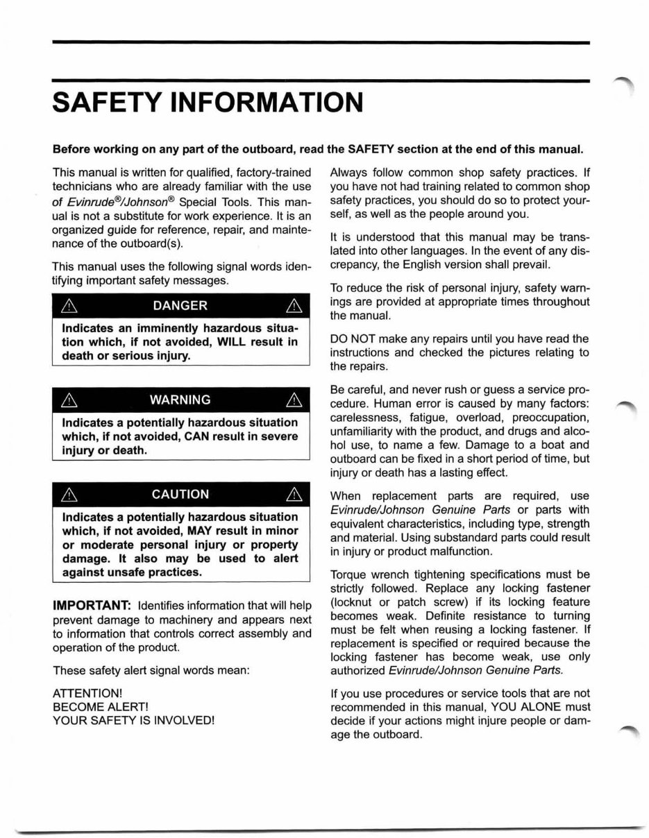
SAFETY INFORMATION Before working on any part of the outboard, read the SAFETY section at the end of this manual. This manual is written for qualified, factory-trained technicians who are already familiar with the use of Evinrude®/Johnson® Special Tools. This man- ual is not a substitute for work experience. It is an organized guide for reference, repair, and mainte- nance of the outboard(s). This manual uses the following signal words iden- tifying important safety messages. 6 DANGER 6 Indicates an imminently hazardous situa- tion which, if not avoided, WILL result in death or serious injury. 6 WARNING 6 Indicates a potentially hazardous situation which, if not avoided, CAN result in severe injury or death. 6 CAUTION 6 Indicates a potentially hazardous situation which, if not avoided, MAY result in minor or moderate personal injury or property damage. It also may be used to alert against unsafe practices. IMPORTANT: Identifies information that will help prevent damage to machinery and appears next to information that controls correct assembly and operation of the product. These safety alert signal words mean: ATTENTION! BECOME ALERT! YOUR SAFETY IS INVOLVED! Always follow common shop safety practices. If you have not had training related to common shop safety practices, you should do so to protect your- self, as well as the people around you. It is understood that this manual may be trans- lated into other languages. In the event of any dis- crepancy, the English version shall prevail. To reduce the risk of personal injury, safety warn- ings are provided at appropriate times throughout the manual. DO NOT make any repairs until you have read the instructions and checked the pictures relating to the repairs. Be careful, and never rush or guess a service pro- cedure. Human error is caused by many factors: carelessness, fatigue, overload, preoccupation, unfamiliarity with the product, and drugs and alco- hol use, to name a few. Damage to a boat and outboard can be fixed in a short period of time, but injury or death has a lasting effect. When replacement parts are required, use Evinrude/Johnson Genuine Parts or parts with equivalent characteristics, including type, strength and material. Using substandard parts could result in injury or product malfunction. Torque wrench tightening specifications must be strictly followed. Replace any locking fastener (locknut or patch screw) if its locking feature becomes weak. Definite resistance to turning must be felt when reusing a locking fastener. If replacement is specified or required because the locking fastener has become weak, use only authorized Evinrude/Johnson Genuine Parts. If you use procedures or service tools that are not recommended in this manual, YOU ALONE must decide if your actions might injure people or dam- age the outboard.
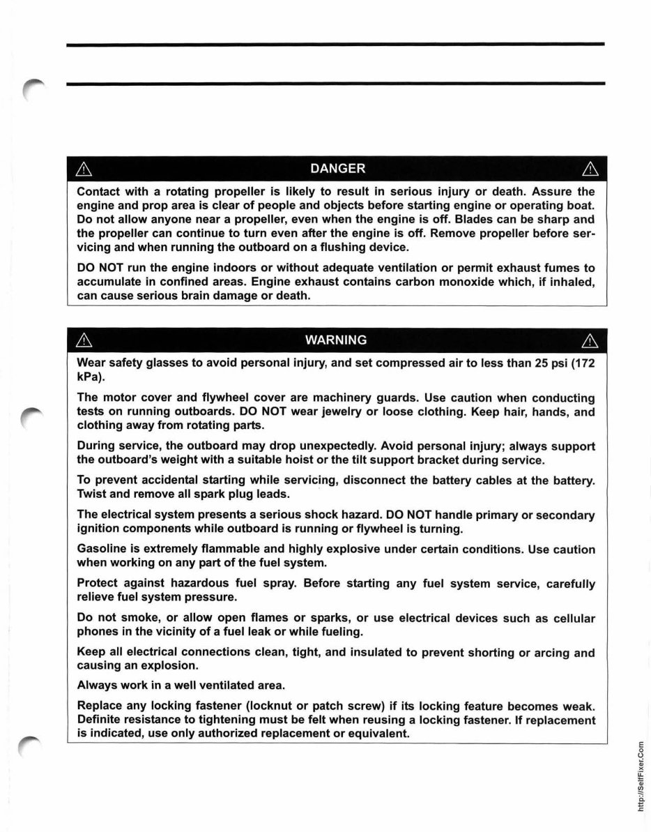
~ DANGER ~ Contact with a rotating propeller is likely to result in serious injury or death. Assure the engine and prop area is clear of people and objects before starting engine or operating boat. Do not allow anyone near a propeller, even when the engine is off. Blades can be sharp and the propeller can continue to turn even after the engine is off. Remove propeller before ser- vicing and when running the outboard on a flushing device. DO NOT run the engine indoors or without adequate ventilation or permit exhaust fumes to accumulate in confined areas. Engine exhaust contains carbon monoxide which, if inhaled, can cause serious brain damage or death. ~ WARNING ~ Wear safety glasses to avoid personal injury, and set compressed air to less than 25 psi (172 kPa). The motor cover and flywheel cover are machinery guards. Use caution when conducting tests on running outboards. DO NOT wear jewelry or loose clothing. Keep hair, hands, and clothing away from rotating parts. During service, the outboard may drop unexpectedly. Avoid personal injury; always support the outboard's weight with a suitable hoist or the tilt support bracket during service. To prevent accidental starting while servicing, disconnect the battery cables at the battery. Twist and remove all spark plug leads. . The electrical system presents a serious shock hazard. DO NOT handle primary or secondary ignition components while outboard is running or flywheel is turning. Gasoline is extremely flammable and highly explosive under certain conditions. Use caution when working on any part of the fuel system. Protect against hazardous fuel spray. Before starting any fuel system service, carefully relieve fuel system pressure. Do not smoke, or allow open flames or sparks, or use electrical devices such as cellular phones in the vicinity of a fuel leak or while fueling. Keep all electrical connections clean, tight, and insulated to prevent shorting or arcing and causing an explosion. Always work in a well ventilated area. Replace any locking fastener (locknut or patch screw) if its locking feature becomes weak. Definite resistance to tightening must be felt when reusing a locking fastener. If replacement is indicated, use only authorized replacement or equivalent. E o U Qj )( ~ Qj ~ ii E
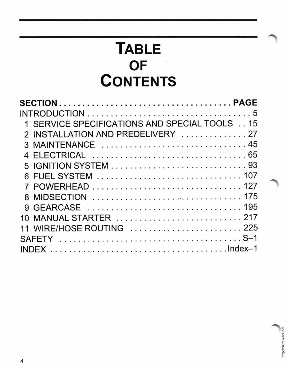
TABLE OF CONTENTS SECTION ..................................... PAGE- INTRODUCTION ................................... 5 1 SERVICE SPECIFICATIONS AND SPECIAL TOOLS .. 15 2 INSTALLATION AND PREDELIVERY .............. 27 3 MAINTENANCE ............................... 45 4 ELECTRICAL ................................. 65 5 IGNITION SYSTEM ............................. 93 6 FUEL SYSTEM ............................... 107 7 POWERHEAD ................................ 127 8 MIDSECTION ................... . ............. 175 9 GEARCASE ................................. 195 10 MANUAL STARTER ........................... 217 11 WIRE/HOSE ROUTING ........................ 225 SAFETY .................. . .................... S-1 INDEX ...................................... lndex-1 4
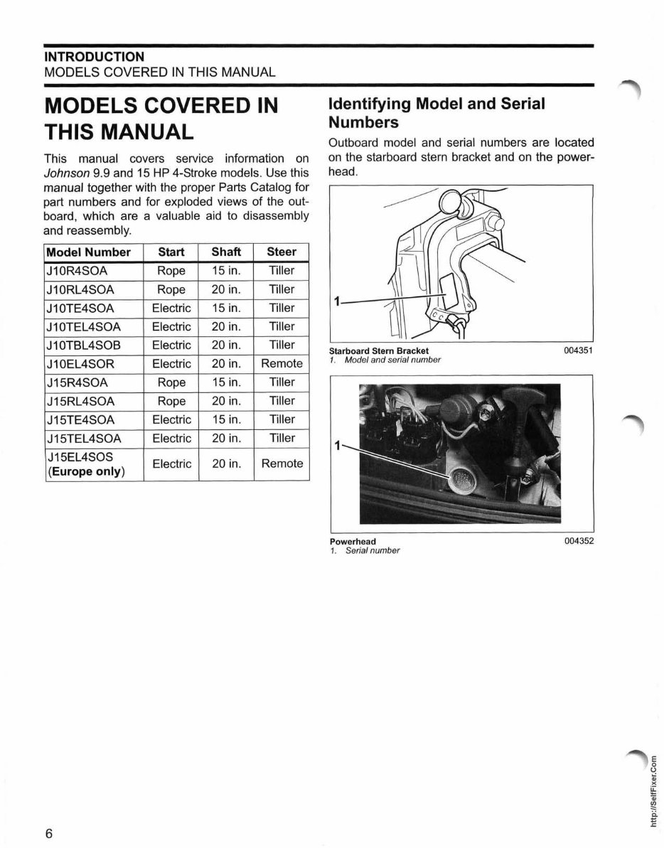
INTRODUCTION MODELS COVERED IN THIS MANUAL MODELS COVERED IN THIS MANUAL This manual covers service information on Johnson 9.9 and 15 HP 4-Stroke models. Use this manual together with the proper Parts Catalog for part numbers and for exploded views of the out- board, which are a valuable aid to disassembly and reassembly. Model Number Start Shaft Steer J10R4S0A Rope 15 in. Tiller J10RL4S0A Rope 20 in. Tiller J10TE4S0A Electric 15 in. Tiller J10TEL4S0A Electric 20 in. Tiller J10TBL4S0B Electric 20 in. Tiller J10EL4S0R Electric 20 in. Remote J15R4S0A Rope 15 in. Tiller J15RL4S0A Rope 20 in. Tiller J15TE4S0A Electric 15 in. Tiller J15TEL4S0A Electric 20 in. Tiller J15EL4S0S Electric 20 in. Remote (Europe only) 6 Identifying Model and Serial Numbers Outboard model and serial numbers are located on the starboard stern bracket and on the power- head. 1_--:in-ITTI Starboard Stern Bracket 004351 1. Model and serial number 1 Powerhead 004352 1. Serial number E o U Qj )( ~ Qj ~ ii E
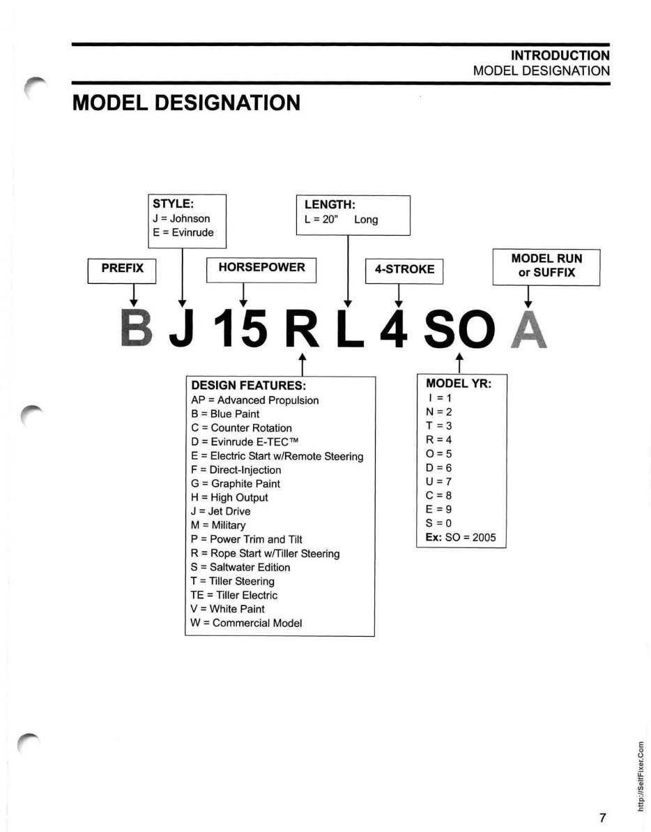
INTRODUCTION MODEL DESIGNATION MODEL DESIGNATION STYLE: J = Johnson E = Evinrude LENGTH: L = 20" Long I PREFt I " I HORSEPOWER I ,I 4-SiROKE I B J 15 R L 4 SO ~_----1t_------, t MODEL YR: DESIGN FEATURES: AP = Advanced Propulsion B = Blue Paint C = Counter Rotation D = Evinrude E-TECTM E = Electric Start w/Remote Steering F = Direct-Injection G = Graphite Paint H = High Output J = Jet Drive M = Military P = Power Trim and Tilt R = Rope Start wlTiller Steering S = Saltwater Edition T = Tiller Steering TE = Tiller Electric V = White Paint W = Commercial Model I = 1 N=2 T = 3 R=4 0=5 D=6 U=7 C=8 E = 9 S=O Ex: SO = 2005 MODEL RUN or SUFFIX 7 E o U Qj )( ~ Qj ~ ii E
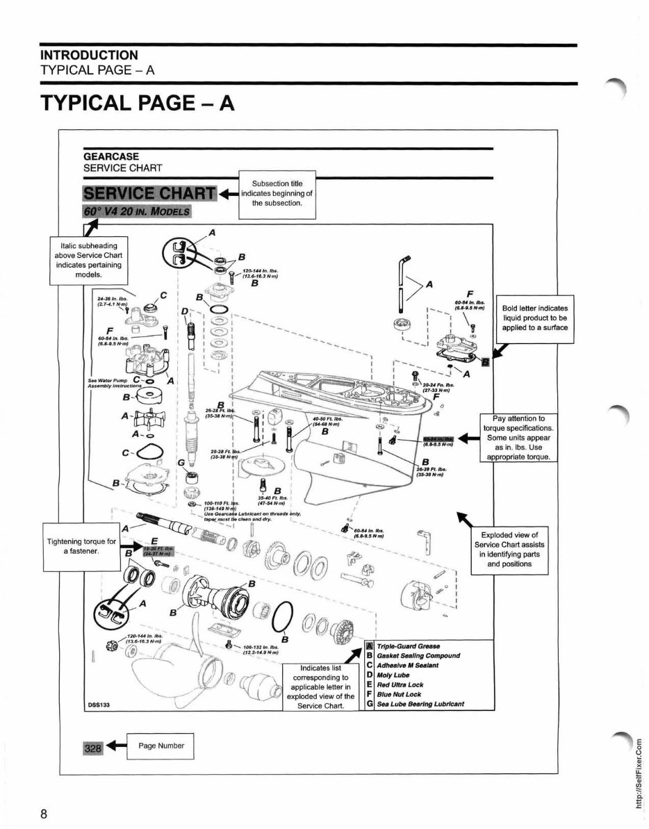
INTRODUCTION TYPICAL PAGE - A TYPICAL PAGE - A GEARCASE SERVICE CHART Subsection title indicates beginning of the subsection. Italic subheading above Service Chart indicates pertaining models. ~ n ~~~1uln" b' ! ! l1/ (13.6. 1tJ.3 N-m) ! /6--! B B ~f{-" I "'~_./ , D ,~~ 0 , \~ : @,----- ! t -- f - ! 1<:.;:::::)' I 1 24--361n /bs /C (2'7"" H~~ ~/nlbs ~' (6.8-".5 No m) t:t I I I -. -I I ~ .: : SeeWat$l'Pump C-o A I _._ : Assembly Instructlo~ I ". l B -~ I ' A -~ ;~~. A-o :' C -o i'~ ~l:G ···· B -n~~ t!J ~ , ("5' '"" J ~ f 3540 Ft. lb •. ) .... ", _! @-100-110Ft.jS. (47. 54N-m) i , -- " ! (13tj.140N-) ! ... ~---1 __ .....L ___ ~ - t8p4t(must d. elun and dry. ! "_ " ~ ..... Usa Geaf'C 8L.Ubricantonthre. dllbnIY,. A -- ~-1 U"- tI ...... Sf)..U In. lb •. 8 Tightening torque for '.jj {} r~ 'lC}"- , -. ~'- ~ __ _ (, .B-9., N'm) a fastener. ~ f:;' r::,.' - " '- {~/ ~ ((j)@ corresponding to applicable letter in exploded view of the DSSl33 Service Chart . .., Page Number Triple-Guard Gl'ItBse Gasket Sealing Compound Adhealve If Ses/anl lfo/yLubs R«I Ultra Lock Blue Nut Lock Sea Lube Bearing Lubrlc8nt Bold letter indicates liquid product to be applied to a surface Pay attention to torque specifications. Some units appear as in. Ibs. Use Exploded view of Service Chart assists in identifying parts and positions E o U Qj )( ~ Qj ~ ii E
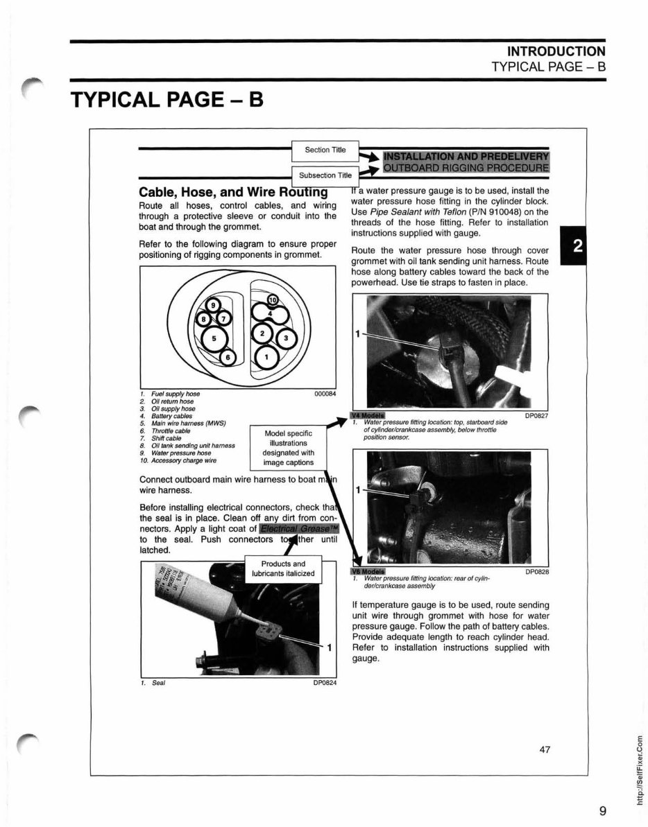
TYPICAL PAGE - B Section Title Cable, Hose, and Wire Rou 1n9 Route all hoses, control cables, and wiring through a protective sleeve or conduit into the boat and through the grommet. Refer to the following diagram to ensure proper positioning of rigging components in grommet. 1. Fuel supply hose 2. Oil return hose 3. Oil supply hose 4. Battery cables 5. Main wire harness (MWS) 6. Throttle cable 7. Shift cable 8. Oil tank sending unit harness 9. Water pressure hose 10. Accessory charge wire Model specific illustrations designated with image captions 000084 Connect outboard main wire harness to boat wire harness. Before installing electrical connectors, check the seal is in place. Clean Off !!l! d! irt ! fr ~ o! m ~!! nectors. Apply a light coat of to the seal. Push connectors latched. 1. Seal INTRODUCTION TYPICAL PAGE - B a water pressure gauge is to be used, install the water pressure hose fitting in the cylinder block. Use Pipe Sealant with Teflon (PIN 910048) on the threads of the hose fitting. Refer to installati on instructions supplied with gauge. Route the water pressure hose through cover grommet with oil tank sending unit harness. Route hose along battery cables toward the back of the powerhead. Use tie straps to fasten in place. pressure fitting loca tion: top, starboard side of cylinder/crankcase assembl y, below thr ottle positi on sensor. If temperature gauge is to be used, route sending unit wire through grommet with hose for water pressure gauge. Follow the path of battery cables. Provide adequate length to reach cylinder head. Refer to installation instructions supplied with gauge. 47 9
The repair manual for Johnson Evinrude 4 Stroke 9.9-15HP outboards 2005 is a valuable resource for both professional technicians and do-it-yourself mechanics. It is designed to provide comprehensive guidance for maintaining and repairing the vehicle or engine.
This manual is suitable for individuals with basic knowledge in electrical and mechanical concepts. It covers a wide range of topics including engine removal, wiring diagrams, general information, specifications, lubrication points, oil types, periodic maintenance, tune-up procedures, disassembly, reassembly, fuel and lubrication systems, electrical system, ignition, chassis, and more.
The manual offers step-by-step repair procedures, critical specifications, illustrations, maintenance, disassembly, assembly, cleaning, and reinstalling procedures. It is available in English language and can be zoomed in/out. The file format is PDF, compatible with all versions of Windows and Mac, and can be instantly delivered. It requires Adobe Reader and Win for access.
Whether you obtain a paper manual or the digital version, the features remain the same. The digital version offers the convenience of instant access and can be downloaded straight to your computer, providing quick solutions for maintaining and repairing Johnson Evinrude 4 Stroke 9.9-15HP outboards 2005.
The manual is an essential reference for anyone looking to make informed decisions about maintaining and repairing Johnson Evinrude 4 Stroke 9.9-15HP outboards 2005.
Engine Removal
Wiring Diagrams
General Information
Specifications
Lube Points
Oil Types
Periodic Maintenance and Tune-Up Procedures
Engine Servicing
Disassembly
Reassembly
Fuel and Lubrication Systems
Electrical System
Ignition
Chassis
Charging
Starter
Battery
Switches
Wheels
Brakes
Steering
Suspension
Axles
Chassis Assembly
Servicing Information
Service Data
Wire/Cable/Hose Routing
Tools
Tightening Torques
Complete Engine Service
Fuel System Service
All Factory Repair Procedures
Gearbox
Exhaust System
Suspension
Fault Finding
Clutch Removal and Installation
Transmission
Front Suspension
Bodywork
Gearbox Service
Gearbox Removal and Installation
Cooling System
Detailed Specifications
Factory Maintenance Schedules
Electrics
Engine Firing Order
Brake Servicing Procedures
U-Joint Service Procedures
CV Joint Service Procedures
Timing Chain Service
Exhaust Service
Plus Lots More
Recently Viewed
5,521,897Happy Clients
2,594,462eManuals
1,120,453Trusted Sellers
15Years in Business
Price:
Actual Price:
2005 Johnson Evinrude 4 Stroke 9.9-15HP Outboards Service & Repair Manual