1998 EVINRUDE JOHNSON 50HP 2-STROKE OUTBOARD Factory Service & Work Shop Manual
What's Included?
Lifetime Access
Fast Download Speeds
Online & Offline Access
Access PDF Contents & Bookmarks
Full Search Facility
Print one or all pages of your manual
General Informati Tools and Techniq Troubleshooti Lubrication, Maintenance and ~une- I I Synchronization and Linkage Adjustmerits I I I Fuel Systd I Ignition and Electrical System I Power Hea Lower Gearcase and Jet Drive units Trim and Tilt Systerfis I Oil Injection Systems Rope Starters and Remote Controls I I ~ndk I Wiring ~iagra$s I www.manuals-n-more.com.au i General Informatdm Tools and Techniqu~s I TroubleShootirg I Lubrication, Maintenance and Tune-I,Ip I Synchronization and Linkage Adjustments fuel System Ignition and E.lectrical Syste .... s i Power He~d I Lower Gearcase and Jet Drive Un~s Trim and Tilt Systems I Oil Injection Systems Rope Starters and Remote Controls I ! i Index i I Wiring Diagraq..s ! I I
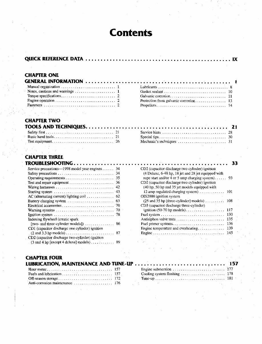
Chapter One General Information This detailed, comprehensive manual contains complete information covering maintenance, repair and overhaul. Hundreds of photos and drawings guide you throughout every proce- dure. Troubleshooting, tune-up, maintenance and repair are not d~fficul if you know what tools and equipment to use and what to do. Anyone not afiaid to get their hands dirty, of average in- telligence and with some mechanical ability can perform most of the procedures in this manual. See Chapter Two for more information on tools and techniques. A shop manual is a reference. You want to be able to find information quickly. Clymer books are designed with you in mind. All chapters are thumb tabbed and important items are indexed at the end of the manual. All procedures, tables, photos and instructions in this manual assume the reader may be worlung on the machine or us- ing the manual for the first time. Keep the manual in a handy place in your tool- box or boat. It will help you to better understand how your boat runs, lower repair and maintenance costs and generally increase your enjoyment of your boat. MANUAL ORGANIZATION This chapter provides general information useful to boat owners and marine mechanics. Chapter Two discusses the tools and tech- niques for preventative maintenance, trouble- shooting and repair. Chapter Three provides troubleshooting and testing procedures for all systems and individual components. Following chapters describe specific systems, providing disassembly, inspection, assembly and adjustment procedures in simple step-by- step form. Specifications concerning a specific system are included at the end of the appropriate chapter. www.manuals-n-more.com.au Chapter One General Information This detailed, comprehensive manual contains complete information covering maintenance, repair and overhaul. Hundreds of photos and drawings guide you throughout every proce- dure. Troubleshooting, tune-up, maintenance and repair are not difficult if you know what tools and equipment to use and what to do. Anyone not afraid to get their hands dirty, of average in- telligence and with some mechanical ability can perform most of the procedures in this manual. See Chapter Two for more information on tools and techniques. A shop manual is a reference. You want to be able to fmd information quickly. Clymer books are designed with you in mind. All chapters are thumb tabbed and important items are indexed at the end of the manual. All procedures, tables, photos and instructions in this manual assume the reader may be working on the machine or us- ing the manual for the fIrst time. Keep the manual in a handy place in your tool- box or boat. It will help you to better understand how your boat runs, lower repair and maintenance costs and generally increase your enjoyment of your boat. MANUAL ORGANIZATION This chapter provides general information useful to boat owners and marine mechanics. Chapter Two discusses the tools and tech- niques for preventative maintenance, trouble- shooting and repair. Chapter Three provides troubleshooting and testing procedures for all systems and individual components. Following chapters describe specifIc systems, providing disassembly, inspection, assembly and adjustment procedures in simple step-by- step form. Specifications concerning a specific system are included at the end of the appropriate chapter.
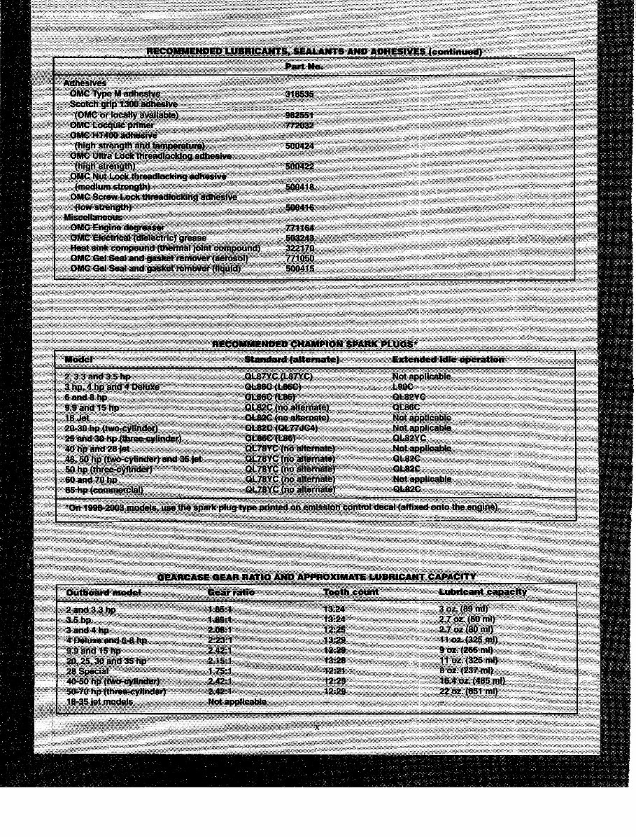
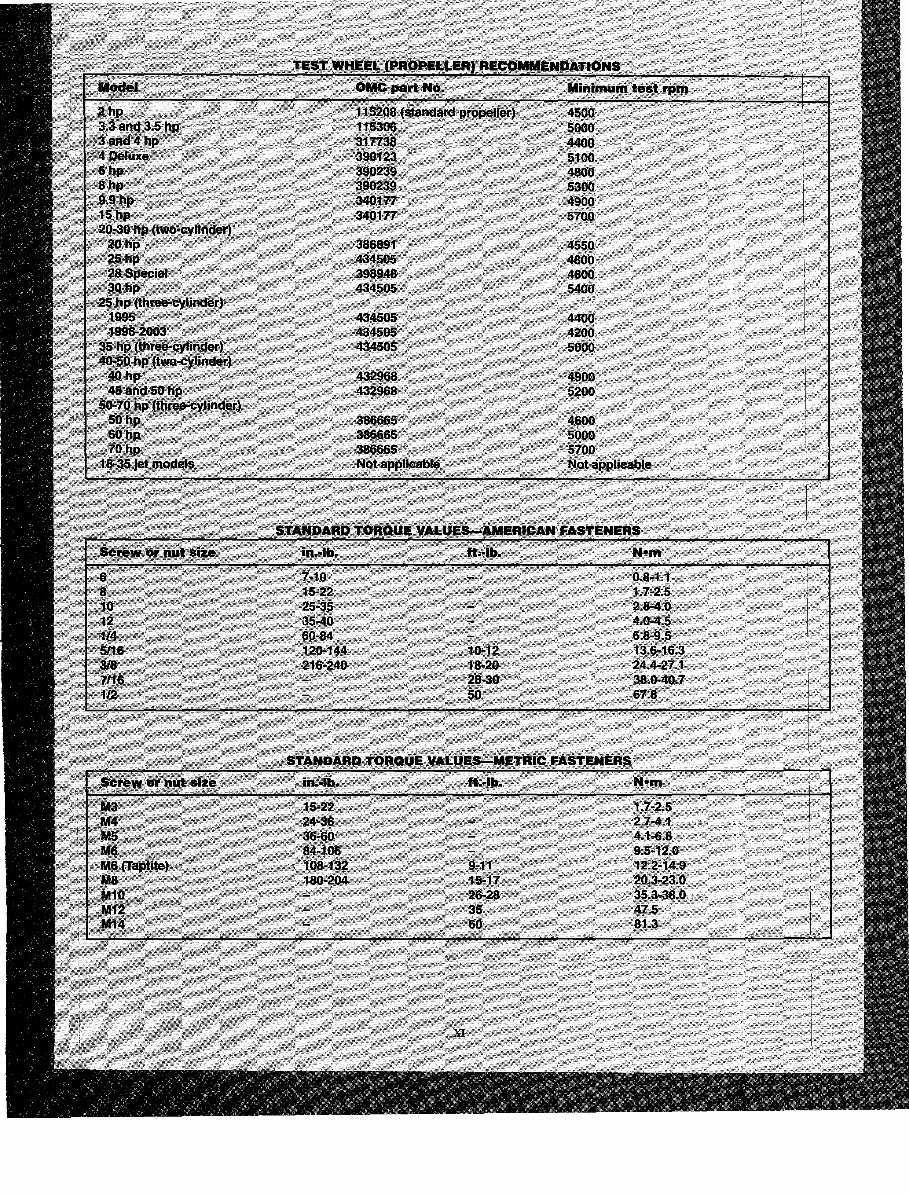
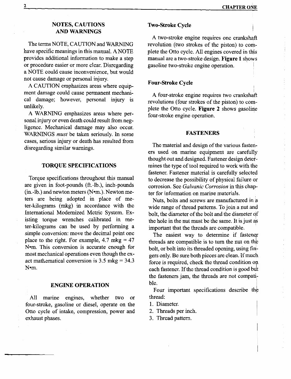
CHAPTER ONE NOTES, CAUTIONS AND WARNINGS The terms NOTE, CAUTION and WARNING have specific meanings in this manual. A NOTE provides additional information to make a step or procedure easier or more clear. Disregarding a NOTE could cause inconvenience, but would not cause damage or personal injury. A CAUTION emphasizes areas where equip- ment damage could cause permanent mechani- cal damage; however, personal injury is unlikely. A WARNING emphasizes areas where per- sonal injury or even death could result from neg- ligence. Mechanical damage may also occur. WARNINGS must be taken seriously. In some cases, serious injury or death has resulted from disregarding similar warnings. TORQUE SPECIFICATIONS Torque specifications throughout this manual are given in foot-pounds (ft.-lb.), inch-pounds (in.-lb.) and newton meters (N-m.). Newton me- ters are being adopted in place of me- ter-kilograms (mkg) in accordance with the International Modernized Metric System. Ex- isting torque wrenches calibrated in me- ter-lulograms can be used by performing a simple conversion: move the decimal point one place to the right. For example, 4.7 mkg = 47 N-m. This conversion is accurate enough for most mechanical operations even though the ex- act mathematical conversion is 3.5 mkg = 34.3 N-m. ENGINE OPERATION All marine engines, whether two or four-stroke, gasoline or diesel, operate on the Otto cycle of intake, compression, power and exhaust phases. Wo-Stroke Cycle A two-stroke engine requires one crankshaft revolution (two strokes of the piston) to com- plete the Otto cycle. All engines covered in this manual are a two-stroke design. Figure 1 shows gasoline two-stroke engine operation. Four-Stroke Cycle A four-stroke engine requires two crankshaft revolutions (four strokes of the piston) to com- plete the Otto cycle. Figure 2 shows gasoline four-stroke engine operation. FASTENERS The material and design of the various fasten- ers used on marine equipment are carefully thought out and designed. Fastener design deter- mines the type of tool required to work with the fastener. Fastener material is carefully selected to decrease the possibility of physical failure or corrosion. See Galvanic Corrosion in this chap- ter for information on marine materials. Nuts, bolts and screws are manufactured in a wide range of thread patterns. To join a nut and bolt, the diameter of the bolt and the diameter of the hole in the nut must be the same. It is just as important that the threads are compatible. The easiest way to determine if fastenef threads are compatible is to turn the nut on the bolt, or bolt into its threaded opening, using fid- gers only. Be sure both pieces are clean. If much force is required, check the thread condition o t each fastener. If the thread condition is good byt the fasteners jam, the threads are not cornpati; ble. I I Four important specifications describe the thread: 1 1. Diameter. I I 2. Threads per inch. I I 3. Thread pattern. 1 www.manuals-n-more.com.au 2 NOTES, CAUTIONS AND WARNINGS The terms NOTE, CAUTION and WARNING have specific meanings in this manual. A NOTE provides additional information to make a step or procedure easier or more clear. Disregarding a NOTE could cause inconvenience, but would not cause damage or personal injury. A CAUTION emphasizes areas where equip- ment damage could cause permanent mechani- cal damage; however, personal injury is unlikely. A WARNING emphasizes areas where per- sonal injury or even death could result from neg- ligence. Mechanical damage may also occur. WARNINGS must be taken seriously. In some cases, serious injury or death has resulted from disregarding similar warnings. TORQUE SPECIFICATIONS Torque specifications throughout this manual are given in foot-pounds (ft.-lb.), inch-pounds (in.-lb.) and newton meters (Nem.). Newton me- ters are being adopted in place of me- ter-kilograms (mkg) in accordance with the International Modernized Metric System. Ex- isting torque wrenches calibrated in me- ter-kilograms can be used by performing a simple conversion: move the decimal point one place to the right. For example, 4.7 mkg = 47 N em. This conversion is accurate enough for most mechanical operations even though the ex- act matr~ematical conversion is 3.5 mkg = 34.3 Nem. ENGINE OPERATION All marine engines, whether two or four-stroke, gasoline or diesel, operate on the Otto cycle of intake, compression, power and exhaust phases. CHAPTER ONE Two-Stroke Cycle A two-stroke engine requires one crankshaft revolution (two strokes of the piston) to com- plete the Otto cycle. All engines covered in thiis manual are a two-stroke design. Figure 1 s~ows gasoline two-stroke engine operation. Four-Stroke Cycle A four-stroke engine requires two crankshaft revolutions (four strokes of the piston) to com- plete the Otto cycle. Figure 2 shows gasoline four-stroke engine operation. FASTENERS The material and design of the various fasten- ers used on marine equipment are carefully thought out and designed. Fastener design deter- mines the type of tool required to work with the fastener. Fastener material is carefully selected to decrease the possibility of physical failure or corrosion. See Galvanic Corrosion in this chap- ter for information on marine materials. Nuts, bolts and screws are manufactured in a wide range of thread patterns. To join a nut an~ bolt, the diameter of the bolt and the diameter Qf the hole in the nut must be the same. It is just a:s important that the threads are compatible. The easiest way to determine if fastener threads are compatible is to turn the nut on thr bolt, or bolt into its threaded opening, using finj- gers only. Be sure both pieces are clean. If muc~ force is required, check the thread condition Of each fastener. If the thread condition is good h9t the fasteners jam, the threads are not compat~- I bk. I Four important specifications describe thf thread: I 1. Diameter. I 2. Threads per inch. 3. Thread pattern.
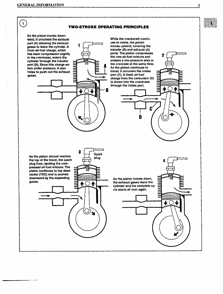
GENERAL INFORMATION 3 0 TWO-STROKE OPERATING PRINCIPLES I AS the piston travels down- I ward, it uncovers the exhaust port (A) allowing the exhaust gases to leave the cylinder. A fresh air-fuel charge, which has been compressed slightly in the crankcase, enters the cylinder throughsthe transfer port (B). Since this charge en- ters under pressure, it also helps to push out the exhaust gases. As the piston almost reaches the top of the travel, the spark plug fires, igniting the com- pressed air-fuel mixture. The piston continues to top dead center (TDC) and is pushed downward by the expanding gases. While the crankshaft contin- ues to rotate, the piston moves upward, covering the transfer (B) and exhaust (A) ports. The piston compresses the new air-fuel mixture and creates a low-pressure area in the crancase at the same time. As the piston continues to travel, it uncovers the intake port (C). A fresh air-fuel charge from the carburetor (D) As the piston travels down, the exhaust gases leave the = - I cylinder and the complete cy- = - - cle starts all over again. www.manuals-n-more.com.au GENERAL INFORMATION TWO·STROKE OPERATING PRINCIPLES As the piston travels down- ward, it uncovers the exhaust port (A) allowing the exhaust gases to leave the cylinder. A fresh air-fuel charge, which has been compressed slightly In the crankcase, enters the cylinder through the transfer port (8). Since this charge en- ters under pressure, It also helps to push out the exhaust gases. As the piston almost reaches the top of the travel, the spark plug fires, igniting the com- pressed air-fuel mixture. The piston continues to top dead center (TDC) and Is pushed downward by the expanding gases. 1 3 B While the crankshaft contin- ues to rotate, the piston moves upward, covering the transfer (8) and exhaust (A) ports. The piston compresses the new air-fuel mixture and creates a low-pressure area in the crancase at the same time. As the piston continues to travel, It uncovers the intake port (e). A fresh air-fuel charge from the carburetor (D) is drawn Into the crankcase through the Intake port. As the piston travels down, the exhaust gases leave the cylinder and the complete cy- cle starts all over again. 3
Upon purchasing this manual, you will receive a .PDF file containing an email contact. After contacting us, you will receive a reply with a link to access the manual for your 1998 EVINRUDE JOHNSON 50HP 2-STROKE OUTBOARD.
This comprehensive manual covers every aspect of your machine, providing detailed guidance on every nut and bolt. With hundreds of pages, it offers solutions for various issues, from simple tasks like an oil change to more complex procedures like a transmission swap. The manual includes numerous illustrations to assist you and features easy-to-understand text throughout.
Utilize the search function to navigate the manual efficiently and print the necessary pages as needed. This Factory Service Repair Manual is designed to walk you through the fundamentals of maintenance and repair, providing step-by-step instructions to empower you with the knowledge that factory-trained technicians possess. By leveraging the insights in this service repair manual, any owner can confidently make informed decisions regarding the maintenance and repair of their machine.
Rest assured, in addition to the high-quality service manual, we are committed to delivering excellent customer service, ensuring your satisfaction with your purchase.
Recently Viewed
5,521,897Happy Clients
2,594,462eManuals
1,120,453Trusted Sellers
15Years in Business
Price:
Actual Price:
1998 EVINRUDE JOHNSON 50HP 2-STROKE OUTBOARD Factory Service & Work Shop Manual